AMAZON multi-meters discounts AMAZON oscilloscope discounts
By themselves, the circuits described so far are of relatively little practical value because all of the components discussed in the previous sections have been passive devices. They can reduce (or attenuate) a signal, but they cannot increase (or amplify) it.
For practical electronic circuits you also need active devices. Active devices are components that can amplify or in some other way actively alter a signal. The first practical active device, and probably the simplest, is the triode vacuum tube. But before you can examine how this device works, you need to look at a couple of related passive devices.
Light bulbs
The vacuum tube is closely related to the common light bulb. In fact, a light bulb could be called a single element vacuum tube.
FIG. 1 shows the construction of a typical light bulb. A thin, specially pre pared wire is enclosed in a glass bulb and all of the air is pumped out, creating a vacuum within the bulb. Electrical connections to the wire (called the filament) can be made from outside the bulb via a metal base.
When an electric current passes through the filament, its resistance causes it to heat up. The special type of wire used for the filament will glow when heated, producing light. Some of the filament material is inevitably destroyed by this process, which is why light bulbs eventually burn out. If you look inside a burned-out light bulb, you’ll see that the filament wire is broken.
The resistance of the filament determines the wattage consumed by the bulb (and thus the brightness of the emitted light). For example, if the filament is 144 U and works off of standard house current (nominally 120 V), the current drawn by the bulb will be equal to the voltage divided by the resistance. (Ohm’s law—I = E/ R). In this example, I = 120/144, or about 0.83 A. This means the power consumed by this particular light bulb (P = EI) is approximately 100 W
-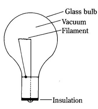
--1 Construction of a typical light bulb.
It takes more energy to heat up the filament to the glowing point, than to maintain its temperature once it 4s heated. In other words, the resistance of the filament is higher when it’s cold. This means when power is first applied to a light bulb, the current drawn will flow in a large surge before settling down to its nominal value. This surge current can be several times larger than the nominal current flow. For this reason, no power is saved by turning out a light if it will be turned back on within a few minutes.
The diode
In addition to emitting light, the heated filament in a light bulb also emits a stream of electrons. If a second element is placed within the vacuum-tube envelope, and given a positive charge, it will attract these electrons. That is, a current can be made to flow between the elements within the bulb, or tube. Because this type of tube has two elements, it’s called a diode. Actually, most practical diodes have three elements, as shown in FIG. 2.
The positively charged element is called the plate, or anode. The stream of electrons is emitted from the cathode, which is given a negative charge by the external circuit. The filament, or heater is generally not considered an active element in the tube. It simply heats up the cathode so it can emit electrons easily. Heating the cathode directly would result in less efficient operation and a tube with a shorter life expectancy.
Usually the heater circuit is electrically isolated from the main circuit. In most tube equipment, there is a separate power source (or transformer winding) just for powering the filaments of the tubes. For the longest possible life, the filaments should be heated with an ac voltage, rather than dc.
The most common schematic symbols for diodes are shown in FIG. 3. Some times the filament is not shown in the schematic diagram at all, as in FIG. 3B and 17-3C. The symbol in FIG. 3C isn’t often used for vacuum tube diodes (see the next section), but it occasionally shows up in certain schematics.
-Filament
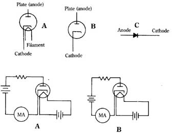 (top)- --3 Schematic symbols for
diodes. (above) -- --4 Test circuit for a diode. Forward bias (A); reverse
bias (B).
(top)- --3 Schematic symbols for
diodes. (above) -- --4 Test circuit for a diode. Forward bias (A); reverse
bias (B).
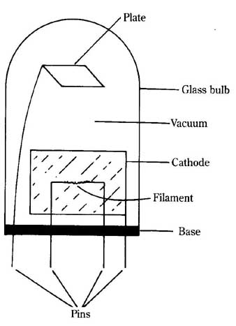
--2 Construction of a typical tube diode.
FIG. 4 shows a simple circuit for testing the action of a diode. When the power source is connected as shown in FIG. 4A, a current flows through the am meter. The value of this current will be determined primarily by the resistor. The diode electrically looks like a very small resistance—almost a short circuit. The diode is forward biased.
However, if the polarity of the dc voltage source is reversed, as in FIG. 4B, no current will flow (or very, very little), because the plate cannot emit electrons. The diode is now reverse biased, and its resistance is extremely high.
The basic principle of a diode is that current can flow through it in one direction but not in the other. An ideal diode has zero resistance if measured from cathode to anode but infinite resistance from anode to cathode. Practical diodes have some resistance when forward biased, but the value will be very low. Similarly, some cur rent will flow through a diode when it’s reverse biased, but the resistance will be so high the current will be of a negligible value.
Considering the way a diode behaves in a dc circuit, what would happen if it were placed in an ac signal path? In an ac circuit, only that portion of the applied signal with the correct polarity can pass through the tube, and the rest of the signal will be blocked. FIG. 5 shows the effect of a basic diode circuit on a simple sine wave.
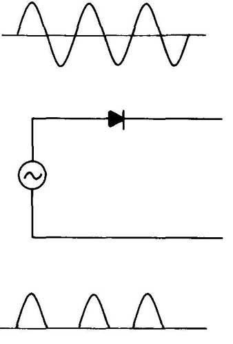
--5 Effect of a diode on a sine wave.
If you add a capacitor, as shown in FIG. 6, its charging and discharging times will tend to smooth out the waveform, producing a more or less dc voltage from an ac source. See the section on power supplies for additional information.
Triodes
As useful as a diode is, it still can’t amplify. To amplify, you need to add a third active element to our tube (ignoring the heater). This new element is called the grid (sometimes the control grid), and such a three element tube is called a triode.
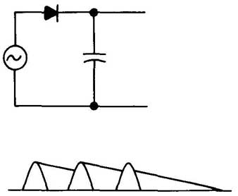
--6 Effect of a diode and a filter capacitor on a sine wave.
FIG. 7 shows the construction of a typical triode, and FIG. 8 shows the most common schematic symbols for the device. As with the diode, the heater is sometimes omitted from the schematic diagram, because it’s not a part of the actual circuit. The heater connections are always assumed.

(L) --7 Construction of a typical triode. (R) --8 Schematic symbols for a
triode.
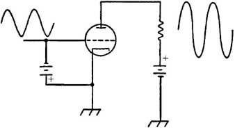
FIG. 9 shows a simple demonstration circuit for a triode tube. For simplicity and convenience, the heater circuit is not shown in the diagram—the heater circuit is identical to the one in the diode circuit discussed previously. As a matter of fact, all tube circuits use the heaters in essentially the same way—this is why they can be omitted from the diagrams. When you see a tube in a circuit, you automatically know you need to apply a voltage across the heater. The level of this volt age varies from type to type, and will be specified by the manufacturer.
The grid in a triode tube is a metallic mesh. That is, it has holes in it that allow electrons from the cathode to pass through it on their way to the plate. Just how many electrons can pass through the grid (that is, the current) depends on its electrical charge. If the grid is made very negative with respect to the cathode, it will repel all of the electrons (which are also negatively charged), and let none of them pass through to the plate. The voltage at which all current through the tube is blocked is called the cutoff point of the tube.
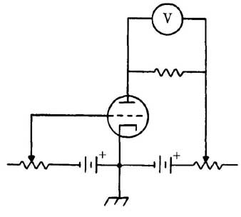
--9 Demonstration circuit for a triode.
As the voltage on the grid is made more positive (or less negative) with respect to the cathode, more and more electrons can pass through the mesh and get to the plate. At some point, all of the electrons emitted by the cathode will reach the plate. This point is called the saturation point of the tube.
If the grid is made even more positive past the saturation point, it will start to attract the electrons itself, once again preventing them from reaching the plate. Usually the grid is slightly negative with respect to the cathode in practical circuits.
Using a hypothetical tube, examine some of the effects that take place in this kind of circuit. For this example, use the cathode as your reference point. That is, the cathode is grounded, which means its voltage is, by definition 0 V.
Assume the grid voltage (Eg) is 0 V. If the plate voltage (Er) is also 0, obviously no current will flow through the tube. If you increase the plate voltage to 25 V, about 1.8 mA (0.0018 A) of current will flow through the plate circuit. If the load resistor (R3 is 5000 , the voltage drop across it will be 0.0018 X 5000, or 9 V. The rest of the plate voltage is used up (dropped) by the tube itself.
Increasing the plate voltage further, to 50 V, will cause a 4 mA (0.004 A) current to flow. The voltage drop across RL is now equal to 0.004 X 5000, or 20 V, and 30 V is dropped by the tube itself.
Increasing the plate voltage to 75 V increases the current flow to 7.25 mA (0.00725 A). The voltage drop across the load resistor is now equal to 0.00725 X 5000, or 36.25 V.
Finally, increasing E to 100 V will increase the current flow to 11 mA (0.011 A). RL drops 0.0 11 X 5000, or 55 V under these conditions.
100 V in the plate circuit is the saturation point of this particular tube with a 0 V grid voltage. The current drawn through the tube cannot be increased further without risking damage to the tube.
FIG. 10 shows a graph of this plate voltage to current ratio. Notice that it’s not a straight line, but a curve. Figures -11 and -12 show similar graphs for the same tube, but with the grid voltage at —2 V and —4 V, respectively. These graphs are collectively called a family of plate characteristic curves for this specific tube. Other tubes will have somewhat different curves, but they will always exhibit basically the same shape.
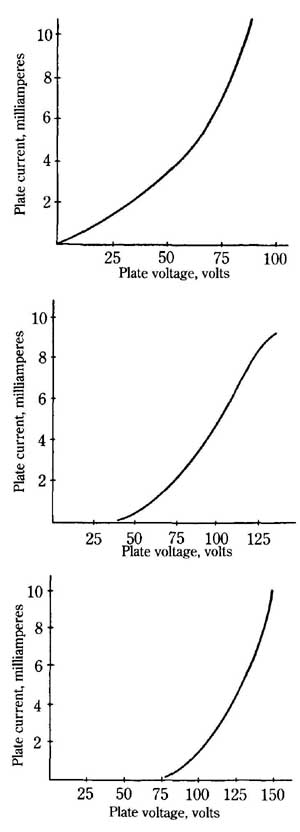
--10 Characteristic plate current curve for a typical = 0 V.
-- --11 Characteristic plate current curve for a typical = —2 V.
--- 12 Characteristic plate current curve for a typical = —4V.
Obviously you could eliminate the tube altogether and just vary the resistance through RL directly. In actual practice, the plate voltage is usually held at a constant level, and the grid voltage (Eg) is varied.
Assume a plate voltage of 100 V. You already know that if E equals 0 and E equals 100, then the current will be 11 mA, and the voltage drop across the 5000 ohm load resistor will be 55 V.
If the grid voltage is changed to —1 V (remember, the grid should be negative with respect to the cathode), the current through the plate circuit will be 8 mA (0.008 A). The negative charge on the grid is repelling some of the electrons from the cathode. The voltage drop across the load resistor will be equal to 0.008 X 5000 or 40 V.
At a grid voltage of —2 V only 5 mA (0.005 A) will flow through the plate circuit. The load resistor will drop 0.005 X 5000 or 25 V.
The entire graph for a constant E of 100 V, and a variable Eg is shown in FIG. 13. Notice that when Eg is —6 V or less, no current will flow through the plate circuit at all. This point is the cutoff point. Compare the graph in FIG. 13 to the one in FIG. 12. Notice that although it takes a 100 V range in the plate voltage to produce an 11 mA range of plate current, it takes only a 6 V range of grid voltage to produce the same plate current range. A relatively small change in grid voltage produces a relatively large change in the plate current, and this produces a fairly large voltage drop change across the load resistor.
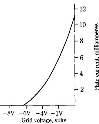
--13 Characteristic grid voltage curve for a typical tube—Er = boy.
If an ac signal is applied to the grid, the signal across the load resistor will be a larger replica of the input signal. This process is called amplification (see FIG. 14).
--14 Amplification.
Of course, the energy across the load has to be provided by the plate voltage source— you can’t get something for nothing. The voltage drop of the load resistor will always be less than the voltage applied to the plate circuit.
The amount of amplification in any given circuit is called the gain. How much gain a specific tube is capable of is called the amplification factor, which is usually represented by the Greek letter p.. (mu). The amplification factor is determined by the ratio of the change in grid voltage needed to produce a given change of current and the change in plate voltage required for the same amount of current change. That is:
μ = Δ E_P/Δ E _g(Equation 1)
where μ (Greek mu) is the amplification factor Δ E_p is the change in plate voltage (symbol is Δ, and is used to represent a changing value). E_g is the change in grid voltage. In the sample tube, increasing the plate voltage 20 V will increase the output current about 2.5 mA, and a change of about 1 V in the grid will produce the same change in current. Therefore, p. equals 20/1, or an amplification factor of 20. As in the diode, current can flow through a triode in only one direction—from cathode (—) to plate (+). Reversing the polarity of the plate voltage will automatically result in zero cur rent flow, regardless of the value of either E or Eg which is true of all tubes.
Tetrodes
A major problem with triodes is due to interelectrode capacitance. That is, the electrodes within the tube act like the plates of a capacitor. See FIG. 15.
The capacitance between the plate and the grid is particularly significant, be cause it can allow ac current from the plate circuit to leak back into the grid circuit, putting a severe limitation on how much gain the tube can put out. This effect can be greatly reduced by adding a second meshed element called a screen grid, which is placed between the original control grid and the plate. FIG. 16 shows the schematic symbol for this type of four element tube, which is called a tetrode.
The screen grid is connected so that it’s positive with respect to the cathode, but somewhat negative with respect to the plate. A capacitor is usually connected from the screen grid to the cathode. This will have no effect on the dc voltage levels, but any ac signal that manages to get into the screen grid circuit will be shorted to the cathode, which is generally at ground potential (0 V). The diagram for the basic tetrode circuit is shown in FIG. 17.
Because the screen grid is physically closer to the cathode than the plate is, its positive charge has a greater effect on pulling the electrons through the holes in the control grid than does the plate. This means the plate voltage has very little effect on the current flow through the tube. A very large change in plate voltage would be needed to equal a very small change in the control grid voltage. Of course, this means the amplification factor of such a tube is quite high. A typical triode might have an amplification factor of 20 to 25, but a tetrode amplification figure is often more than 600.
Of course, changing the voltage on the screen grid could alter the current flow through the tube, but in practical tetrode circuits the screen grid is virtually always held at a constant voltage. The current flow through a tetrode is determined almost exclusively by the voltage on the control grid.
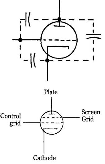 --15 Interelectrode capacitances in a triode.
--- 16 Schematic symbol for a tetrode.
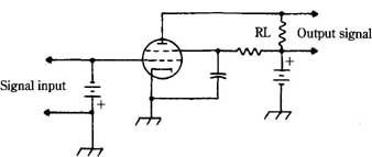
FIG. 17 Basic tetrode circuit.
Because the screen grid is an open mesh, most of the electrons pass right through the large holes in it and go on to strike the even more positively charged plate. A few electrons do strike the screen grid, however, causing a small current to flow through the screen grid circuit.
Passing through the positively charged screen grid tends to speed up the electrons in their path, causing them to strike the plate with considerable force. If this force is large enough, many of the electrons can ricochet off the plate and return to the screen grid. Obviously this is undesirable, because it represents a loss of current flow through the plate circuit. This problem is called secondary emission.
Pentodes
The problem of secondary emission can be greatly reduced by the addition of yet another grid element. This one is called a suppressor grid. The suppressor grid is placed between the screen grid and the plate, and it’s usually connected directly to the cathode, so it’s quite negative with respect to the plate.
The main electron stream is speeded up by the screen grid. The electrons pass through the holes in the suppressor grid so fast the negative charge doesn’t have a chance to repel them, but it does slow them down a bit. Any secondary electrons that bounce off of the plate are repelled by the suppressor grid negative charge, so they are forced to return to the positively charged plate.
The plate voltage in a pentode (five-element tube) can vary over an extremely large range without appreciably changing the current in the plate circuit. As a matter of fact, the plate voltage can even drop slightly below the screen grid voltage without a serious drop in the output current.
The schematic symbol for a pentode is shown in FIG. 18. As with all other tubes, the heater circuit is often omitted from schematic diagrams.
FIG. -18 Schematic symbol for a pentode: Grid; Plate; Suppressor grid ; Control grid; Screen
In most pentodes, the suppressor grid is brought out to its own terminal pin and is connected to the cathode via the external circuit. In some pentodes, however, the suppressor grid is internally connected to the cathode. This type of tube is usually shown schematically as in FIG. 19.
The amplification factor of a pentode can be extremely high. Some tubes have an amplification factor of 1500 or higher. Compare this value to the amplification factor of a simple triode!
Of course, because pentodes have more elements, and are more complicated to manufacture, they are more expensive. Triodes and tetrodes are usually used whenever possible to achieve the desired results.
Multiunit tubes
Some tubes actually contain more than one set of electrodes in a single bulb. In other words, more than one tube is contained in a single glass envelope. The most common combinations are dual diodes, dual triodes, and diode-triode combinations. Tetrodes and pentodes are rarely found in multiunit tubes.
Some dual tubes have a common cathode, and many share a common heater filament. This means the element is used in both tubes.
FIG. 20 shows the schematic symbol for a dual triode. In many circuits the two sections of the tube can be used in entirely different circuits.
Cathode-ray tubes
There are a number of special tube types available for specific, unique applications. One that merits special discussion here is the cathode-ray tube, or CRT The key principle in a cathode-ray tube is that certain special materials, called phosphors, will glow when struck by an electron beam.
The basic structure of a cathode-ray tube is shown in FIG. 21. The elements that make up the section called the electron gun are shown in more detail in FIG. 22.
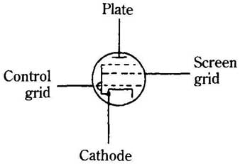
FIG. - 19 Schematic symbol for a pentode with an internally connected
suppressor grid.
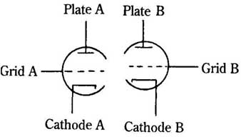
FIG. -20 Schematic symbol for a dual triode.
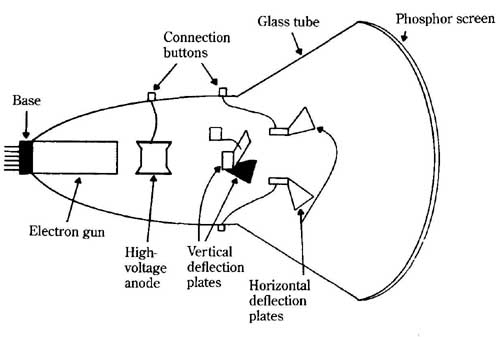
FIG. - 21 Basic structure of a CRT (cathode ray tube).
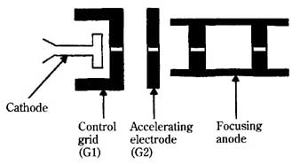
FIG. -22 Basic structure of an electron gun from a CRT.
The cathode is indirectly heated (there is a separate heater filament) and emits a stream of electrons, as in any tube. There is one difference, however. In ordinary tubes, the cathode generally emits electrons from its sides, but the cathode in a CRT is designed so that it emits electrons primarily from the end facing the phosphor screen.
The cathode is enclosed in a metal cylinder that acts as the control grid. There is a minute opening at the end of this grid, facing the screen. This hole is for the electrons to pass through. Because it’s so small, it forces the electrons to travel in a narrow beam.
By making the control grid negative with respect to the cathode, some of the electrons are repelled, and thus, aren’t allowed to pass through the opening, If the control grid is made negative enough, it will cut off the electron beam to the rest of the tube entirely.
In other words, changing the voltage to the control grid with respect to the cathode controls (or modulates) the intensity of the electron beam. Holding the volt age on the control grid constant and varying the cathode voltage would have exactly the same effect. The intensity of the electron beam is determined by the difference between these two voltages. Both methods are commonly used in practical circuits.
The more intense the beam (that is, the greater the number of electrons) striking the phosphors, the brighter they will glow. So, modulating the cathode-control grid voltages will control the amount of light emitted.
Once the electron beam has passed through the control grid, it moves through a second grid element, called the accelerating electrode, or grid 2. This electrode is a metal cylinder or disk with a small opening for the electron stream to pass through.
A high positive voltage is applied to the accelerating electrode. This voltage is held constant—that is, it’s not modulated.
As the name implies, the purpose of this element is to accelerate, or speed up, the electrons as they pass through. In this respect, it’s somewhat similar to the screen grid in a regular tetrode.
Because the accelerating electrode is highly positive it drains off some of the electrons from the passing stream. But the electrons are moving too fast for the positive voltage to deflect them from the narrow beam created by the narrow opening in the end of the control grid.
Next, the electron beam passes through the focusing anode. Again, the name suggests the function—this element focuses, or tightens the stream of electrons into a still finer beam.
The focusing anode is a metal cylinder that is open at both ends. Inside the cylinder are two metal plates with tiny holes in the center. The element acts similarly to a glass focusing lens in an optical system.
In addition to focusing the electron beam, this electrode also speeds it up still further. A rather large, constant positive voltage is applied to the focusing anode.
These four elements (the cathode, the control grid, the accelerating electrode, and the focusing anode) comprise the electron gun. The electron gun is so named because it “shoots” a narrow beam of electrons at the phosphor screen. Electrical connections to these electrodes are brought out through metal pins in the base of the tube, just as with ordinary tubes. Once the electron beam leaves the electron gun, it passes through a second anode. Because an extremely high (several thou sand volts) positive potential is applied to this element, it’s called the high voltage anode. The electrical connection for this element is brought out to a metallic button on the body of the tube.
Within the electron gun, the accelerating electrode and focusing anode (some times called anode #1) are both held at a positive voltage, and might tend to attract a large number of electrons out of the beam if the higher positive voltage of the high voltage anode (anode #2) didn’t have such a strong attraction that it pulls the electrons on through. Despite this high attraction, even the high voltage anode doesn’t drain many electrons out of the beam. Because the electron beam is very tightly focused, and moving at an extremely high speed, and because the high voltage anode is an open cylinder, almost all of the electrons pass through it to strike the phosphor screen.
If the tube consisted only of the elements described so far, the electron beam would always strike the exact center of the screen. Obviously, this wouldn’t be particularly useful. You need a way to deflect the beam so that it can strike any portion of the screen you choose. There are two basic ways of accomplishing this—electro static deflection and electromagnetic deflection.
The cathode-ray tube shown in FIG. 2 1 is of the electrostatic deflection type. In this kind of tube there are four deflection plates, with electrical connections made to metal knobs on the outside of the glass envelope.
The plates at the top and bottom of the tube are called the vertical deflection plates. The other set, at the sides, are called the horizontal deflection plates. The electron beam passes between all four plates. For simplicity, ignore the horizontal deflection plates (the ones on the sides) for the time being. If both vertical deflection plates have the same voltage applied to them, they will have no effect on the path of the electron beam, and it will strike the center of the screen. See FIG. 23.
Now, if the lower plate is made more negative than the upper plate, the lower plate will repel the stream of electrons, and the upper plate will attract it. This means the electron beam will move at an upward angle. It will strike the screen near the top—see FIG. 24.
The exact location of the lighted spot on the screen will depend on the voltage difference between the deflection plates. The greater the difference between the plate voltages, the further the spot will be displaced from the center of the screen. It’s very important to realize that the displacement is dependent on the difference of voltage on the plates—not necessarily their absolute values. When you say the lower plate is negative, you are speaking of its relation to its partner—not necessarily with respect to ground. For instance, if the lower plate has an applied voltage of —25 V (with respect to ground), and the upper plate is at + 25 V, the voltage difference is 50 V. The exact same effect on the electron beam can be achieved if the lower plate is at + 100 V over ground and the upper plate is at + 150 V.
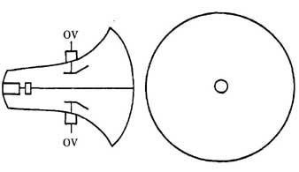
FIG. -23 A CRT with equal voltages applied to the vertical plates.
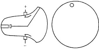
FIG. - 24 A CRT with the lower vertical plate negative with respect to
the upper vertical plate.
Of course, if the relative polarities of the deflection plates are reversed, as in FIG. 25, the effect on the electron beam will also be reversed. A negative upper plate and a positive lower plate will cause the electron beam to move down the screen. The horizontal deflection plates work in the same way, moving the electron beam from side to side. By combining the effects of the horizontal deflection plates and the vertical deflection plates, the electron beam can be aimed so that any desired spot on the phosphor screen can be illuminated.
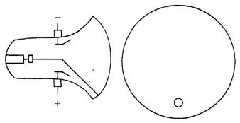
FIG. - 25 A CRT with the lower vertical plate positive with respect to
the upper vertical plate.
The electromagnetic deflection system works basically in a similar manner, but instead of internal deflection plates, electromagnets are placed around the neck of the tube in an assembly called a yoke. See FIG. 26. The yoke is positioned on the neck of the tube so the electromagnets are placed in the places shown in FIG. 27. Notice that these positions correspond directly to the positions of the deflection plates in an electrostatic deflection cathode-ray tube.
Because an electron can be attracted or repelled by a magnetic field (it can be considered as a microscopic magnet itself the relative strength of the electro magnet magnetic fields can control the angle of the electron beam, and thus, the position of the lighted spot on the phosphor screen, Of course, the strength of each magnetic field is dependent on the amount of voltage applied to the appropriate electromagnet.
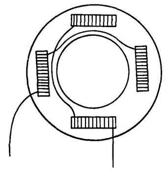
FIG. - -26 Construction of a CRT yoke.
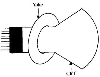
FIG. 27 Placement of the yoke on the neck of the CRT.
These two deflection systems are very similar. Generally, the electromagnetic deflection type CRT is more complex to manufacture, and is, therefore, more expensive, as a rule, than the electrostatic deflection type CRT However, the electromagnetic deflection system allows for more precise control of the electron beam’s angle. This means the image formed on the screen is sharper, or has higher resolution (finer detail).
In oscilloscopes and radar monitors, high resolution isn’t particularly critical, so the less expensive electrostatic deflection type CRTs are usually used. A television picture tube, on the other hand, demands a very high degree of resolution, so an electromagnetic-deflection CRT is usually employed for that application.
If you apply a repeating ac wave shape to the horizontal deflection plates (or electromagnets) the electron beam will move back and forth across the screen in step with the ac frequency. The same voltage is applied to each of a pair of deflection plates (magnets), but one is inverted 180 degrees, so as one voltage increases, the other decreases, so the difference between the two plate voltages will vary in the same manner as the applied signal. See FIG. 28.
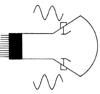
FIG. - 28 Applying a repeating ac wave to the horizontal plates.
Usually the best waveform for moving the lighted dot across the screen is the sawtooth, or ramp wave. This wave shape is shown in FIG. 29. Notice that the voltage starts at some specific minimum value and gradually builds up to a maxi mum level. Then it quickly drops back to the original minimum value, and the entire cycle is repeated.
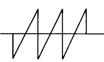
FIG. 29 A ramp wave.
At the minimum voltage point of the cycle, the electron beam is angled to strike the far left edge of the screen (facing the screen from the front of the tube). The left deflection plate is exhibiting maximum attraction, and the right deflection plate is exhibiting maximum deflection. As the voltage increases, the left deflection plate gradually loses some of its attraction, and the right deflection plate loses some of its repulsion. The lighted dot moves across the screen from left to right. When it’s in the center of the screen, both deflection plates are at an equal voltage. From this point on, the right deflection plate starts to attract the electron beam, and the left deflection plate starts to repel it. The lighted dot continues to move across the screen, until, at the maximum applied voltage, it’s at the far right edge of the screen. This part of the cycle is called the sweep. The line drawn by the electron beam across the screen is called the trace.
During the next part of the cycle, the applied voltage drops quickly back to the original minimum level, causing the electron beam to snap back to its original far left position. This process is called the retrace, or flyback.
In most practical circuits, the electron gun is cut off (no electron beam at all) during the flyback time. It’s impossible to produce a sawtooth wave with an instantaneous flyback. It takes a certain finite amount of time to go from the maximum voltage to the minimum voltage, lithe beam were allowed to strike the screen during the retrace time, it could produce a confusing trace image. So the screen is only illuminated by the left to right movement of the electron beam. During the retrace it’s dark.
The frequency of this sawtooth waveform is called the sweep frequency, be cause it determines how rapidly (and how many times per second) the electron beam will sweep across the screen.
If, at the same time the horizontal plates are being fed by the sweep signal, you apply another waveform to the vertical deflection plates, something quite interesting (and useful) takes place. Between any two given instants, the electron beam will be moved a small amount, so each instantaneous value of the vertical deflection voltage will be displayed in a different horizontal position on the screen. In other words, if a sine wave of the same frequency as the sweep signal is applied to the vertical deflection plates, the electron beam will draw the pattern shown in FIG. 30 on the phosphor screen. lithe frequency of the sine wave is doubled, two complete vertical cycles will take place in the time required for a single horizontal cycle, so two complete waveforms will be displayed on the screen, as in FIG. 31.

FIG. - -30 CRT screen—vertical frequency equals horizontal frequency.
FIG. - -31 CRT screen—vertical frequency equals two times the horizontal frequency.
The sweep frequency is selected to be fast enough so that the trace will appear to be a solid, continuous line. Actually, at any given instant, the electron beam is striking only one tiny spot on the screen. The phosphors glow due to a property called fluorescence. Another property of these materials, which is known as phosphorescence allows them to continue glowing for a brief time after the electron beam stops striking the spot. This property, coupled with the persistence of vision (the eye continues to see a light source for a brief moment after it’s removed) gives the illusion of a solid image.
The exact chemical properties of the phosphors used determine the phosphorescence time. Different applications require different amounts of afterglow. A typical oscilloscope generally uses a phosphor that produces a green trace with a moderate afterglow time. If the oscilloscope is intended to display non-cyclic voltage patterns of very short duration, a greater degree of phosphorescence is necessary. For television pictures, on the other hand, a relatively short afterglow time is preferable. In a black and white picture tube, the phosphors glow white. In a color picture tube, three types of phosphors are used together. These phosphors glow red, green and blue. This will be explained in the section on television.
The screen of a cathode-ray tube can either be round (as in most oscilloscopes and radar monitors), or rectangular (as in most television picture tubes). With the round type, the size is specified by the diameter of the screen, and with the rectangular shape, the size is defined by the diagonal. See FIG. 32.
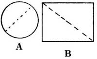
FIG. - -32 Measuring CRT screen sizes.
Because the electron beam strikes the phosphor screen at an extremely high speed, secondary emission could be a problem, producing reflections at undesired portions of the screen. This problem is generally prevented by lining the interior surface of the glass tube with a conductive graphite coating called the Aquadag. This Aquadag is tied electrically to the high-voltage anode. Because it has a high positive potential, any electrons bouncing off of the screen will be attracted to the Aquadag coating, rather than striking the screen a second time.
QUIZ
1. What are the active parts of a diode tube?
A Anode, grid, and cathode
B Anode and plate
C Anode and cathode
D Cathode and grid
E None of the above
2. What is the simplest type of tube capable of amplification?
A Triode
B Anode
C Diode
D Tetrode
E None of the above
3. Under what conditions will a diode conduct?
A At all times
B When it’s forward biased
C When it’s reverse biased
D When it’s amplifying
E None of the above
4. Which of the following best describes the grid in a tube?
A A large flat plate
B A metallic mesh
C A cone-like shape
D A filament
E None of the above
5. What happens if the grid is made more positive than the saturation point?
A Electrons are drawn to the grid and don’t reach the plate
B No further amplification takes place
C The tube elements might be damaged
D The tube stops conducting
E None of the above
6. What is the term specifying the maximum gain a tube is capable of?
A pS-characteristic curve
B f factor
C 13—attenuation factor
D ps—amplification factor
E None of the above
7. What is the purpose of the screen grid?
A To allow greater amplification
B To reduce the effect of interelectrode capacitances
C To reduce impedance of the tube
D To make the tube more durable
E None of the above
8. How many electrodes does a pentode have?
A Two
B Three
C Four
D Five
E Six
9. What is the name of an electrode found in a pentode but not in a tetrode?
A Control grid
B Screen grid
C Suppressor grid
D Signal grid
E None of the above
10. What type of tube is used to display signals on an oscilloscope?
A Tetrode
B Cathode-ray tube
C Filament tube
D Pentode
E None of the above
<< >>