AMAZON multi-meters discounts AMAZON oscilloscope discounts
Semiconductors have an unusual property that has not been taken advantage of until recently. Semiconductor materials are light sensitive. That is, the amount of light striking them affects their electrical characteristics. Ordinarily, this photosensitivity is very undesirable in most applications, because the light level is generally uncontrolled. For this reason, most semiconductor components (transistors, diodes, ICs, etc.) are normally enclosed in a light-tight housing made of plastic or metal. This housing also protects the delicate semiconductor crystal from moisture, and stray particles (dust, etc.).
In certain applications, photosensitivity can be highly desirable, or even essential. An obvious example is a light meter. An electronic circuit cannot measure the light level unless it can “see” it.
A number of special semiconductor photosensitive devices (or light sensors) are now available. Some feature PN junctions (like ordinary diodes and transistors), and others are made from a single, junctionless slab of semiconductor crystal. The specific reaction to detected light depends on the construction of the photosensitive component and the specific semiconductor material used.
A junctionless semiconductor light sensor is generally known as a photo cell. There are two basic types of photocells. They are the photovoltaic cell and the photoresistor.
Photovoltaic cells
A photovoltaic cell is a simple slab of semiconductor crystal, usually primarily made up of silicon. The semiconductor material is spread out onto a relatively large, thin plate for the greatest possible contact area. The more of the semiconductor material that is exposed to light, the stronger the response to the light will be.
In essence, a photovoltaic cell functions something like a dry cell (battery). This face is indicated in the schematic symbol for the device, shown in Fig. __1. Notice that this symbol is similar to the one used to represent an ordinary voltage cell or battery.
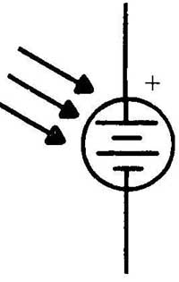
__1 Schematic symbol for a photovoltaic cell.
When the silicon surface is shielded from light, no current will flow through the cell. But when it’s exposed to a bright light a small voltage is generated, due to what is known as the photoelectric effect.
If an illuminated photovoltaic cell is hooked up to a load, a current will flow through the circuit. See Fig. __2. Just how much current will flow is dependent on the amount of light striking the surface of the cell. The brighter the light, the higher the current available.
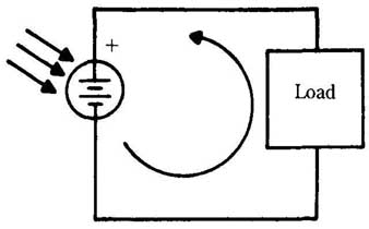
__2 Current flowing through a photovoltaic cell.
The cell output voltage, on the other hand, is relatively independent of the light level. The voltage produced by most photovoltaic cells is in the range of about 0.5 V. The most obvious use for a photovoltaic cell is as a substitute for an ordinary dry cell. Of course, the 0.5 V output of a single cell is too low for most applications, so a number of photovoltaic cells can be added in series to form a battery, just as with ordinary dry cells. If the circuit you want to power from photovoltaic cells requires more power than your photocells can provide, more cells can be added as in a parallel battery.
You can power almost any dc circuit with a combination of series, parallel, or series-parallel connected photocells. This type of grouping of photocells is often called a solar battery, but it will work just as well under artificial light.
There’s one factor that you should keep in mind: the more cells there are in a solar battery, the larger the total surface area will be, and the harder it will be to arrange the cells so they will all be lighted evenly. This means that usually solar batteries are best suited for fairly low power circuits.
A related use for photovoltaic cells is in a recharger for nickel-cadmium batteries. Figure __3 shows a typical arrangement. The diode can be almost any standard type, such as a 1N914. The diode is needed to protect the photocells. If the diode wasn’t included in the circuit, and the cells were inadvertently darkened, the nickel- cadmium battery could start to discharge through them. This reverse polarity could quickly ruin the photocells.
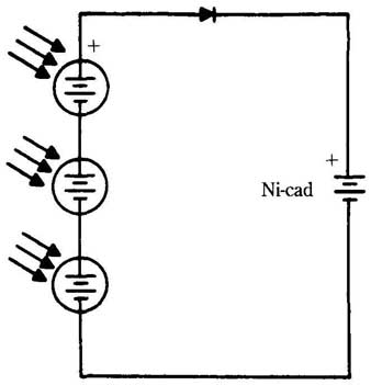
__3 A photovoltaic cell nickel-cadmium battery recharger.
Bear in mind that photovoltaic cells, like any other dc voltage source have definite polarity. That is, one lead is always positive and the other is always negative. Never reverse the polarity
Another frequent application for photovoltaic cells is in light-metering circuits.
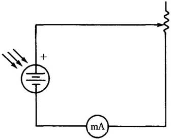
A very simple light meter is shown in Fig. __4. Because the current flowing through a photocell is proportional to the amount of light striking its surface, measuring the current with a milliammeter will give a direct indication of the degree of illumination. The meter scale can be calibrated in whatever units are convenient.
The measurements made with this type of simple circuit won’t be very precise, but the circuit is perfectly functional for comparative measurements.
The potentiometer adjusts the sensitivity of the meter. Generally this should be a trimpot that is set once for calibration, then left alone for the measurements. For best results the meter should be as sensitive a unit as possible, but care should be taken that the meter is not so sensitive that a strong light source can slam the pointer off the scale.
__4 A photovoltaic light meter.
A photovoltaic cell can be used to trigger a relay. The basic setup for this is shown in Fig. __5. Notice that the controlled circuit requires a separate power sup ply. The voltage generated by the photocell only opens or closes the relay contacts.
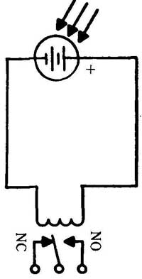
__5 A light-operated relay.
Because the output of the photocell is fairly small, it can only drive a relatively light duty relay. If the circuit you want to control requires a heavier relay, there are two ways to solve the problem. One method is to use the light-duty relay to control the heavy duty unit as shown in Fig. __6. Alternatively, the output of the photocell can be amplified with a transistor, as shown in Fig. __7.
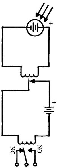
__6 Using a light-duty relay to drive a heavy-duty relay.
The potentiometer is again used to adjust sensitivity Notice that both of these methods require an extra voltage source in addition to the photocell and the con trolled circuit power supply.
All of these relay circuits respond only to the presence or absence of light. They are not adjustable to trigger on a specific amount of lighting, because a photocell output voltage is essentially constant.
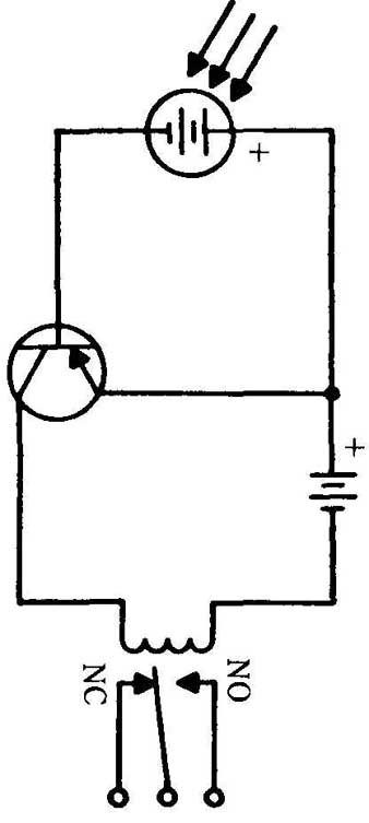
__7 Using a photovoltaic cell to drive a heavy-duty relay with the
aid of a transistor amplifier.
-Photoresistors-
Mother popular light-sensitive device is the photoresistor, or light-dependent resistor. As the name implies, a photoresistor changes its resistance value based on the level of illumination on its surface. Photoresistors generate no voltage themselves. Photo- resistors are usually made of cadmium sulfide, or cadmium selenide.
Functionally, a photoresistor is a light-controlled potentiometer. The light intensity corresponds to the position of the potentiometer shaft. These devices generally cover quite a broad resistance range—often on the order of 10,000 to 1. Maximum resistance—typically about 1 M-ohm (1,000,000 ohm) is achieved when the cell is completely darkened. As the light level increases, the resistance decreases.
Because photo-resistors are junctionless devices, like regular resistors, they have no fixed polarity. In other words, they can be hooked up in either direction without affecting circuit operation in any way. Figure __8 shows the schematic symbol for a photoresistor.
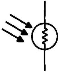
__8 Schematic symbol for a photoresistor.
Photoresistors are perfect for a wide range of electronic control applications. They can easily be used to replace almost any variable resistor in virtually any circuit.
Photoresistors can also be used in many of the same applications as photovoltaic cells, usually with just the addition of a battery and another resistor. They offer the advantage of being sensitive to different light levels. For example, Fig. __9 shows a light-controlled relay circuit. In this circuit, R1 can be adjusted so that the relay switches at any desired light intensity level.
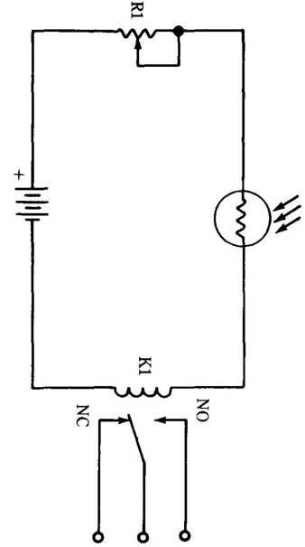
__9 Light-activated relay using a photoresistor.
Figure __10 shows a simple light meter built around a photoresistor. Photoresistors can also be used in many applications where a photovoltaic cell would not be used. Because a photoresistor is a variable resistance, it can be used in place of almost any standard potentiometer in almost any circuit. If appropriate for the application at hand, a photoresistor can be substituted for a fixed resistor.
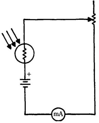
__10 A photoresistor light meter.
-Other photosensitive components-
Any standard semiconductor device (with one or more PN junctions) can be made photosensitive, simply by placing a transparent lens in the component’s housing so the semiconductor material is exposed to light. A great variety of light-sensitive components are now available. Most of these are light controlled versions of more familiar semiconductor devices.
Figure __11 shows the schematic symbol for a photodiode. A phototransistor is shown in Fig. __12. Figure __13 shows a light-activated SCR (silicon-controlled rectifier). This last component is commonly known by its acronym, LASCR.
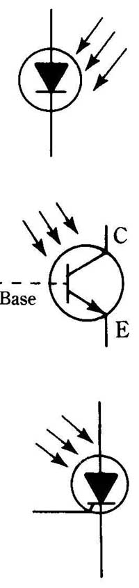
(above: top to bottom): __11 Schematic symbol for a photodiode. __12 Schematic
symbol for a phototransistor. __13 Schematic symbol for a LASCR.
Phototransistors are especially useful in a large number of applications because they can be used as amplifiers whose effective gain is controlled by light intensity.
Usually (though not always) the base lead is left unconnected in the circuit, the base-collector current being internally generated by the photoelectric effect. Many phototransistors don’t even have an external base lead. Many circuits that use standard bipolar transistors could be adapted and rebuilt with phototransistors. This could result in some very unique effects. Of course, the base lead could be used too, so the output would depend on both the signal on the base lead, and the light intensity.
An optoisolator is another extremely useful device. As the name implies, it isolates two interconnected circuits so that their only connection is optical.
In an earlier section, you read about a rudimentary optoisolator can be made from two LEDs. Most practical optoisolators, however, consist of a LED and a photo-cell, or phototransistor encapsulated in a single, light-tight package. The schematic symbols are shown in Fig. __14.
The LED is wired into the controlling circuit, and the photocell is wired into the circuit to be controlled. This provides a convenient means of control with virtually no undesirable crosstalk between the two circuits. Essentially the same effects can be achieved with a separate LED and photoresistor (or phototransistor), but they must be carefully shielded from all external light to prevent uncontrolled interference.
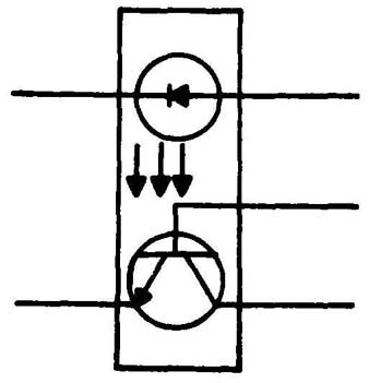
__14 An optoisolator.
--QUIZ--
1. What is the name for a component that changes its resistance in response to light intensity?
A Photovoltaic cell
B Photoresistor
C Potentiometer
D Photo-potentiometer
2. What is the nominal voltage of a photovoltaic cell?
A 0.5V
B 1.0V
C 1.5V
D Varies in proportion to the size of the cell
E None of the above
3. What is the name for the property used in light sensitive devices?
A Piezoelectric effect
B Solar Energy
C LASCR
D Photoelectric effect
E Photo-resistance
4. Which of the following is not a light-sensitive transducer?
A Photodiode
B LASCR
C Photoresistor
D SCR
E None of the above
5. Which type of material is most likely to be photosensitive?
A Conductors
B Semiconductors
C Insulators
6. Which lead is often omitted in a phototransistor?
A Collector
B Emitter
C Base
D Gate
E None of the above
7. Why are ordinary transistors not sensitive to light?
A Different materials are used in their construction
B They only have two PN junctions
C They are enclosed in light-tight housings
D Different biasing is used
E None of the above
8. How many PN junctions does a photoresistor have?
A One
B Two
C Three
D None
E More than three
9. What semiconductor material is most often used in photovoltaic cells?
A Silicon
B Cadmium-sulfide
C Gallium-arsenic
D Cadmium-selenide
E None of the above
10. Which of the following performs a similar function to that of a photovoltaic cell?
A Capacitor
B dc battery
C Inductor
D LASCR
E None of the above
<< >>