AMAZON multi-meters discounts AMAZON oscilloscope discounts
An important part of any electronics technician’s battery of skills is the ability to locate and correct any problems that might show up in a circuit. A newly designed prototype circuit might not function as the designer intended. The technician must determine what went wrong and correct the error in a new prototype. An experimenter might build a presumably debugged circuit from a magazine, but it doesn’t work. Now the experimenter will need to determine if the error is in the published schematic or if there is an error in construction. In either case, the problem must be found and corrected, or the previous efforts will have been wasted. A piece of electronic equipment that once worked properly might start malfunctioning. A technician must locate and repair the portion of the circuit that has become defective.
The process of locating the problem in a malfunctioning electronic circuit is known as Troubleshooting. Repairing the defect is known as servicing. Troubleshooting a complex piece of equipment might seem like a hopeless task at first. But a little common sense can reduce the job to manageable levels. A color television set , for example, might have several hundred discrete components. Do you check each one to make sure that it’s within the manufacturer’s specifications? Presumably it would be possible to locate most defects that way, but it would be extremely inefficient. It could take hours, or even days to find the bad component.
Most complex electronic devices are made up of many less complex stages. By analyzing the functions of these stages, you can narrow down the potential cause of the defect. For example, assume the picture on a color TV is breaking up into broad diagonal stripes, notice that objects are being displayed, although they are distorted and broken up because of the striping. Colors appear normal. The sound is fine. Where is the problem? As a first step, you look at the block diagram for the set. A typical color TV block diagram is shown in Fig. __1. Consider each stage and see if it’s the problem.
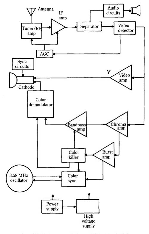
__1 A good block diagram can help a technician pinpoint faulty stages
in a defective circuit. Power supply; High voltage supply
Because the set is operating, you can assume the power supply circuits are working. They might be putting out incorrect voltages, but in this particular case, that doesn’t seem a likely cause of the problem at hand. If you are unsure, it would only take a few moments to measure the supply voltages. If they are reasonably close to their specified values, you can move on. Some technicians always measure supply voltages for all problems. Too high and too low voltages can result in some very odd problems. In this example, you will assume the supply voltages are correct.
You are getting a raster (the CRT is lighting up) so you can eliminate the high- voltage supply and the CRT as suspects. A signal is getting through, so the tuner, RF amplifiers, IF amplifiers, AGC, and separator circuits are probably okay. You have correct sound, so the audio circuits and speaker are not involved. You do have a picture, but it’s broken up. This symptom indicates that there isn’t a problem in the video detector or video amplifier.
Because the color seems to be all right, the defect is probably not in any of the color circuits (chroma amplifier, bandpass amplifier, burst amplifier, color killer, color sync, and the 3.58 MHz oscillator). What does that leave? There is only one section of the block diagram you haven’t at least tentatively ruled out. An experienced technician would probably immediately suspect the sync circuits. The problem you have described is a loss of horizontal synchronization.
In some tough cases, the circuit you suspect might check out fine. There could be a problem in another portion of the circuitry that is causing a surprising symptom. For instance, the sync pulses might be distorted or attenuated in some manner in the video amplifier stage. This problem isn’t as likely, but it could happen.
If a set has multiple symptoms, try to isolate the single stage that could be responsible for all or most of the symptoms. There might be defects in more than one stage, but the odds are that there is a common problem, or one component has faded, causing an overload to damage another component.
Consider another problem. The screen is completely dark, and there is no sound at all. The set just sits there and does absolutely nothing. The average person might consider this a more serious problem. After all, the set isn’t working at all. But an experienced technician will be unconcerned. It will probably be a relatively easy repair.
What could cause the symptoms described? There could be several combinations of multiple causes. For example, the CRT and one of the audio circuits could be defective. But it’s more likely that all of the symptoms are resulting from a problem in a single stage. What stage could account for all of the symptoms (dark screen and no sound)? There is one stage common to everything in the set—the power supply. The other stages probably aren’t getting any power. The culprit could be a blown fuse, a burned-out rectifier diode, a shorted filter capacitor, a broken wire, or any of many other possibilities. (Assume the set is plugged in, of course. It saves time to always check out the simple and the obvious first. Dumb mis takes do happen.)
In this section, you can briefly consider some of the more common types of defects. But first, examine some of the important weapons in the technician’s Troubleshooting arsenal.
Test equipment
To determine the source of a problem in an electronic circuit, the technician uses one or more pieces of test equipment. There is no single all-purpose tester that can solve all problems. Each piece of test equipment is designed for specific purposes.
The most basic pieces of test equipment are the technician’s eyes, ears, and brain. This comment is not meant to be facetious. The technician observes the symptoms with eyes and ears and analyzes them with his brain. The brain tells the technician what stage or stages are likely culprits.
The technician’s eyes can be used to locate many defects. Does a component look burned? Is a wire broken? The technician’s nose can also be helpful. Does something smell burned? The technician can also use the tip of the finger to deter mine if a component is running hot. Of course, the technician’s brain must also analyze the data obtained from the various tests performed. What could cause any unusual values found in the circuit? Generally, when speaking of test equipment, however, you are referring to external electronic circuits designed to measure various electrical characteristics and display their results in some manner.
The VOM
The most basic and versatile piece of equipment available to the electronics technician is the VOM, or volt-ohm-milliammeter. This device is discussed in section 10. A VOM measures dc and ac voltages, dc resistance, and dc current. A few VOMs also measure AC current.
Closely related to the VOM is the VTVM, or vacuum-tube voltmeter. Most VTVMs measure only voltage and resistance, .but not current. One advantage of the VTVM over the VOM is in measuring high-frequency ac voltages. A VOM reading is not usually reliable for frequencies above a few hundred hertz. A VTVM has a far wider frequency response. The VTVM can also usually measure a wider range of resistances.
The average VTVM is well protected against overloading the meter movement and burning out component parts from excessive test voltages. The meter in a VOM can be damaged if , for example, 120 V was applied when the meter was set to a 10 V range. In a VTVM the meter itself is isolated from the input by the vacuum-tube amplifier and scaling circuitry.
A VTVM usually runs on 120 Vac, which means it can only be used where an electrical socket is available. Most standard VOMs have a small battery for resistance measurements and require no further power source. VTVMs are also more bulky than most VOMs. In addition, the tube circuitry in the VTVM gives off heat.
Because a VOM is not plugged into the electrical socket along with the equipment being tested, there is better isolation, ensuring greater safety for the technician. The use of a battery also tends to minimize interference problems from stray RF signals and ac hum.
The tubes in a VTWM need a certain amount of time to warm up before correct readings can be obtained. In addition, readings might tend to drift slightly, especially as the tubes age. Drift is not a problem with a VOM, which is basically a passive device. Because the VOM involves simpler circuitry than the VTVM, it also tends to be more reliable.
The main difference between meters is sensitivity or input impedance. The higher the input impedance of the meter, the less it will load down the circuit being tested. This is because the meter is placed in parallel with part of the circuit to measure voltage.
A typical VOM has a sensitivity of approximately 20,000 ohm/V (ohms per volt). Some go as high as 50,000 ohm/V. Cheap VOMs with an input sensitivity of only 1000 fl/V are also available. These can be useful to an electrician, but an electronics technician should steer clear of them—the sensitivity is far too poor for electronics circuitry.
A typical VTVM will have much greater sensitivity than a VOM. Input impedances of 11 M-ohm (11,000,000 ohm) are common for VTVMs.
A cross-breed type meter is the FET VOM. The FET version is just a regular VOM with a FET amplifier input stage. The FET offers the advantage of isolating the meter movement from the input signal, but a power source is required for volt age and current measurements as well as for resistance measurements. Power can be supplied by a small internal battery, so portability is not compromised. The sensitivity of a FET VOM is around 1 M-ohm/V (1,000,000 ohm).
Examine why input sensitivity is so important. Take a look at the simple circuit shown in Fig. __2. Assume that the battery is putting out 9 V, and the three resistors have the following values:
R1 = 22 k-ohm (22,000 -ohm)
R2 = 47 k-ohm (47,000 -ohm)
R3 = 33 k-ohm (33,000 -ohm)
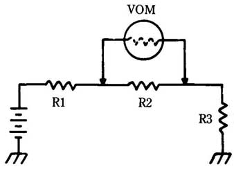
__2 A voltmeter can affect the circuit being tested by acting as a
parallel resistance. VOM, R3
Total circuit resistance is 102,000 ohm. According to Ohm’s law, the current drawn through the circuit works out to:
= 0.0000882 A = 0.0882 mA
The same amount of current flows through each resistor. You can now calculate the nominal voltage drop across resistor R2:
E = IR = 0.0000882 X 47000 4.15 V
Now, assume you hook up a 1000 ohm/V VOM in parallel with R2 to measure the voltage drop. The input resistance of the VOM acts as a parallel resistance with R2, which makes the apparent value of R2 drop to:
= 0.0000213 + 0.01 = 0.0010213 = R 0.0010213
That’s quite a change. The total circuit resistance is now:
R = 22000+ 979 + 33000= 55,979 ohm
This resistance changes the current flowing through the circuit to:
I = 0.00016 A = 0.16 mA
The measured voltage drop across R2 works out to:
E = JR = 0.00016 X 979 0.157 V
That is certainly an unacceptable error when you are expecting a reading of 4.15 V! If the input resistance of the VOM is 20,000 ohm things will look a little better, al though the error will still be significant. First, solving for the effective resistance of the R combination:
= 14000 ohm
Total effective circuit resistance this time is about 69,000 U making the current flow equal to:
= 00 0.00013 A = 0.13 mA
The measured voltage drop across R2 using a 20,000 ohm meter works out to:
E = 0.00013 X 14000 1.8V
Better, but still not all that good. Now, assume you are using a VTVM with an input sensitivity of 11 M-ohm (11,000,000). The parallel combination of the meter and R2 in this case becomes:
= 0.0000213 + 0.00000009091
0.0000214 =
R = 0.0000214 46,800 -ohm
Notice that this value is very close to the original nominal value of R2 alone (47,000 ohm). As you might suspect, there is only a small change in the current flowing through the circuit:
= 101800 = 0.0000884 amps- = 0.0884 mA
The measured voltage drop across R2 this time would work out to:
E = 0.0000884 X 46800 = 4.14 V
That is very close to the calculated nominal value of 4.15 V dropped across R2. The larger the meter input resistance is in comparison with that of the component being measured, the smaller the error in the reading. The 20,000 ohm VOM didn’t fare too well in that example. It would work better in a circuit with smaller resistances. For example, change the resistance values in Fig. __2 as follows:
R1 = 680 -ohm
R2 = 220 -ohm
R3=39-ohm
The total circuit resistance is 1290 ohm so the unmetered current flow through the circuit is:
= 0.00698 A = 6.98 mA
This makes the nominal voltage drop across R2 equal to:
E=IR=0.00698X220
If a 20,000-ohm input VOM is placed in parallel with R2 to measure its voltage drop, the effective resistance changes according to the following calculations:
[…]
The meter resistance is so large in comparison to that of R2, it only has a small effect on the value of the parallel combination. The total effective circuit resistance is 1288 ohm instead of the nominal 1290 ohm calculated above. This 2-ohm difference won’t change the current flowing through the circuit by much:
I = 19/1288 = 0.00699 A = 6.99 mA
The difference is a mere 0.01 mA. The measured voltage drop across R2 would therefore work out to be equal to:
E= IR = 0.00699 X 218 1.52V
Certainly that should be close enough for most purposes.
Many servicing schematics have voltages marked that were made with a 20,000 ohm/V meter. In this case, a meter with higher sensitivity would give poorer results. Be sure you know what is being used as the standard.
The digital voltmeter:
In recent years, the VOM has been joined, and in some cases replaced, by the digital voltmeter, or DVM. Instead of the measured quantity being indicated by the position of a mechanical pointer on a dial face, the values are read out directly in numbers using seven-segment LED or LCD displays, like those used on a calculator. A DVM can measure over a much wider range than a typical VOM. The input sensitivity can be as high as that of a VTVM, but the instrument remains compact, lightweight and portable.
A DVM usually offers good protection against input overloads, and often has built-in polarity indication. If the leads are hooked up backwards (the red lead is made more negative than the black lead), a minus sign will be included on the display.
The better DVMs often include a number of special functions not found on standard VOMs. These include automatic range selection and indication, and the capability for measuring additional electrical quantities, such as conductance (the reciprocal of resistance) and capacitance. Some sort of indicator is generally included to warn you when the battery voltage is getting low.
Some of the newest DVMs incorporate computer circuitry to become extremely powerful pieces of test equipment. Not only are measurements displayed digitally, alphanumeric characters are also displayed to help explain what the numbers mean.
The oscilloscope:
If a VOM is figuratively a technician’s right arm, the left arm would be the oscilloscope. The VOM and oscilloscope are the two pieces of equipment that are mandatory for anyone doing anything beyond casual puttering with electronics.
The oscilloscope is briefly described in section 17. The oscilloscope is an instrument that can display the waveshape of a signal on a CRT screen. Some typical waveforms, as they appear on an oscilloscope display are shown in Fig. __3. The frequency of any ac waveform can be found by comparing the number of cycles displayed with the oscilloscope vertical sweep frequency (which can be set to any of a number of values).
The controls on an oscilloscope vary somewhat with the model, but they will usually include the following. (A few manufacturers might use different terms for some of these functions.)
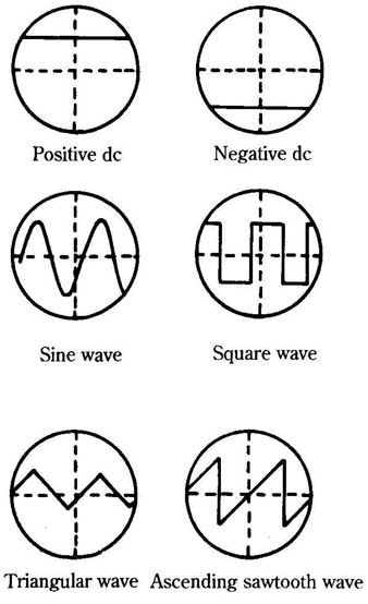
__3 Various waveforms can be displayed on an oscilloscope.
• Vertical gain—How much deflection from the base line a given input voltage will cause.
• Vertical position—The vertical position control allows the base line to be moved up and down on the CRT screen.
• Horizontal gain—How much deflection will be caused in the right/left dimension when an external signal is used to control the sweep frequency rather than the built-in oscillator.
• Horizontal position—Moves the displayed waveform from right to left on the CRT screen.
• Coarse frequency—Sets the range for the built-in sweep oscillator.
• Fine frequency—Sets the exact frequency of the built-in sweep oscillator.
• Sync—Synchronizes the display with another signal source.
• Intensity—Determines how bright the displayed line(s) will be.
• Focus—Adjusts the clarity of the displayed line(s).
Some oscilloscopes can simultaneously display two signals. This type of machine is called a dual-trace oscilloscope. Dual trace is extremely useful for comparing input and output signals or signals from different parts of the circuit being tested.
- Positive dc
- Negative dc
- Sine wave
- Square wave
- Triangular wave
- Ascending sawtooth wave
Signal tracer:
A signal tracer is basically an amplifier and output device (such as a speaker) that is used to indicate whether or not a signal is present at the stage of the circuit currently being tested.
Signal injector:
A signal injector is the reverse of a signal tracer. It allows you to insert a known signal into a given circuit stage to determine if it’s working properly. Signal injectors are available for both audio (AF) and radio (RF) frequencies.
Function generator:
A function generator is a multiple-waveform oscillator or signal generator. It can produce a clean, known signal at a wide variety of frequencies. If you feed a known signal to the input of a suspected circuit, you can examine the output signal with an oscilloscope to determine what if any distortion has occurred in the circuit being tested.
Frequency counter:
A frequency counter is used to measure the frequency of an ac signal. It usually has an input stage that converts the input waveform to a clean rectangle wave that can be reliably recognized by the digital circuitry within the frequency counter.
Capacitance meter:
A capacitance meter is used to determine the value of an unknown capacitor. It can also be used to check old capacitors for leakage and other problems, or to locate stray capacitances within a circuit. Most capacitance meters work by charging the unknown capacitor to a specific level, and then measure the time it takes for the capacitor to discharge. For more information on the time constant of a capacitor, refer to section 6.
Other test equipment:
Other pieces of test equipment are manufactured for various special purposes. The ones discussed in this section are the most widely available and generally useful. A technician’s workbench should also include a good variable-output power supply.
Common problems:
Every problem that crops up in electronic circuitry is more or less unique. Nevertheless, there are some fairly common sources of problems that you should be familiar with.
A resistor can change its value with age. This problem is likely to occur if an overvoltage or physical jolt has damaged the resistor. If you suspect a resistor problem, check for resistors that are discolored, or look burnt. Also watch out for tiny hairline cracks. These cracks might not be readily visible. Often a light tap with a screwdriver will cause a cracked resistor to break apart, but a good resistor won’t be harmed.
Cracks can also cause problems in capacitors. Especially watch out for ceramic disc capacitors that often tend to crack near their leads. Electrolytic capacitors often become leaky or their electrolyte might dry up as they age. If you see a whitish powder around an electrolytic capacitor, the powder is probably dried electrolyte. Usually, however, this kind of fault won’t be visible to the naked eye. Test equipment will have to be brought in to locate the culprit.
Of course, if the insulation between windings of a coil gets damaged or chips off, the inductor will appear to change the number of turns in the coil as adjacent turns short together. A short will cause the inductance to change.
If a PC (printed circuit) board is used, a tiny hairline crack might cause an open circuit. Similarly, because the copper traces are closely spaced, a scrap of wire or solder could land between adjacent paths and cause a short. Stray capacitances, inductances, and resistances might crop up when a new circuit is built, or they might appear in a formerly working circuit when one or more components goes bad or changes value.
Of course, active components can also go bad. Tubes often need to be replaced. Semiconductors are more reliable, but they can be damaged by hard physical jolts, runaway current, over voltages, or excessive heat. Special-purpose transistor testers are widely available. Basic semiconductor junctions (in diodes and bipolar transistors) can also easily be tested with a VOM. The resistance section of the VOM is used for this. Remember that an ohmmeter puts out a specific test voltage and measures the drop across the unknown resistance. If the polarity is applied to the semi conductor junction in one direction the ohmmeter will indicate a very low resistance. Reversing the polarity will cause a much larger resistance reading. For a bipolar transistor, measure between the emitter and the base and between the base and the collector.
In most cases the semiconductor component being tested will have to be re moved from the circuit because the rest of the circuit might have additional resistances in parallel with the junction, which could significantly change the readings.
ICs are treated as black boxes. If the signals at all of the input pins are correct, but one or more of the output signals is wrong, it might be reasonable to assume that the IC is bad. Watch out though—some circuits can really fool you. If the in put impedance of the next stage has changed due to some defect, the difference in the loading could cause the output being measured to be misread by the meter or oscilloscope.
Especially watch out for signs of any previous repair attempts. A lot of people who don’t really know what they are doing often attempt to repair electronic equipment, and their repair might have caused additional problems. A component can be physically damaged or installed with the wrong polarity. A thin lead or wire might be broken. PC board traces might be chipped or shorted.
A major headache is the cold solder joint. A cold solder joint happens when an air bubble has formed under the solder, making an unreliable connection. If a solder joint does not look smooth or shiny, suspect a cold solder joint. Unfortunately, the visual test is not always helpful. Many cold solder joints look just fine, but the electrical connection might be poor, exhibiting an open circuit or a high resistance, or (most frustrating of all) an intermittent connection.
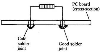
__4 Cold solder joints might not be visually apparent, but they can
result in poor electrical connections and cause many problems. Cold solder
joint; Good solder joint; PC board, (cross-section)
A cold solder joint will usually cause problems right away, so the problem most commonly comes up right after a circuit is constructed or repaired. If you suspect a cold solder joint, it might be a good idea to simply reheat all of the solder joints in the area, just to be sure.
Occasionally a cold solder joint won’t cause problems until the equipment has been in use for months or even years. They are not terribly common in commercially available equipment, but they do occur from time to time.
The bane of any technician’s existence is the intermittent defect. An intermit tent defect comes and goes. In some cases you can cause the problem to appear so you can troubleshoot it by simulating specific environmental conditions (high or low ambient temperatures are frequent culprits). All too often, the equipment will refuse to misbehave for the technician, and you can’t very well locate a problem that isn’t there when you’re looking.
Often a technician will operate the equipment under extreme stress to force the intermittent fault to become permanent so that it can be easily pinpointed. This practice is rather risky unless you know what you are doing and are very careful. How ever, the component causing the intermittent problem is presumably weaker than any of the good components, so it should fail completely before any other components are damaged.
-Flowcharting-
If you are servicing an electronic circuit with just a dozen components or so, you can take a brute-force approach and just test everything. But this approach would be highly impractical for any circuit with any degree of complexity. A television set, or a computer, or a VCR (to suggest just a few examples) can contain hundreds, perhaps even thousands of components. It would not be at all reasonable to attempt to test everything in such a device.
If you are attempting to service a given piece of equipment, it must be exhibiting symptoms of some sort. That is, it’s presumably not functioning properly in some way. The malfunction might be simple (a specific indicator light isn’t going on), or it might be global (the entire device doesn’t work at all). Often there are multiple symptoms that might or might not be related ( For example, a TV set might have no sound and a compressed picture). Whatever the symptoms might be, they always provide important clues for servicing the equipment in question.
An electronics technician thinks about the symptoms logically, and tries to imagine what could possibly be causing the observed symptoms. This reasoning will tell him or her what types of tests are most likely to provide worthwhile results. Often many different causes could be behind a given symptom (or group of symptoms), so, if possible, try to list these potential causes in order of probability. Make the most probable tests first, you are less likely to waste time with fruitless tests that way.
When there are multiple symptoms, they might be due to entire separate causes, but it’s relatively unlikely for a circuit to simultaneously develop two (or more) entirely unrelated defects. It can happen, but it’s more likely that all the observed symptoms stem, directly or indirectly, from a single root cause. Use logical thinking to determine what could be causing all the observed symptoms and test for that first. Only if you run into a dead end on the common cause should you start Troubleshooting the observed symptoms independently. Again, you will save a lot of wasted time in the long run.
A very useful Troubleshooting technique that is often ignored is the flowchart. A flowchart is a simple block diagram graph of the equipment to be serviced. The functions of the various subcircuits and their interconnections are shown. This information helps the technician determine what subcircuit(s) is most likely to be causing the observed symptoms. A very simple flowchart for a typical color television set is shown in Fig. __1.
Some experienced technicians might be able to hold a full flowchart entirely in their heads, but for most, actually drawing out a flowchart will be helpful, especially in more difficult servicing jobs. There is no reason to be concerned about precise dimensions or perfectly straight lines. Your flowchart is not for publication, it’s for your own convenience. If it’s neat enough for you to read it, it’s good enough. It often helps just to see the circuit functions broken down in visual form like this.
As a rule of thumb, it’s a good idea to always consider the power supply a possible culprit for virtually all symptoms. Incorrect supply voltages, or noise on the power lines can cause a lot of surprising results in many circuits.
The shapes used in your flowchart don’t really matter, although it’s probably useful to use different shapes for certain common types of subcircuits. For example, using a circle for a signal source (such as an oscillator), or a triangle for an amplification stage can make the flowchart easier to read at a glance.
Often each section in the original flowchart will include dozens of components, and can often be broken down to multiple subcircuits. It will usually be helpful to break down any suspected section into more detailed subsections. For example, if you are working on a television set with problems in its sound, but the picture is okay, you’ll probably only want to look closer at the audio amplifier section. Draw a more detailed sub-flowchart for this section of circuitry, as shown in Fig. __ 5. You don’t need to identify the subcircuits in any flowchart section where no defect is suspected or likely. You don’t expect to do any testing in that part of the equipments circuitry.
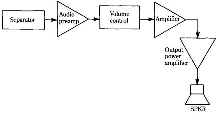
__5 In narrowing down the problem, it’s often helpful to draw a more
detailed block diagram of the suspected stage(s). Output power amplifier
power.
The next step in creating a Troubleshooting flowchart is to identify the key components in any relevant stages, especially ICs, transistors, transformers, relays, etc. The identification will help focus you in on that components and connections you will want to test, and which probably aren’t worth bothering with, because they are unlikely to be defective, given the symptoms observed. For example, in a TV set with sound problems (and no other symptoms), there would be little point in testing the picture tube or the color burst oscillator.
Write the appropriate component identifications in flowchart, as shown in Fig. __6. This will be easiest to do by comparing your flowchart with the schematic included in the servicing data. It’s very difficult to service a complex electronic circuit without a schematic unless you have a great deal of experience with that particular type of equipment.
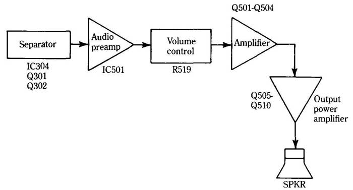
__6 The next step is to identify the key components in the suspected
stage.
You don’t have to list every single resistor or capacitor. Just list the key components, especially active components, and controls. Any passive component in the immediate vicinity of these key components is obviously part of the same subcircuit. You might occasionally test a resistor or two that isn’t really part of the subcircuit you thought it was, but this will be fairly rare, and won’t waste as much time as getting overly detailed in the flowchart.
Notice that there is little point in worrying about the key components in any subcircuits you have already eliminated in the Troubleshooting process. If you know the defect must be somewhere in the audio amplifier of the TV, and the video amplifier, and the tuner are probably okay, so you don’t care about locating their key components. A little logic and a good flowchart will tell you what tests you should perform to track down the defect(s) causing the observed symptoms.
-Servicing without a schematic-
All too often it’s necessary to service a piece of electronic equipment for which no schematic diagram or other relevant technical literature is available. Clearly this problem increases in seriousness with the complexity of the equipment in question.
The key to solving such problems is to first mentally break up the circuitry into functional blocks. For moderate to complex equipment, it would probably be a good idea to actually draw out a block diagram. For some relatively simple circuits, you might be able to hold the information in your head. Of course, skill in this type of task comes only with experience. Although it will get easier as you gain practical servicing experience, and theoretical knowledge, it will never be truly easy, which is why you should first make every attempt to find a schematic or other service literature if at all possible.
In many cases, there will be some things you simply won’t be able to figure out on your own, so if you don’t have a schematic, you may be out of luck on some special features and calibration procedures, and the like. Still, there is much you can do with most electronic equipment without a schematic. Just remember, this approach is one of last resort. A schematic will make your job 1000% simpler.
Now, it’s difficult to look at a section of circuitry and determine what it’s supposed to do. Exotic, unfamiliar, or unmarked ICs further complicates the analysis. An amplifier IC looks just like a timer IC, which looks just like a digital flip-flop IC. Obviously, you won’t get very far with your block diagram from just staring at the circuit board. You have to use some logical thinking.
Don’t start from the circuit itself, but from the intended function of the equipment. What circuit stages would be required to do the job? In other words, you have to think like a circuit designer. Make a note of any and all controls on the equipment. The controls will provide valuable clues to circuitry functions. Also, components near the control are presumably part of the same subcircuit.
Don’t forget “obvious” stages. Almost any piece of electronic equipment will have a power supply subcircuit of some sort. For some portable equipment, the power supply will be nothing more than some batteries and perhaps a diode or two to protect against possible incorrect installation of the batteries. All you really have to check is the battery voltage and the condition of the diodes, mainly that they are not shorted out.
AC powered equipment will generally have a more complex power supply stage. First check for blown fuses or circuit breakers. Of course, you should make sure the equipment is plugged in. In practice, field technicians often get a service call when there was nothing wrong except the equipment had somehow been unplugged.
Most ac power supplies have a power transformer of some sort. The secondary winding (or windings) of this transformer will be connected to either one or more rectifier diodes or a voltage regulator IC. (In some circuits, both can be encountered). In either case, there will probably be some filter capacitors too. Usually at least some of these filter capacitors will be fairly large electrolytics, which not only have large capacitance values, but also are physically large. The transformer and the large filter capacitors usually make it relatively easy to identify and isolate the power supply circuitry.
A voltage regulator IC usually resembles a slightly oversize power transistor with three leads (in, out, and common). Sometimes a bridge rectifier is used instead of four separate rectifier diodes. This component will look like a square block of plastic with four leads. Internally, it’s simply four matched rectifier diodes encapsulated in a single convenient housing.
Locating the power supply will also provide you valuable clues in tracing the remainder of the circuitry. Find the ground or common connections. Identifying the supply voltage and common connections to any ICs will help cut down the possibilities for identifying the inputs and outputs.
In most electronic equipment, some sort of signal will probably pass through the system. Attempt to locate the point of origin for the main signal. If the equipment uses some sort of external signal source, this process should be relatively easy. Just find the input jacks (or other connectors). For example, an amplifier in a stereo system might take its input signal from a tape deck or a CD player. In a TV or a radio, the main signal originates at the antenna terminals. In other equipment, the main signal can be internally generated. More often than not, the signal comes from an oscillator stage of some sort. An oscilloscope would be a big help in locating a the point of origin of a signal and tracing its passage through the circuitry.
If the equipment you are working on uses signals in the audible range, you might be able to use a signal tracer probe, which can be a simple audio amplifier and speaker with a suitable probe at its input. Refer to section 9 for more information on signal tracing.
Pay close attention to any controls, as they will give you clues as to the function of that section of the circuitry. For example, a volume control, or gain control is almost certainly part of an amplifier stage of some sort. (But always remember, that stage might perform additional functions besides simple amplification.)
Servicing electronic equipment without a schematic is not easy, and should be avoided if at all possible. But sometimes it’s necessary. Just remember, the task is not truly impossible. Work as slowly and logically as possible. Take as many measurements as you can. It’s hard to tell if any single measurement is correct or not, when you look at it by itself. But if you take many measurements throughout a circuit, one or two might stick out like a proverbial sore thumb. Try to relate the odd seeming measurement(s) with the symptoms exhibited by the malfunctioning equipment. If , for example, the problem is excessive distortion, if one stage of the circuit suddenly shows a lot of mysterious, and seemingly unnecessary signals, that might possibly be the source of the distortion. Try to think if there could be any possible reason for the odd signals to be part of the intended design of the circuit. If not, what would have to be done to eliminate them? Does that clear up the malfunction, or does it create new problems?
For obvious reasons, servicing without a schematic or other relevant technical literature or data is not at all recommended for inexperienced electronics technicians. To get some experience, try your hand on some noncritical equipment, especially equipment someone else has thrown out because of some defect.
Another way to learn to do such “data-blind” servicing would be to first attempt diagnosis on a piece of equipment before you look at the schematic and other Troubleshooting data. Don’t actually do anything to the circuitry at this point—just at tempt to figure out how it’s supposed to work. Then refer to the available servicing data and see how close you came. The first few times you try, you will almost certainly be way off more often than not, but you will become more skilled with time.
Remember that servicing electronic equipment without a schematic or other appropriate servicing data is always a course of last resort. Only a very foolish technician would ever consider attempting a repair without consulting any and all schematics or troubleshooting materials. The only possible exception would be if he has worked on one particular model of equipment so often that he has the relevant servicing data memorized. Even then, it’s probably unnecessarily risky to rely too heavily on human memory. Keep the schematic and other materials handy so you glance at them occasionally, just to be sure.
--QUIZ--
1. How can a block diagram be used in troubleshooting?
A To determine specific operating voltages
B By visually comparing it with the circuit under test
C By narrowing down the stages that could cause the fault in question
D By allowing the technician to systematically check out each stage of the circuit
E None of the above
2. If a television set doesn’t work at all (dark screen, no sound) which stage is the most likely source of the problem?
A The power supply
B The video amplifier
C The tuner
D The color killer
E None of the above
3. Which of the following voltmeters would give the most accurate readings?
A 20,000 WV VOM
B 11 M-ohm VTVM
C 1000 ohm/VVOM
D 50,000 WV VOM
E None of the above
4. Which of the following can not be measured with a standard VOM?
A Current
B Inductance
C Resistance
D Voltage
E None of the above
5. Which of the following is an advantage of a VTVM over a VOM?
A More portable
B Measures current
C Less expensive
D Operates with less heat
E None of the above
6. What should be the relationship between a meter input resistance (Rin,) to the resistance the voltage drop is being measured across (R1)?
A R must be much larger than Rm
B They should be approximately equal
C R must be much smaller than Rm
D None of the above
7. Which of the following is the second most important piece of test equipment for the average electronics technician?
A Oscilloscope
B Frequency counter
C Signal injector
D Capacitance counter
E None of the above
8. Which control on an oscilloscope is used to calibrate the displayed input voltage a specific distance over or below the baseline?
A Coarse frequency
B Vertical gain
C Horizontal gain
D Horizontal position
E None of the above
9. Which of the following is not a common defect in a resistor?
A Changed value
B Burnt
C Cracked
D Leaky
E None of the above
10. If an ohmmeter measures a small resistance when it’s hooked up across a semi conductor diode, what would happen if the polarity of the ohmmeter leads are reversed?
A. A higher resistance will be indicated on the meter
B. The same resistance will be measured
C The semiconductor junction will probably be damaged
D. It doesn’t matter—the diode must be bad
E. None of the above.
<< >>