AMAZON multi-meters discounts AMAZON oscilloscope discounts
..
This section deals with the problems and solutions of dealing with discrete components.
==Detecting thermal drift in resistors==
Thermal drift in resistors is one of the most common and annoying troubles in all kinds of electronic equipment. It causes such symptoms as “it plays for an hour and then acts up.” If a carbon resistor changes in value as it heats up, it changes the circuit characteristics.
The time constant will tell you a lot. If the trouble shows up inside of 15 minutes, it’s probably a result of self-generated heat in a resistor, heat generated in the resistor because of the current it’s carrying. Heat occurs in plate-load circuits, voltage-dropping resistors, etc. If the trouble takes an hour or so to appear, the resis tor is being affected by heat traveling through the metal chassis or from a hot component close by.
The best test for a suspected resistor is to heat it up artificially and watch for the trouble to appear. For example, if you had a long-time-constant sync trouble, you could turn the set on, adjust it for correct operation, and then apply heat to each of the resistors in the sync circuit. Place the tip of a soldering iron on the body of each resistor, hold it there for 45 to 60 seconds, and watch for the sync trouble on the screen. Normal operating temperature in a TV set is 120 to 130°F. The tip of a soldering iron runs about 600°F, so don’t hold it on the resistor too long—just long enough to get the resistor warmer than normal or too hot to hold a fingertip on it.
If the resistor has a tendency toward thermal drift, this test will reveal it.
The high-value (6, 8, 10, and 20 M) resistors found in age circuits are frequent offenders. You can find the guilty resistor by turning on the set, heating up each resistor in turn, and watching the screen for any sign of the original trouble. There might be more than one defective resistor in a given circuit, so check them all.
==Checking and repairing potentiometers==
A potentiometer is simply a manually controlled resistor. The term is often informally shortened to pot.
The effective resistance of a potentiometer is determined by the position of a rotating shaft. Fig. 1 illustrates the internal construction of a typical potentiometer. The two end terminals are connected to either end of a U-shaped resistive element. The control shaft is connected to a sliding element. Rotating the shaft moves the slider in one direction or the other along the length of the resistive element, creating a changing resistance. Let’s assume that the slider starts off as close as possible to end terminal A and is slowly moved toward end terminal B. The resistance be tween the center terminal and end terminal A increases, while the resistance between the center terminal and terminal B de creases by a like amount. The resistance element can be designed so that the resistance changes linearly ( Fig. 2) or logarithmically ( Fig. 3), depending on the requirements of the specific application.
A trimpot, or trimmer potentiometer works in much the same way, except the control shaft can be replaced with a screwdriver adjustment. This adjustment reduces the size of the component and is more secure for “set-and-forget” calibration controls.
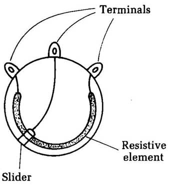
_ Fig. 1 Inside a potentiometer, a slider is moved over a resistive element.
Terminals; Resistive element

_ Fig. 2 (left) Some potentiometers have a linear response. (right) Fig. 3 Other
potentiometers have a logarithmic response.
You occasionally might encounter a slide pot. This component is basically the same as a standard potentiometer, except the resistive element’s normal U-shape has been straightened out into a line. The control shaft does not rotate; instead, it’s moved back and forth over the straight-line resistive element. A slide pot is used in applications in which the position of the control shaft is to be directly visible, instead of indicated by markings on a dial. For example, slide pots are widely used in audio mixer consoles and graphic equalizers.
Some potentiometers, especially trimpots, have just two terminals, instead of the more common three just described. In such cases, there simply is no connection with one of the ends of the resistive element—there is just the center terminal and one of the end terminals.
A three-terminal potentiometer can easily be used in any application calling for a two-terminal potentiometer. Simply leave one of the end terminals disconnected and unused in the circuit. Some technicians prefer to short the unused end terminal to the center terminal. This method won’t affect the operation of the potentiometer in any noticeable way.
Testing potentiometers:
Testing a potentiometer is usually fairly simple. You can use the ohmmeter section of any multimeter. It doesn’t much matter what type of multimeter is used, as long as it’s reasonably accurate in its coverage of the required resistance range.
As with any test of resistances, testing a potentiometer in circuit can give inaccurate readings because of parallel resistances in the circuit. When in doubt, temporarily break the connection between one of the test terminals of the component and the circuitry.
On a three-terminal potentiometer, first measure the resistance between the two end terminals. You should get the potentiometer’s full rated resistance. The setting of the control shaft should have no effect at all on the resistance read between the two end terminals. For example, if you are testing a 10K potentiometer, you should get a reading of 10,000 12, more or less. Don’t be too concerned about the exact resistance value. Most potentiometers are not precision components when it comes to their full-scale resistance, nor do they need to be in the vast majority of practical applications. As long as the resistance reading you get is in the right ballpark, you can assume that the potentiometer has passed this test.
The more important test is to monitor the resistance from the center terminal to one of the end terminals. It usually doesn’t matter which one you use. (Of course, for a two-terminal potentiometer, there is no choice, since there is only one end terminal.) If possible, clip the test leads of your ohmmeter in place on the potentiometer’s terminals to leave your hands free. Slowly and smoothly rotate the control shaft while watching the ohmmeter’s pointer or display. As the control shaft is rotated toward the end terminal being used in the test, the resistance should decrease. Rotating the shaft away from the monitored end terminals should cause an increase in the resistance.
Rotate the control shaft as smoothly as possible. The resistance reading also should change smoothly and evenly. (Re member that some potentiometers change their resistance in a linear fashion, while others have a logarithmic response.) If the resistance jumps around, jiggles up and down, makes large skips, or gets “stuck” at a specific value over a few degrees of the shaft’s rotation, a problem is indicated. Such erratic readings generally indicate that the resistive element is dirty or pitted, resulting in unreliable operation in the circuit. In some cases, there might be static or a crunching noise in audio circuits as the potentiometer’s control shaft is rotated.
Cleaning potentiometers:
Slide pots are particularly prone to getting dirty because their construction inevitably leaves the resistive element more exposed to external contamination than in most standard round pots. To cure this problem, spray in some cleaner/lubrication spray, which is sold by almost any electronics parts store. It’s often called “tuner cleaner.” It’s an aerosol spray can, with a small straw that can be connected to the nozzle to finely direct the spray. Direct the spray into any openings in the body of the potentiometer and then work the control shaft back and forth over its entire range several times to spread the cleaning fluid over the entire resistive element. It’s a good idea to wait a couple of minutes to let the fluid dry, but this is rarely absolutely necessary. For a slide pot, you can easily insert the spray in the slot for the control slider’s back and forth path.
When in doubt, clean all potentiometers, just to be on the safe side. Unless you use a ridiculous amount of spray, doing so will never hurt the circuit and even if dirt isn’t causing the current symptoms, it’s still likely to clean up dirt that hasn’t built up to a noticeable problem yet. Cleaning the potentiometers is a form of preventive maintenance.
A lubricant in the cleaning spray is usually helpful, but a few components might be damaged by lubrication. When in doubt, use an unlubricated cleaning spray, even though it won’t always be quite as effective.
If cleaning the potentiometer does not help, the resistive element might be badly pitted and permanently damaged. Try substituting a potentiometer that is known to be good. If the problem clears up, discard the original potentiometer as defective, and solder in a permanent replacement.
Many potentiometers, especially those used as volume controls, come equipped with a switch mounted on the back of the component. When the control shaft is rotated past a specific spot (usually near one end of its range of movement), the switch is activated. Sometimes these potentiometer switches develop problems. They might not make proper contact, or they might get stuck in one position or the other, ignoring the rotation of the potentiometer’s control shaft.
Visually inspect the switch mechanism. Sometimes you might see that something is slightly bent. Use a pair of small needle-nose pliers to move it back into place. Be very careful not to do more damage.
Cleaner/lubrication spray will often solve poor switch contact problems. Spray some of the cleaning/lubrication solution into the switch mechanism and turn it on and off several times. If this doesn’t work, you will probably have to replace the switch, which often entails replacing the entire potentiometer unit.
Stuck switches are usually unrepairable. The damage is probably permanent. It won’t hurt to try to bend some small part back into place within the switching mechanism (if accessible), or even to try cleaning the switch unit, but don’t get your hopes up too high, or spend a lot of time at it. You will probably end up having to replace the defective switch, which often means replacing the entire switched potentiometer unit.
==Capacitance testing==
There are only two things you need to know about almost any paper, ceramic, or mica capacitor: Is it open, or is it leaky or shorted? Measuring the capacitance value is seldom necessary, since this information normally is stamped or color-coded on the capacitor itself. Capacitors of these types are not likely to shift in value, so the real question boils down to whether a capacitor is good or bad.
A capacitor tester is handy for determining whether a capacitor is open. Hook it up and turn the dial rapidly from one end to the other, past the nominal value of the capacitor. If the tuning eye on the tester opens at all, the capacitor is not open.
Make the same check with an ohmmeter for values larger than 0.01 uF by touching the ohmmeter across the capacitor and watching for the charging kick. (Smaller values give a charging kick, too, but it’s too small to show on the meter.)
Next, and most important, check the capacitor for leakage. A dead short or high leakage can be caught with the ohmmeter. If the ohmmeter shows any deflection on the highest ohms range available, the capacitor is bad. For very critical applications, such as audio coupling capacitors in vacuum-tube amplifiers, you need a test instrument that reads very small leakage. Even a leak age of 100 M is enough to cause trouble in a coupling capacitor.
The fastest test for a possibly open capacitor is to bridge an other one across it. If you suspect oscillation is caused by an open bypass capacitor, For example, bridge it. If the oscillation stops, you have found the trouble. If a coupling capacitor is suspected, you can test it in two ways: check for the presence of signal on both the input and output sides of the capacitor; or bridge another capacitor across it — if the signal now goes through, the original is open. If a capacitor opens, it has the same effect as taking the capacitor completely out of the circuit. So, replace it by bridging, and see if the trouble stops.
There has been a lot of development in capacitance meters in recent years. Newer devices check for opens and shorts, measure leakage, and display the capacitance value directly. These de vices and other new types of test equipment were discussed in section 1.
Electrolytic capacitors:
Electrolytic capacitors, unlike paper capacitors, can change value by drying up. A dry electrolytic is not dry any more than a dry-cell battery is. If the electrolyte evaporates in either one, it stops working. A battery dies, and a capacitor opens completely.
With electrolytics, the best test is again, “How well do they work?” If the service notes specify that a power supply should have 275 V at the rectifier output and you find only 90 V to 100 V, the input capacitor is very likely open. Bridge it with a good one; if the voltage jumps up to normal, that was the trouble. If the ripple or hum level is given as 0.2 V p-p at the filter output and your scope shows 10 V to 15 V p-p there, bridge the output capacitor. If the ripple drops to within the proper limits, that capacitor was open.
For bridging purposes, the test capacitor does not need to be an exact duplicate of the original. It can be much larger or smaller in value, but it must have a working voltage able to stand what ever voltage is present in the circuit. It’s not a good idea to bridge electrolytics in transistor circuits with the amplifier on. The charging-current surge of the test capacitor can cause a sharp transient spike in the circuits, which can puncture transistors. So, to bridge-test transistors sets, turn the set off, clip the test capacitor in place, and then turn the set on again. With the instant starting of transistor circuitry, this won’t waste any time.
If you find one unit in a multiple-type electrolytic to be bad, replace the whole can. Whatever condition existed inside that can to make one unit go out will eventually cause failure of the rest because they’re all parts of the same assembly. To avoid an almost sure callback, change the whole thing at once.
Finding the value of an unknown capacitor without a capacitance meter:
If you don’t have a modern capacitance meter handy, there is still a fairly quick way to find the value of an unknown capacitor.
Note: This method isn’t accurate unless you have a precise ac voltmeter or calibrated scope and an accurate test capacitor. The method is handy for finding the values of those odd mica capacitors that everyone has around and can’t read the color code on.
Put the capacitor in series with a known capacitor, as shown in Fig. 4, and apply an ac signal voltage across the two. Measure the voltage across the known capacitor, then measure the voltage across the unknown capacitor. The voltage ratio will give you the ratio of the capacitances.
What you’re doing is putting two reactances in series across an ac-voltage source. The result is a voltage divider that works the same way as two resistors in series across a dc source. Suppose, for instance, that you put 11 V at 1,000 Hz across a series combination consisting of a .005 uF capacitor and an unknown capacitor. Sup pose then you measured 10 V across the unknown and 1 V across the known. The voltage ratio for the unknown and known capacitors is 10:1, and so is the ratio of reactances. The ratio of capacitances is just the opposite, or 1:10, because the reactance of a capacitor is inversely related to the capacitance: As capacitance increases, reactance decreases, and vice versa.
In the example given, the unknown capacitor has a value one-tenth as great as the known capacitor, or .0005 Re member, a voltage ratio of 10: 1 means a capacitance ratio of 1 : 10. i you prefer, you can work with reactance values, reading them from a table and then using the table to find the corresponding capacitance values.
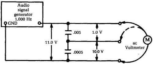
_ Fig. 4 A capacitor’s value can be approximated with a test hook-up like
this.
Testing capacitors with a scope:
An oscilloscope is another handy tool for checking capacitor problems. Generally the standard low-capacitance probe is sufficient, although in some cases, a demodulator probe is useful.
To test the capacitor, adjust the scope for maximum sensitivity on vertical gain. Then touch the probe tip to the hot side of the capacitor to be tested. Interpretation of the scope trace depends on the capacitor’s intended application in the circuit. In most circuits, capacitors are used for bypassing, filtering, or coupling.
A bypass capacitor is always grounded at one end. Unwanted ac components of a signal are shunted to ground. In this test, you want to determine that the ac components have indeed been eliminated from the signal.
A filter capacitor is really very similar to a bypass capacitor, although it’s usually somewhat larger in value. A filter capacitor’s function is to shunt unwanted signals, such as ac hum or RF signals, to ground. It’s easy to determine if these components are present in the scope trace.
A coupling capacitor, or blocking capacitor, is placed in the circuit to pass an ac signal but to block any dc component in the signal. Check the scope trace to make sure the ac signal is centered around 0 and is not riding on a DC voltage.
==Testing variable capacitors==
Variable capacitors are not used in modern electronics nearly as often as they once were, but you still might encounter them from time to time, especially in older radio tuners. In a typical variable capacitor, a set of movable plates, or rotors, are moved either directly via a tuning knob, or indirectly with a dial cord and a system of pulleys. These rotors are intermeshed with a second set of fixed-position plates, known as stators. The rotors move with respect to the stators. The air between the two sets of plates acts as the capacitor dielectric, so the relative positioning of the two sets of plates determines the effect capacitance of the component at each setting.
Test the resistance from any of the rotor plates to the metal frame of the variable capacitor. If the circuit is mounted on a metallic chassis, the component might or might not be insulated from the chassis. You should measure a dead short, or 0 Ohm.
Disconnect the wires connected to the stator terminals and measure the resistance from each stator plate to the rotor and/or the unit’s metal frame. You should get an open circuit reading. The ohmmeter should indicate infinity, or a very, very high resistance. To be doubly sure, it’s a good idea to make this test at each extreme of the tuning shaft’s range; that is, once with the plates fully meshed, and once with them as opened up and far apart as possible. You also should get an infinity reading between individual stator sections.
In servicing equipment with variable capacitors of this type, you also must watch out for mechanical defects. It’s usually very easy for one or more of the capacitor’s plates to get bent. A bent plate can restrict the movement of the tuning control. It also can create a short circuit between the rotor section and the stator sections, causing noise or a partial or complete loss of signal. In some cases, turning the tuning control will have no apparent effect be cause of such a mechanical short circuit.
These tests are only for open-air types of variable capacitors. They are not appropriate for some other types of variable capacitors.
==Testing inductors==
A coil, or inductor, is basically a pretty simple component. It’s really nothing more than a length of wire wound in a coil shape around a core of something. (In some cases, there is an air core. That is, there is nothing at the center of the coil except empty air.) This type of component isn’t used in modern electronics nearly as much as it used to be, but it’s still far from uncommon. You won’t run into as many coils as capacitors or resistors, but the odds are, you will run across some in the electronic equipment you are servicing.
The basic unit of inductance is the henry (H), or, more commonly, the millihenry (mH). One henry equals 1,000 millihenries. Unfortunately, standard electronic test equipment cannot measure inductance values directly (see the next section of this section). Fortunately, you can do some crude, but effective, good/bad tests with an ohmmeter to find most common faults with this type of component.
As with most component resistance readings, you probably will have to disconnect at least one end of the inductor from the circuit to avoid the effects of parallel resistances that can confuse the picture. However, this problem is generally less significant for coils than for other types of electronic components because the resistance of a typical inductor is so low that it will probably be the major factor in determining the total effective parallel resistance. Still, there are exceptions.
There are essentially three basic ways a coil can go bad: It can be open, there can be a short between windings, or there can be a short to the inductor coil.
Open coils:
Open coils aren’t very common, but they can happen. An open coil is just a break in the coiled wire, or more likely, in its leads, which connect it to the rest of the circuit. If you measure the resistance across the terminals of a coil and get an infinity (or very high) reading, then you have an open coil. In some cases, it might be worthwhile to take just a moment or two to see if you can locate the break visually.
In some cases of a broken lead, you can resolder it without too much trouble. Otherwise the coil is defective and must be re placed. In most practical servicing situations, there is little point in spending much time in trying to locate the actual break, since the odds are that it won’t be reparable.
Shorted turns:
It’s trickier to determine whether or not there are one or more shorted turns in an inductor. Most practical coils consist of many closely wound turns of fine wire. If some of the insulation chips off, melts, or is otherwise removed, the conductive wires of adjacent turns will touch, producing a short circuit, as illustrated in Fig. 5. The coil will act like it has too few turns, and therefore, it won’t function properly in the circuit.
If you know the nominal resistance of the coil in question, you can simply measure the resistance across the coil’s terminals. If you get an abnormally low resistance reading, then a short within the coil is probable. Replace the defective inductor.
The nominal resistance of coils often is included in service data or specification sheets. If it’s not, however, it’s a lot harder to determine what the correct resistance for the coil should be. Normally, it will be a very low value, since, as far as dc current (and resistance) is concerned, a coil is nothing but along length of ordinary wire. A dc signal couldn’t care less that the wire is coiled, rather than straight. Any conductor has some finite resistance per foot. The longer the conductor, the lower the resistance. Shorted turns in a coil effectively shorten the conductor length.
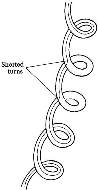
Fig. 5 Shorted turns in a coil effectively make it function like a smaller
inductance. Shorted turns.
If the circuit contains more than one coil, you might compare the resistance readings across each of them to see if they are reasonably similar. Don’t make too many assumptions. There is no guarantee that all similar-looking coils in a circuit have the same value. One might have 100 turns, while another might have 225 turns, so their resistance readings logically will be quite different. You can, however, sometimes make some reasonable guesses. For example, let’s say you have a circuit with four coils that look pretty much alike. When you measure the resistance across each coil, you get the following readings:
Coil -- Ohms
- A 51
- B 48
- C 11
- D 55
With these readings, I would certainly be suspicious of coil C, especially if the schematic indicates that all four coils should have similar inductance values.
Shorts in inductor coils
The third common type of defect in an inductor is a short to the core. This is mechanically similar to the shorted turn discussed earlier. One or more of the windings in the coil has lost some of its insulation for some reason, and since the turns of wire are pressed tightly against the coil, there is an electrical short circuit between the core and the exposed winding(s). Obviously, this is only a problem in an inductor with a conductive core, such as an iron core. You won’t encounter this type of problem with an air-core coil, of course.
You can determine if there is a core short by measuring the resistance between either terminal of the inductor and the core itself. Ideally, this resistance should be infinite. In most practical cases, you will get a finite, but very high resistance reading. A typical value will be over 25 M The exact winding to core resistance depends on the core material and configuration, as well as the quality of the insulation used in the construction of the inductor.
These same tests also apply to RF chokes, since this type of component is just a special-purpose coil. The term choke has more to do with the function than the actual construction of the component itself.
You can test a transformer in a similar way. A transformer is made up of two (or sometimes more) coils wound on a common core so their electromagnetic fields interact. Test the primary winding as if it was a simple coil. Then do the same with the secondary winding(s). Most transformers have just a single secondary winding, but some have more.
Test each secondary winding separately, but don’t get con fused by center taps. A center top is an extra terminal to permit circuit connection to a midpoint on the coil. A center tap is clearly shown in the standard schematic symbol for a transformer with a center-tapped secondary, as illustrated in Fig. 6. Fig. 7 shows a transformer with three secondary windings. Notice that one of these secondaries also has a center tap.
You also should test for electrical isolation between the primary and each secondary winding of a transformer. Measure the resistance between either end connection of the primary winding and either end connection of the secondary winding. (For a trans former with more than one secondary, repeat this test for each secondary winding.) You should get a very high (nominally infinite) resistance reading. If you get a resistance reading of less than 20 M-Ohm or so, suspect trouble. There might be a partial or total short between the windings, which will interfere with the correct operation of the transformer and could easily result in some dangerous conditions. A very low reading here is a clear indication that the transformer should be replaced immediately.
Don’t attempt to operate any electrical equipment with such a defective transformer. If you’re lucky, there will only be major damage to the rest of the circuitry. However, there is also a very real possibility of dangerous, and potentially fatal electrical shocks and/or fire.
One important exception to this last test. A special type of transformer, known as an autotransformer, uses the same coil for both the primary and the secondary, as illustrated in the schematic symbol shown in Fig. 8. Obviously, in this case you inevitably will read a very low resistance between the “primary” and the “secondary,” since they are just different points along the very same length of coiled wire.
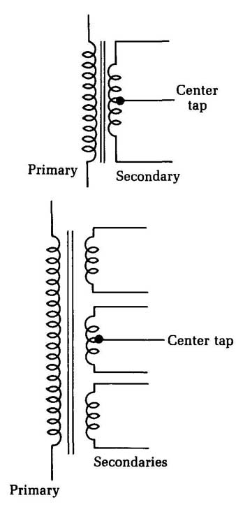
_ Fig. 6 (top) Some transformers have a center tap on the secondary winding.
Center; Primary tap; Secondaries
_ Fig. 7 (above) Some transformers have multiple, isolated secondary windings. This transformer has three secondaries, one of which is center tapped.
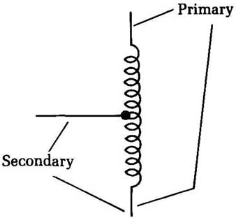
_ Fig. 8 An autotransformer uses the same physical coil as both the primary
winding and the secondary winding.
==Measuring inductance==
The question is often asked, “How can you measure inductance?” The best answer is, “ You can’t.” Inductance measurements, with common shop equipment, are a practical impossibility. You can figure it out by spending lots of time and doing a lot of mathematics, but the best advice we can offer is, “Don’t.”
In practical service work, there’s seldom a need to read the inductance of a coil or transformer in henrys or millihenrys. You are usually interested in just one thing: continuity. This is a simple ohmmeter test. All service data give the dc resistances of coils, and as long as your resistance reading on an inductor is within 5 percent of the specified value, the inductor is probably all right.
Only two things that can happen to an inductor: It can open completely (which is fairly easy to find), or it can develop shorted turns. In power transformers, etc., shorted turns give a very definite indication: smoke. In other circuits, such as output trans formers, shorted turns cause a drastic loss of output. You can locate a shorted turn by elimination tests and power measurements.
Flybacks are a special case; they act more like tuned circuits than ordinary transformers do. You can test them with a special instrument that connects the coil into a circuit and makes it oscillate. Read the Q of the coil on a meter. However, you can check flybacks for shorts by reading the cathode current of the horizontal-output tube and then disconnecting all loads, such as the yoke and damper circuits, and reading again. If the cathode current is far above normal, the flyback is internally shorted. When the loads are disconnected, the current should drop to about one fourth its normal full-load value.
To get an inductance of any particular value, there’s one easy way: buy it. You can wind coils all day, trying to get an 8.3 uH choke, but if you call your distributor, you can have a choke coil with exactly 8.3 uH in a few minutes. Coil and transformer makers have a tremendous selection of coils in all conceivable sizes, listed by their inductance, mounting style, etc. By far, the easiest way to work with inductors is to go buy an exact duplicate when you need it.
==Shorted power transformers==
A common source of problems in electrical circuits is the short circuit. The trick is in determining just where it is. It’s usually somewhere in the load circuit, but infrequently, the problem might be in the power transformer. You could waste hours going through every single component in the load circuit and tearing your hair out because everything checks out fine, when the problem is really in the power supply itself. Be aware of this possibility, although it’s definitely the exception, rather than the rule.
A handy “quick-and-dirty” test is to disconnect everything from the secondary (or secondaries) of the power transformer. When you do so, the transformer should drive no external 1o at all. Next, plug in the device and wait 10 to 20 minutes. Feel the case. Is it abnormally warm? Some heat is to be expected, but if it’s abnormally warm under these conditions, the power trans former is probably shorted. If the case is too hot to touch comfort ably, there is definitely a problem with the power transformer.
You’ve narrowed down the problem to the power trans former, since nothing else is getting power, so no other component can be the source of the excessive heat. Nor can the transformer be overloaded, since it’s running with no load at all, so the current drawn from its secondary winding(s) should be zero. The only possible cause for this heating is some shorted windings within the transformer itself. The transformer must be replaced or rewound.
You can use a dynamometer-type wattmeter for a more exact test. A good power transformer with no load should give a very small rating, only 5 W or less in a large power transformer. This small wattage is a result of the normal iron loss effects within the transformer, which is why some heat is inevitable. A higher watt age reading with no load is a clear indication of trouble.
Not all wattmeters will work properly for this test. You must use a dynamometer type, with both a voltage coil and a current coil. Such a wattmeter will have four terminals, instead of just two. If you don’t have a suitable wattmeter handy, you can make a simple, crude, but reasonably effective wattmeter with an ac voltmeter (the ac volts section of your multimeter) and a 1 power resistor in series with the ac circuit to be monitored.
Checking the turns ratio of a transformer:
A power transformer consists of two coils closely wound around a single core. Passing an ac voltage through one coil (the primary) will induce a proportionate ac voltage in the other coil (the secondary). Note that some transformers have multiple secondary windings with a single primary. The induced voltage across the secondary winding might be the same as the input voltage applied to the primary winding, but usually it will be different. The relationship between the input and output voltages is determined by the relative number of turns in each winding. There are three basic combinations:
Type | Output voltage compared to input voltage | Secondary turns compared to primary
- Step-down transformer | lower| fewer
- Isolation transformer| same| same
- Step-up transformer| higher | more
The turns ratio is defined by the number of turns in the primary winding divided by the number of turns in the secondary winding. Since this ratio will correspond to the proportional volt ages, you can also define the turns ratio in terms of the primary and secondary voltages:
Turns ratio = Primary voltage / Secondary voltage
Let’s see how this works with a few quick examples. In all cases, assume an input (primary) voltage of 120 V.
First, let’s say the output (secondary) voltage is 24 V. This is a step-down transformer with a turns ratio of:
Turns ratio = 120 / 24
= 5 greater
The turns ratio of a step-down transformer is always greater than 1.
For the second example, the output (secondary) voltage is also 120 V. This is an isolation transformer. The turns ratio in this case is:
Turns ratio =120/120
=1
The turns ratio of an isolation transformer is always exactly 1. Finally, let’s look at a step-up transformer with an output (secondary) voltage of 500 V. This time the turns ratio works out to:
Turns ratio =120/500
= 0.24
The turns ratio of a step-up transformer is always less than 1. In practical electronics work, when you run across a trans former that may or may not be bad, it’s helpful to know either the transformer’s rated primary and secondary voltages or the turns ratio. (In the United States, it’s generally safe to assume that the primary voltage of a power transformer is probably 120 Vac.) If just a few turns are shorted in one of the transformer’s windings, it might look fine using the resistance test described earlier in this section, but there could still be a significant difference in secondary voltage for the rated primary voltage because the turns ratio has been altered.
As an example, let’s use the 120 V: 24 V step-down trans former from an earlier example. You already know the turns ratio of this transformer is 5. For every turn in the secondary winding, there are five turns in the primary winding. Assume there are 100 turns in the primary winding. This means there must be 20 turns in the secondary winding.
Now, let’s say four turns in the secondary winding are shorted. This will remove less than an inch from the effective length of the conductor, so the difference in the resistance probably will be negligible. It may even be undetectable. However, the turns ratio of the transformer has been changed. Instead of 100/20 (5), the new turns ratio is:
Turns ratio =100/16
= 6.25
By rearranging the turns ratio equation, we can prove that the output (secondary) voltage of the transformer is equal to the input (primary) voltage divided by the turns ratio. That is:
Secondary voltage = Primary voltage/Turns ratio
=120/6.25
= 19.2 V
The output (secondary) voltage of this transformer will be too low because of a few shorted turns in the secondary winding.
Fortunately, it’s not too difficult to perform a direct voltage test on a transformer. First, remove the ordinary circuit load. Place a resistor across the secondary winding to serve as a simple known load. To determine the proper resistor value, you need to know the intended output (secondary) voltage and the approximate current drain of the normal load. You can often get a good estimate current value from the circuit’s fuse rating.
Once you know these factors, at least approximately, just use Ohm’s law to determine the value of the load resistor.
For example, let’s say a 24 V step-down transformer normally drives a load that draws 50 mA (0.05 ampere). The required load resistance in this case is equal to:
R=24/0.05
= 480 ohm
A standard 470 Ohm resistor will probably be close enough.
Be careful. In most cases you cannot use a standard 1/2 W or ¼ W resistor. You will probably need a larger power resistor. To determine the required wattage rating, just multiply the voltage and the current:
P=EXI
= 24 X 0.05
= 1.2 W
In this example, the load resistor must have a wattage rating greater than 1.2 watts.
The next step in the test procedure is to measure the actual input (primary) voltage. Sometimes ac power lines might run a little high or, more commonly, a little low. Of course, this difference will affect the secondary or output voltage. For example, if a transformer is rated for an output of 24 V with an input of 120 V (turns ratio = 5), but the actual input voltage is only 110 V, the actual secondary voltage will be reduced to:
Secondary voltage = Primary voltage / Turns ratio
=110/5
=22V
Now, measure the voltage drop across the load resistor, as illustrated in Fig. 9. Do you get the expected secondary voltage? If you get a reading more than about 10 percent off from what it should be, the transformer is probably defective.
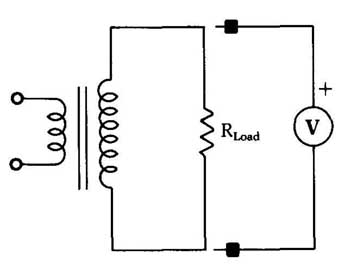
_ Fig. 9 This is the test hook-up for checking the turns ratio of a transformer.
Rewinding transformers:
Usually, when a transformer tests bad, you will be inclined to simply discard it and replace it with a new transformer of the same specifications. Unfortunately, it’s sometimes difficult to find an exact replacement for a specific transformer. Occasion ally, you will run into a problem with physical size. The available replacement transformer might have the same electrical specifications as the original unit, but if it has a larger body, it might not fit into the available space in the equipment being serviced.
Even if you do find a suitable replacement transformer, these devices are generally rather expensive. In some cases, it might make good economic sense to try to repair the defective original transformer by rewinding it, rather than simply replacing it. An other reason you might need to rewind a transformer is if you can’t find one with quite the required turns ratio. By rewinding the secondary, you can redesign the transformer’s specifications to suit your requirements. To aid you in such repairs, this section will discuss the procedure for rewinding a transformer.
Note that rewinding a transformer is a very picky, time- consuming job. It takes a lot of patience, good concentration, and a steady hand. Many electronics technicians simply aren’t temperamentally suited for such work. For them it would always be worth the extra expense to seek out and purchase a replacement transformer of the required type. Before attempting such a repair to save on the cost of a new transformer, you should also consider what your time is worth.
We will only cover the procedure for rewinding the secondary winding of a transformer. It’s possible to rewind a trans former’s primary winding, but this procedure is almost always more trouble than it’s worth.
Try to avoid attempting such repairs on transformers with multiple secondary windings. The design of the specific transformer in question also will help determine the suitability of such a repair attempt. In some transformers, the secondary winding is on top of the primary winding. Such transformers are usually re-windable. Other transformers, however, have the primary winding on top of the secondary winding. This arrangement is more common in step-up transformers than in step-down transformers. Repairing this type of device would be excessively difficult and time-consuming. It probably would not be worthwhile.
When attempting to rewind a transformer, it’s vital to work slowly, carefully, and gently. Never use force.
If you intend to change the turns ratio, you must use a transformer with the correct core size. The more power passing through the transformer, the larger the core must be. A chart for roughly determining the cross-sectional area of a transformer core is given in Table 6-1. Of course, if you are reducing the secondary voltage, there should be no problem. These cores sizes are the minimum for each wattage level.
Electrically, it doesn’t matter if the transformer’s core is too big, although the device will be physically bulkier than it needs to be. The key point is that you cannot reasonably expect to make too large a change in the original transformer’s output power. For example, if the transformer was originally rated for 24.6 V at 1.5 amps, you should be able to rewind it for 30 Vat 1 amp, or 18 V at 1.75 amps, but not 35 Vat 3 amps. The core would be too small, and the transformer would burn itself out and possibly damage other components in the circuit. It also might be a fire hazard.
__Table 1 The cross-sectional area of a transformer’s core limits its power-handling capability.
Cross-sectional area in square inches | Maximum power in watts
1.00 --> 45
1.25 --> 50
1.50 --> 65
1.75 --> 75
2.00 --> 120
2.25 --> 150
2.75 --> 230
3.00 --> 275
3.25 --> 330
3.75 --> 440
4.00 --> 520
To begin the rewinding process, you must first open up the transformer. Remove all screws or anything else holding the transformer together. The body of the transformer (the core) is made up of multiple sheets of laminated metal. During manufacture, these laminations were soaked in a special enamel and then baked, so they are tightly sealed to one another. The enamel protects the transformer from environmental contamination and helps prevent annoying transformer buzz. Unfortunately, it also makes it difficult to remove the laminations.
You must individually break the coat of enamel holding each lamination in place. Be very careful when doing so. If you use too much force, your tool could slip and damage the transformer’s wires. Too much damage to the wrong wires could render the transformer unrepairable.
You are likely to damage a few of the laminations themselves, especially the first few, which are almost always the hardest to remove. They have the most enamel, since they are on the out side. If you ruin a few laminations, don’t worry too much about it. Because you will be reassembling the transformer by hand, all the original laminations won’t fit back into place anyway. Just try to work as carefully as possible and not damage too many of the laminations.
The best way to remove the first few laminations is to use a small screwdriver. Attempt to work the blade between the top most lamination and the next one. A few gentle taps with a hammer can help push the screwdriver’s blade between the laminations. Don’t use hard blows. Be aware that this process is likely to damage the blade of the screwdriver, so don’t use an expensive, precision tool. A small, cheap screwdriver is not hard to find and will do the job. The blade should be as narrow as possible.
Work the blade gently back and forth between the laminations until you manage to break them apart. This procedure is difficult until you get the hang of it.
After you have removed a few laminations, you will almost certainly come across some that are I shaped. An I-shaped lamination will do a better job than the screwdriver, so make the switch as soon as you can.
After removing the laminations, you can unwind the secondary of the transformer. Do so slowly and carefully, at a time and place where you are unlikely to be disturbed in the middle of the job. Be careful not to break or tangle the wire, especially if you in tend to reuse it in the new winding. Keep track of the number of turns in the secondary winding. To rewind the transformer for the original specifications, you will need to use exactly the same number of turns. If you intend to change the turns ratio, you will still need to know how many turns there were so you can perform the necessary conversion.
If you are repairing a transformer with shorted windings, you should not attempt to reuse the original wire in the new secondary winding. Use enameled wire of the exact gauge as the original. You also will need to use new wire if the new secondary winding calls for more turns than were used in the original transformer.
To determine the number of turns required for a different secondary voltage, determine the original number of turns per volt. Just divide the total number of turns in the original secondary winding by the original output voltage:
TV = To / Eo
where TV is the number of turns per volt, To is the total number of turns in the original winding, and E is the original secondary volt age. As an example, let’s say you have a 24.6 V transformer with 125 turns in its original secondary winding. The turns per volt for this transformer is:
TV=125/24.6
= 5.0813
Now, if you want to rewind this transformer for a new secondary voltage of 18 V, just multiply the desired voltage by the turns-per-volt value:
NT = En X TV
= 18 X 5.0813
= 91.4634
where NT is the number of turns required for the new secondary winding, En is the desired output voltage, and TV, of course, is the turns-per-volt value derived previously.
Don’t worry too much about the fractional turns. In this ex ample, 91.5 turns would certainly be close enough. Actually the difference between 90 or 91 turns and 92 or 93 turns will be negligible. Make the new winding as close as possible to the calculated number of turns, but don’t be obsessive about it.
The current-handling capability depends on the wire’s cross-sectional area. To use the transformer for more than its originally rated current-handling capability, you might need to use a heavier gauge wire. I don’t really recommend doing so.
Inmost cases, you should use new enameled wire for the new secondary winding. The original wire might have physical strain and kinks as a result of being tightly wound so long, then being unwound and rewound. There also might be chips in its insulating enamel, which could eventually result in shorted turns. If you were very careful in unwinding the original coil, however, you might be able to reuse the original wire, if you wish. Don’t reuse the original wire if you are repairing a defective transformer, especially one with shorted turns. You’ll just be rebuilding a defective transformer.
Wrap the wire around the core as closely as you can. Don’t leave any space between turns so you get the maximum number of turns in the minimum amount of space. We guarantee you won’t be able to get the windings as tight as they were in the original manufactured unit, so your rebuilt transformer is likely to be a little bulkier. This is okay.
When you finish one layer of turns, put some kind of insulation over it before you begin the next, overlapping layer. You can use wax paper, electrician’s tape, or any other thin, insulating material, provided that it’s capable of withstanding the maxi mum voltage of the winding. Apply this insulating material as tightly and as wrinkle- and bubble-free as possible to prevent excessive bulk.
Once you have completely wound the new secondary, you must reassemble the transformer’s laminations. Some will be E shaped; others will be I shaped. They fit together as illustrated in Fig. 10. Because you are working by hand, and the trans former was originally machine-assembled, it is-almost a sure bet that you’ll end up with a few laminations left over—typically about two to four of each type (E and!) if you are good at such delicate work. If you can’t fit these extra laminations back into the transformer’s core, just discard them and don’t worry about it. These omitted laminations will lower the power rating of the transformer slightly, but the difference is not likely to be significant or even noticeable. Of course, if you end up with a dozen or more laminations left that won’t fit back into the core, you better de-rate the power-handling capability of the rebuilt transformer somewhat.
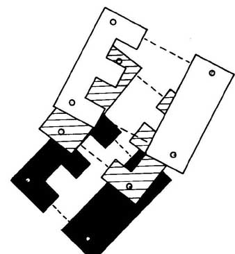
_ Fig. 10 The laminations of a transformer’s core fit together like a simple
puzzle.
Finally, replace all the original screws and other hold-down devices that you removed from the original transformer.
==Testing integrated circuits, modules, and PC units==
Printed-circuit units are appearing in radios and TV sets in large numbers. These devices range from a simple RC integrator used in vertical sync circuits to the equivalent of a whole amplifier circuit, each in one sealed package. Admittedly, these units are impossible to check in detail because you can’t get into them to test individual parts. However, there is at least one reliable check you can do: an output check.
In the integrated circuit, check to see that the proper composite sync signal is present at the input. If it’s not found at the out put, the unit is probably bad. This method can be used on any module. Three things must be carefully checked before any printed-circuit unit is condemned: the supply voltages and cur rents; the input signal; and the output signal.
For instance, if the modular circuit is an audio amplifier, it will need a certain amount of dc voltage supply and draw a certain amount of current. With 0.5 V of audio signal on the input, it has a normal output of 5 V. If the unit meets these specifications, look elsewhere for the trouble. Don’t replace units at random. Make definite tests and be positive before you replace any units.
The scope and signal generator can tell you if a stage is definitely bad by checking input vs. output. If it’s bad, don’t overlook the supply voltage.
==A quick check for microphones==
There’s a good, quick check for almost all microphones, especially the common dynamic and crystal types: Make them talk, rather than listen. Any microphone can reproduce sound, as well as pick it up. For instance, if you have a tape recorder that won’t record, the first question is whether the trouble is in the mike or the amplifier. Feed an audio signal into the mike and listen.
You can use an audio-signal generator or any audio signal from a radio or TV set. It takes only a very small signal to make a mike talk. A dynamic microphone is nothing but a specially built dynamic speaker. Crystal mikes won’t talk as loudly as dynamics, but even the variable-reluctance types used in communications work will talk.
Incidentally, this is a good quality check for microphones if the complaint is distortion in the sound output of a PA system or transmitter. By feeding a music or voice signal into the mike and listening to it, you can detect dragging voice coils, buzzes, etc. — defects that would distort the sound pickup. Also, if you happen to have a replacement cartridge for the type of mike you are testing, you can easily make A-B comparison tests of the sound quality of each.
This test can be reversed, too. If you have a complaint of possible mike trouble, hook up a small dynamic speaker to the mike input and talk into it. If the mike input is high impedance, use an output transformer to bring the low voice-coil impedance up enough to work. Actual high-impedance mike transformers will be up around 50,000 1 but you can use almost any output trans former. One of the old 25,000 transformers is good, but the test will work with even a 10,000 1 type.
If you’re checking for possible mike distortion, hold the mike at least 10 to 12 inches away as you talk. You’ll be surprised at the quality of the sound. Transistor radio speakers make good test mikes because of their tiny size.
==Checking phono cartridges with the scope==
When you have low gain in record-playing systems, one of the first things to determine is whether the trouble is in the cartridge or amplifier. The scope is a quick check for the cartridge. With its high-gain vertical amplifier, you can use it as a sensitive ac volt meter.
Put a single-tone test record on the turntable, disconnect the cartridge leads at the amplifier (although this isn’t really necessary if they’re soldered in), and hook the vertical input of the scope to the hot wire, as shown in Fig. 11. Set the vertical gain control of the oscilloscope to give about 1 inch deflection for a 1 V p-p input. Put the stylus on a band of continuous tone — say 400 Hz. For the average crystal cartridge, the output will be from 1 to 3V.
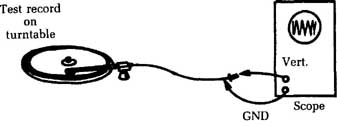
_ Fig. 11 An oscilloscope can be used to check a phono cartridge. Test record
on turntable; GND; Scope
If you want to make a frequency run on the cartridge, you can do it even with a narrow-band scope. Most of these scopes will go up to at least 50 kHz without trouble. You’ll need a test record with a band of all frequencies on it, starting at 30 Hz and going to 20 to 30 kHz, at the same output level. Several test records of this type are available. You also can use this test on the whole amplifier.
One valuable application of a scope test is checking stereo cartridges for equality of output in the two channels. Use a test record with a monaural band at about 400 Hz or a stereo band with equal outputs in the two channels. Several test records have this band for checking speaker phasing, channel balance, etc. Just read the output from each side of the cartridge; the two should be the same.
Cartridge tests also can be made with an ac VTVM. The readings will be the same as with the scope: 1 to 3 V p-p. Even an AC- VOLTS scale on the VOM will do, although the meter must have a sensitivity of at least 10,000 per volt on ac. The low input impedance of the VOM reduces the readings. They average from 0.3 to 0.4 V, where the scope reads 1 to 3V. Crystal and ceramic phono cartridges should work into a load impedance of 3 to 4 M.
==Impedance checker for speakers==
Impedance, or ac resistance, is generally difficult to measure. It’s nowhere near as straightforward as dc resistance. For dc resistance, 100 is 100 , and that’s that. It doesn’t matter what signal is flowing through the resistive component. Impedance, on the other hand, is frequency-dependent. A component that has a 100 impedance for a signal of 200 Hz might have an impedance of 38 when the signal frequency is changed to 500 HZ.
For speakers, the situation is further complicated because the intended signal is a complex combination of multiple- frequency components. To make some sort of comparison possible, a standard test signal of 1 kHz (1,000 ohms) is assumed in de fining the impedance of a speaker. The test signal is a pure sine wave, to avoid confusion from harmonic-frequency components.
The circuit shown in Fig. 12 is designed to test speaker impedance by comparing the speaker being tested with a known 8 ohm speaker. A suitable parts list for this project is given in Table 2.
IC1 and its associated components (R1 through R5 and C1 through C3) form a simple sine wave oscillator. The component values suggested in the parts list will give a signal frequency very close to 1 kHz.
Fortunately for this type of testing, high precision in the signal frequency isn’t required. This simple circuit’s frequency will be close enough for our purposes. If you prefer, you can replace this sine wave oscillator circuit with almost any other sine wave oscillator. The nominal signal frequency should be 1,000 Hz, and the signal amplitude should be between 3 and 10 V.
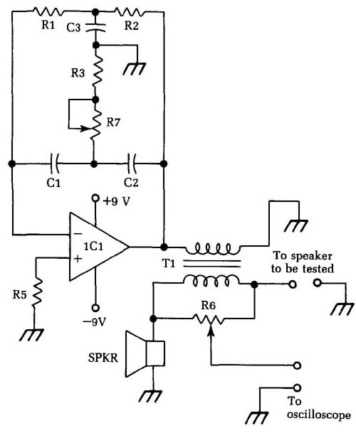
Fig. 12 This circuit can be used to test the impedance of loudspeakers.
Table 2 The parts list for the speaker impedance checker circuit of Fig. 12.
IC1 741 op amp
C1, C2 0.01 uF capacitor
C3 0.022 uF capacitor
R1, R2, R5 15K 1/2 Watt 10% resistor
R3 3.3K 1/2 Watt 10% resistor
R4 10-K trimpot
R6 1 K potentiometer
T1 audio impedance matching transformer primary 1K; secondary = 8 ohms
S1 -- small 8 ohm speaker
When you first set up this circuit, you must calibrate the oscillator circuit. Simply adjust trimpot R4 until you hear the clearest, purest tone from the speaker. If you are a perfectionist, you can use an oscilloscope to monitor the output of IC1. Again, adjust trimpot R4 until the oscilloscope shows the most distortion-free sine wave.
This is a set-and-forget type of control. It might be a good idea to use a drop of nail polish, glue, or paint to hold the trimpot’s shaft in place once you have calibrated it to prevent the need for frequent recalibration. This is a particularly good idea if you will move the tester around a lot.
The sine wave signal is fed through an impedance-matching transformer (Ti) to give it a nominal impedance of 8 ohm. The impedance of the speaker under test (connected to the circuit’s test terminals) is compared to the impedance of the reference speaker (8 ohm). The two speakers to be compared are in a bridge configuration, along with the two halves of potentiometer R6. This portion of the circuit is redrawn as an equivalent circuit to give you a clearer picture of the bridge. When the two halves of the bridge have an equal resistance (or impedance), the oscilloscope will show a deep null.
You can easily make a calibrated dial for this tester by attaching known small-valued resistors across the test terminals and marking the dial for the null point. For example, you might start out with an 8 resistor. While watching the oscilloscope, slowly adjust potentiometer R1 for the deepest null. Mark the potentiometer’s position “8” on the dial. Repeat this procedure for resistances to match each of the standard speaker impedances: 3.2 , 4 –ohm, 8–ohm, 16 , 32 , 40 , and 100-ohm.
Now, when you connect an unknown speaker across the circuit’s test terminals, you can adjust potentiometer R6 until you get the deepest possible null as indicated by the oscilloscope. Read off the approximate value from your calibrated dial. Some times you will get a speaker that falls between two standard calibration points. That’s o.k. Just interpolate the value, or round it off to the nearest standard impedance value.
If you don’t have an oscilloscope handy, you can substitute a pair of headphones and listen carefully for the maximum audible null. This method is a little less precise and requires more concentration. You also will have to make an effort not to be distracted by the tones being produced directly by the two speakers.
==Testing diodes==
You can test a semiconductor diode with an ohmmeter, but you must be careful. Some semiconductor diodes are designed to handle only very small voltages. Too high a test voltage could damage or destroy the diode you are attempting to test.
To be safe, use an ohmmeter that uses a battery voltage of no more than 1.5 V. Some multimeters use up to a 9 V battery to power the ohmmeter section. It’s a good idea to test unknown diodes on the highest range of your ohmmeter because, at these higher ranges, the ohmmeter has greater internal resistance, limits the current more, and puts less voltage across the diode connected to the test leads. We’ve found that, for most common semiconductor diodes, the upper resistance ranges give the easiest to read results anyway.
Measure the resistance across the diode from anode to cathode. Connect the ohmmeter’s positive lead to the anode, and the negative lead to the cathode. This arrangement forward-biases the diode. You should get a very low resistance reading. The exact value will depend on the specific type of diode being tested. Some diodes have a forward-bias resistance of about 1 to 10 1. Others might have forward-bias resistances of just a few tenths of an ohm. A few diodes might have higher forward-bias resistance.
Now, reverse the test leads. Connect the positive lead to the diode’s cathode, and the negative lead to the anode. Now you should get a very high resistance reading because the diode is re verse-biased. On some diodes, the reverse bias might be just a couple hundred ohms, while others will exhibit resistances well into the megohm (millions of ohms) range. Most semiconductor diodes will have a reverse-bias range of at least several k-ohms.
It’s usually relatively easy to tell the anode from the cathode on a semiconductor diode. Often a stripe around one end of the component’s body will indicate the anode, as illustrated in Fig. 13. Some diodes have a tapered body at the anode end, as shown in Fig. 14. Even if there is no visual indication at all, however, this test procedure will indicate which is which, assuming the diode is good.
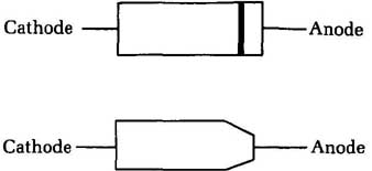
(top) Fig. 13 On some diodes, the anode is indicated by a slope. Cathode, Anode
(tabove) Fig. 14 On some diodes, the body is tapered on one end to indicate
the location of the anode. Cathode, Anode
For quick, general-purpose go/no go diode testing, you just want to make sure the diode exhibits a low resistance in one direction (when it’s forward biased) and a significantly higher resistance when the applied test voltage has its polarity reversed (the diode is reverse biased). If you get a low resistance in both directions, the diode is shorted and should be replaced. If you get a high resistance in both directions, the diode is open and should be replaced. For the most part, a semiconductor diode is either good or bad. When it goes bad, it’s almost always shorted or open, so this test is sufficient.
In some cases, you might be concerned with the exact specifications of the diode. The most important factor is the front-to-back ratio of the diode, a ratio of the forward-biased resistance to the reverse-biased resistance:
FBR= Rf/ Rr
where FBR is the front-to-back ratio, Rf is the resistance when the diode is forward-biased, and Rr is the resistance when the diode is reverse-biased.
For example, if the forward-bias resistance is 75 ohm, and the reverse-bias resistance is 12,500 (12.5K), the front-to-back ratio is equal to:
FBR = = 156.667
Is this reading good or bad? That depends entirely on the in tended specifications for the diode in question. You must com pare your test results with the manufacturer’s specification sheet for that type number, or you can make direct comparisons with a diode of the same type that is known to be good. This example is probably a good diode. Usually if there are problems, they will result in lower front-to-back ratios.
==Replacing transistors==
It’s often difficult to find an exact brand-name replacement for a bad transistor, especially one from an older, discontinued set. Foreign-manufactured equipment tends to include a lot of unusually numbered parts.
Many component manufacturers offer a line of general re placement devices, and all good technicians should have as many cross-reference guides as they can find. Unfortunately, it’s not a good idea to place too much faith in any cross-reference guide. The recommended replacements are always just close approximations, not exact duplicates. A guide might list transistor A as a replacement for transistor B, and it will probably work great in 99 percent of the circuits using transistor B. But you may have the exceptional circuit. Also, don’t assume that the replacements can work in either direction. That is, just because A is listed as a re placement for B, don’t assume you could use B as a replacement for A.
The best cross-reference guides are ones that include data and specifications for each device. Generally, you will be most concerned with the voltage and current ratings and the cutoff frequency. The other specs are also important, of course, but in most applications they offer more room for error. When in doubt, or if you run into problems, use a replacement transistor with slightly higher ratings than the unit you are replacing.
==Derating components==
A component circuit designer should take the power-handling capabilities of each component of the circuit into account. If the original component is rated for 250 V, don’t replace it with one rated for only 100 V. Even if the circuit works correctly with the substitution, the underrated replacement component will be subject to premature failure. You’ll just need to replace it again soon.
In some cases, the component originally installed by the manufacturer might be significantly overrated because of parts availability or some other reason. For example, we have seen ceramic disc capacitors rated for working voltages of 500 V in pocket radios that operate off of a standard 9 V battery. It’s highly unlikely that the component will ever see any voltage coming even remotely close to 500 V in this circuit. In this case, you can safely substitute a capacitor with a lower voltage rating.
Usually things aren’t quite so obvious. The general rule of thumb is to never substitute a component with a lower voltage or power rating than the original component unless you are absolutely sure that the manufacturer overrated the component for an electrically irrelevant reason (such as parts availability or cost). If there is any doubt, don’t make the substitution. You might just be asking for trouble in the future.
On the other hand, you usually can overrate the voltage or power ratings of your replacement components. For example, you can replace a 2.2K, 1/4 W resistor with a 2.2K, ½ W resistor. All you will have to worry about is whether or not the new, heftier component will physically fit.
In some cases, a manufacturer might have cut corners or the circuit designer might have erred, and the original component might not be adequately rated, or just barely so. If you service a number of units of a given piece of electronic equipment and repeatedly come up against a specific capacitor being burnt out, the odds are that its working voltage rating just isn’t good enough for the operation of the equipment. In this case, you definitely don’t want to use an exact replacement. Substitute a capacitor with the same capacitance value, but with a somewhat higher working voltage rating. This replacement will often give the equipment much greater reliability. We’re constantly shocked by how often manufacturers use inadequately rated components, even in high-grade equipment.
As a rough rule of thumb, never expose any component to more than 75 to 80 percent of its maximum voltage or power rating during the normal operation of the circuit. For example, never expect a capacitor rated for 250 V to handle more than about 188 to 200 V, and a 0.25 W resistor shouldn’t have to carry more than about 0.2 W in the normal operation of the circuit. This rule will leave some headroom for the component to handle any unexpected transients or overvoltage conditions without unnecessary damage.
<< -- -->>