AMAZON multi-meters discounts AMAZON oscilloscope discounts
An electromagnetic pulse is a transient electromagnetic signal produced by a nuclear explosion in or above the Earth's atmosphere. Though not considered (directly) dangerous to people, the electromagnetic pulse (EMP) is a potential threat to many electronic signals.
In a typical nuclear detonation, parts of the shell casing and other materials are rapidly reduced to a very hot, compressed gas, which upon expansion gives rise to enormous amounts of mechanical and thermal energy. At the same time the nuclear reactions release a tremendous amount of energy as initial nuclear radiation (INR). This INR is in the form of rapidly-moving neutrons and high-energy electromagnetic radiation, called x-rays and prompt gamma rays. Roughly a minute after detonation, the radioactive decay of the fission products gives rise to additional gamma rays and electrons (or beta particles), known as residual nuclear radiation (RNR). The distribution of the total explosive energy of a hypothetical fission detonation in the atmosphere below an altitude of 6 miles (10 km) is 50% blast (mechanical), 35% thermal, 10% RNR, 5% INR. At higher altitudes where the air is less dense, the thermal energy increases and the blast (mechanical) energy decreases proportionally.
EMP is associated with the INR output, which is a small percentage of the total explosive energy. Nevertheless, EMP is still capable of transferring something of the order of 0.1 - 0.9 joule/m2 (0.007 - 0.06 ft-lbf/ft2) onto a collector, more than enough to cause upset or damage to normal semiconductor devices.
As prompt gamma rays move away from a high-altitude nuclear detonation, those gamma rays moving toward the Earth penetrate a more-dense region of the atmosphere called the source or depletion region. In this 6-mile (10-km) region, approximately 15 - 21 miles (25 - 35 km) above the Earth, the highly-energetic gamma rays interact with the air molecules to form Compton electrons (with energies starting at 1 MeV) and less-energetic gamma rays, which then proceed in the same general direction as the original gamma rays. The fast Compton electrons eventually slow down by stripping other electrons from the air molecules to form secondary electron-ion pairs. (Though these secondary electrons and ions don't contribute to the generation of the EMP, they do cause the region to become highly conductive, and therefore play an important role in determining the EMP wave shape and amplitude.) While slowing down, the very-intense, short-duration flux of Compton electrons is also deflected by the Earth's geomagnetic field. The Compton electrons then spiral about the geomagnetic lines, radiating electromagnetic energy in the form of EMP until they eventually recombine with local, positively-charged ions
It's also possible for INR (both x-rays and gamma rays) to directly interact with systems, causing EMP signals internal to structures. This phenomenon has been called internal or system-generated EMP and is potentially a serious problem for satellites in orbit or for electronics in metallic enclosures on or near the ground. These forms of EMP are generated by x-rays interacting with satellites and gamma rays impinging on ground-based enclosures, producing currents of Compton electrons internally that then produce electromagnetic waves.
An estimate of about 1 joule (0.7 ft-lbf) of EMP-coupled energy is considered reasonable for many systems. Even if the coupling onto circuits is inefficient, as little as 10-13 J can upset some semiconductor devices and 10-6 J can cause damage. The potential for such upset and damage in critical electronic circuits has led to the incorporation of EMP protection in many system designs. The protection is most prevalent in communication systems whose disruption by EMP is considered an important civil and military vulnerability.
The most common form of protection incorporated in system designs is a combination of shielding and penetration control. The diagram below shows a protection scheme in which a system's electronics E is isolated from the external environment by one or more nested, shielded enclosures (often called Faraday cages). Penetration control is then maintained by minimizing the number of shield penetrations (in this case, a power line, a signal line, and a ground wire connecting E to earth ground G) and by applying terminal-protection devices, such as spark gaps, Zener diodes, or metal-oxide varistors, at selected shield-penetration points (A, A', A", B, B', and B"; or Z, Z', and Z"; or both). In this way, system protection can be designed not only for EMP but also for other electromagnetic transients (such as near-strike lightning and electromagnetic interference). Furthermore, cost-effective, field-maintainable protection can be achieved properly selecting off-the-shelf shielding techniques and terminal-protection devices and applying them to the systems.
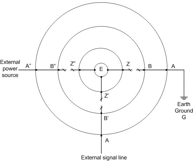
above: Typical system protection scheme. Click here or image to enlarge.