AMAZON multi-meters discounts AMAZON oscilloscope discounts
Any current-carrying cable or wire generates a magnetic field. The direction of this magnetic field for current flowing in a long straight wire can be understood using the right-hand rule. With the right-hand thumb pointed in the direction of the current flow (along the axis of the wire), the fingers will show the direction of magnetic field lines. It's not difficult to imagine the complex magnetic fields which exist near heavy electric machinery or where many cables are routed through common conduit or tray. Lenz's Law says that currents can be made to flow in conductors by moving them through a magnetic field. Similarly, a changing magnetic field will induce currents in a stationary conductor which is in the field. Since most wiring is fixed in place, varying currents are the usual cause of magnetic coupling.
The figure below shows a magnetically-coupled noise model analogous to the one presented earlier for capacitively-coupled noise. Looking at both models reveals that the primary means of noise coupling can be determined by changing the signal-source impedance, R signal. If R signal is reduced, capacitively-coupled noise will decrease while magnetically-coupled noise will increase.
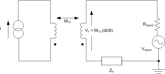
above: Magnetic coupling equivalent (noise-modeling)
circuit
Magnetic coupling is much more challenging to reduce than capacitive coupling because magnetic fields can penetrate conductive shields. Two types of loss -- reflection and absorption -- characterize how a shield works. Reflection loss is related to the ratio between the electromagnetic wave impedance and the shield impedance. Absorption loss is directly proportional to shield thickness and inversely proportional to shield material skin depth. It's highest at high frequencies and falls rapidly at low frequencies.
Fortunately, there are other ways to reduce magnetically-coupled interference other than shielding. The voltage induced in a single turn of wire by the magnetic field lines which cut the loop can be derived from Faraday's Law.
Making the general assumptions that the flux density (B) is sinusoidally time varying, as it would be for AC power line currents, and that B is constant over the area (A) of the loop, we obtain the following expression:
Vn = (jωBAcosθ) 10-8
Here, B is the value of the flux density in Gauss, A is the area of the loop cut by the magnetic field lines in cm2, and θ is the angle between the two (Figure below).
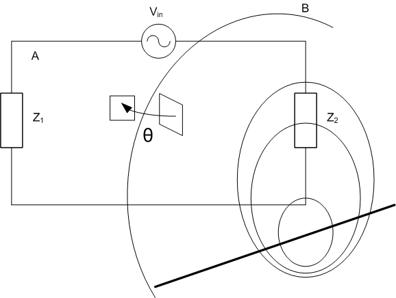
above: Induced Noise and Loop Area
These three parameters are all under the control of the system engineer. The magnetic field can be reduced by separating the source of the field from the receiving loop or by twisting the source wires. Loop area can be reduced by routing the conductors which form the loop closer together or by reducing the length of the conductors.