AMAZON multi-meters discounts AMAZON oscilloscope discounts
There are many types of signal generators in common use. The most familiar instrument is the amplitude-modulated ( AM) generator which has a multitude of applications, such as alignment of radio receivers, stage-gain measurements, resonant-frequency determination, calibration of auxiliary equipment, signal-substitution tests in troubleshooting procedures, and measuring the Q of tuned circuits. Marker generators are a somewhat more elaborate type of signal genera tor, and almost everyone has at least a basic understanding of their operation. The chief distinction between a marker generator and an ordinary AM generator is that a marker generator has an output of up to 250 mHz, plus calibrating facilities.
Quartz-crystal oscillators are commonly built into marker generators; this feature permits frequencies to be set to considerably higher accuracy than is possible with an ordinary AM generator.
The AM and marker generators are comparatively simple instruments which provide known frequencies within rated accuracy limits ; however, they do not supply a known output voltage. The output voltage is adjustable over the necessary range, but no indication is provided concerning the number of microvolts or millivolts that are applied to the receiver or circuit under test. Hence, you cannot use an AM generator or a marker generator to measure the sensitivity of a receiver.
Sensitivity is defined as the number of microvolts that must be applied to a radio or TV receiver to obtain a standard output (usually 1 volt de from the second detector). Similarly, you cannot use an AM generator or a marker generator to calibrate a field-strength meter. The purpose of a field-strength meter is to indicate the number of microvolts that are applied to its in put terminals.
Oldsters will recall that almost any device that generated an r-f signal was called a signal generator in the early days of generators. Even today, instruments such as grid-dip oscillators are sometimes considered as signal generators. But as the state of the art developed, the standards for test-signal sources became higher. Many of us will recall that during World War II technicians at military bases gained valuable experience with precise signal sources. Military technicians were required to align receivers so that the tuning dials accurately indicated the incoming frequency. The receivers had to be carefully serviced to provide rated sensitivity. Moreover, it was the responsibility of the technician to check out selectivity, AVC characteristics, and image rejection.
Mobile radio technicians have much the same responsibility.
Mobile receivers are not fully useful unless they have a sensitivity of 1 microvolt or better. Selectivity must be optimized to pass an FM signal without objectionable distortion, and also to reject adjacent signals. Four known accurate frequencies are necessary to align a triple-conversion superheterodyne. Only a high-quality signal generator suffices for front-end alignment.
Evidently a suitable generator must provide both FM and AM carrier modulation. Hence, a generator that is quite satisfactory for application in one service area may be utterly use less in another application area.
Technicians employed in radar activity require signal generators which supply unusually high frequencies and also pro vide pulse modulation of the carrier. Receiver noise measurements are vital, and hence the inherent noise level of the generator must be minimized. By way of comparison, the inherent noise level of a TV marker generator might be quite high, but this would be of no concern-the signal levels utilized in the alignment of TV receivers are higher than those signals employed in alignment of radar receivers or communications equipment.
Communications equipment is multiplexed in some cases.
Signal generators used in maintenance and troubleshooting of multiplex receivers must provide comparatively elaborate carrier modulation. Various forms of pulse-amplitude modulation are most common, although specialized types of frequency modulation are also encountered. Single-sideband output may be required from a signal generator in testing other types of receiving systems. In any case, your selection of a signal generator must be made on the basis of its intended application.
Technically, a basic signal generator is a source of sine wave voltage of known frequency and amplitude. The frequency might be chosen between 10 kHz and 10,000 mHz. The amplitude is usually measured in microvolts, although some signal generators supply an output of several volts. On the other hand, a test oscillator is commonly defined as a source of sine-wave voltage that has a known accurate frequency, but an amplitude which is not known. However, test oscillators are often loosely termed signal generators. In an attempt to avoid confusion between the two basic types of instruments, complete and highly accurate generators have become known as standard-signal generators. Test oscillators should therefore never be referred to as standard-signal generators.
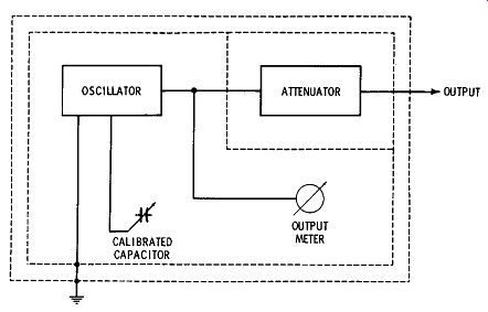
Fig. 1. Plan of a typical signal generator.
SIGNAL-GENERATOR FEATURES
The plan of a typical signal generator is depicted in Fig. 1. It comprises a sine-wave oscillator, a calibrated tuning capacitor, an output meter calibrated in microvolts, a precision attenuator, and a shielding system to prevent objectionable leakage of high-frequency energy into surrounding space.
True signal generators provide a good sine-wave output and they also minimize harmonics to the lowest percentage possible. On the other hand, test oscillators often have a highly distorted sine-wave output. The distortion components consist of even and odd harmonics. Higher frequency bands of a test oscillator often use the same output as on lower frequency bands-the high-frequency bands are merely calibrated in terms of harmonic frequencies.
Oscillators used in conventional generators are tunable over various bands of frequencies. It is not practical to design LC oscillators that provide a band-tuning range greater than about 3 to 1. Hence, band switching is required to select different coils for each band (Fig. 13). Oscillator circuits are designed to generate as pure a sine wave as possible. The out put amplitude on each band is also maintained as uniform as possible to minimize resetting of the level control for the out put meter. Some generators employ a form of AGC control to achieve maximum uniformity of output.
Oscillators with output frequencies up to 250 mHz generally utilize a carefully designed version of the Hartley or Colpitts circuits (Fig. 2). Frequency stability is an important consideration, inasmuch as it determines the accuracy rating of the generator, with respect to frequency. Stability is dependent on the effect of temperature, with respect to the resonant frequency. Warmup drift is unavoidable, but a well-designed generator quickly achieves its equilibrium condition and remains reasonably free from frequency drift with changes in ambient temperature. Temperature-compensating capacitors are often used in the oscillator circuitry for this reason.
Since the interelectrode capacitances of vacuum tubes differ, circuit configurations are used that make the oscillating frequency primarily dependent on the value of tuning capacitance only. This feature is also desirable because the interelectrode capacitances of a tube tend to change somewhat with age. A good sine-wave output requires that the resonant circuit have a high Q, and that the oscillator be lightly loaded.
Since the frequency of an oscillator tends to change when the B + varies, they usually have regulated power supplies.
(A) Hartley. (B) Colpitts.
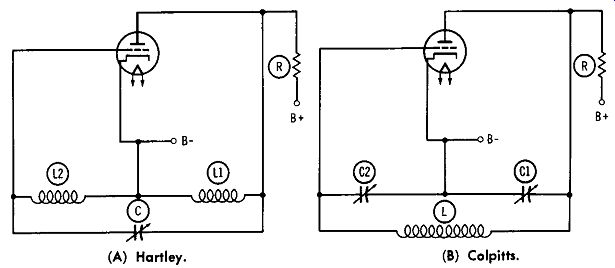
Fig. 2. Basic oscillator circuits.
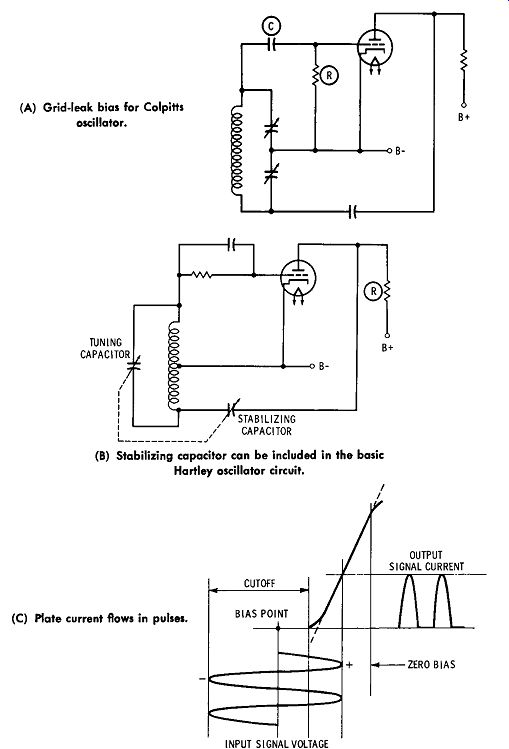
Fig. 3. Grid-leak bias arrangements. (A) Grid-leak bias for Colpitts oscillator.
(B) Stabilizing capacitor can be included in the basic Hartley oscillator
circuit. (C) Plate current flows in pulses.
Two general methods are used to make the oscillating frequency comparatively independent of tube interelectrode capacitances. The simplest method is to make the inductance fairly small and to use a large tuning capacitor. It follows from the basic circuitry shown in Fig. 2 that interelectrode capacitance then becomes a small percentage of the total tuning capacitance. In turn, the effect of tube aging or tube replacement on frequency stability is minimized. The other method is to tap down the tube connections to the coil so that the interelectrode capacitances are shunted across only a part of the inductance.
Frequency stability is also found to be dependent on the biasing arrangement used. No bias source is indicated in Fig. 2. An oscillator can be operated with cathode bias, fixed bias, or signal-developed bias. As previously noted, AGC bias may be employed. Signal-developed (grid-leak resistance) bias contributes basically to frequency stability. The grid-leak resistance is made as large as possible, while still permitting steady oscillation. Fig. 3A illustrates a typical configuration.
Signal-developed bias also assists in maintaining a reasonably uniform output amplitude over the tuning range. If the amplitude starts to rise, more bias is developed, which in turn, reduces the amplitude of oscillation to some extent.
Frequency stability can be improved in the Hartley con figuration by including a stabilizing capacitor, as depicted in Fig. 3B. This arrangement is called an impedance-stabilized oscillator. When the stabilizing capacitor has a certain critical value, the oscillating frequency remains practically unchanged over a wide range of plate-voltage variation. As the tank circuit is tuned to different frequencies, the stabilizing capacitance must also be varied ; hence, it is necessary to gang the two capacitors. This complication has caused the impedance-stabilized oscillator to find limited application, except in special-purpose generators for spot-frequency operation.
MODE OF OPERATION
Few oscillators in signal generators are operated in class A. One arrangement to be described later uses class-A operation. The cathode resistor biases the tube to its linear operating region. However, arrangements such as depicted in Fig. 3 employ grid-leak resistance bias which permits the tube to conduct only at the peak of oscillation. The plate current flows in pulses; hence the oscillator operates in class C. It might seem that lack of sine-wave plate-current flow would be conducive to harmonic generation. However, the oscillatory wave form has a practically pure sinusoidal shape, provided that the tank circuit has a high Q.
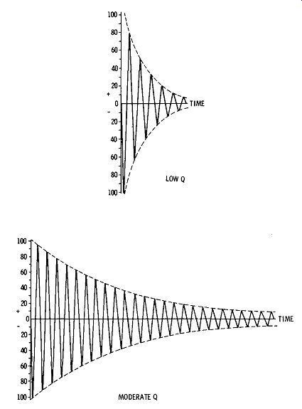
Fig. 4. The Q of the tank circuit determines the rate of decay of the sine
wave.
The efficiency of a class-C stage may be as high as 85%, compared with an efficiency of 25% for a class-A stage. Fig. 3C shows how grid-leak resistance bias places the operating point beyond cutoff. In turn, the plate current flows in pulses which are clipped tops of sine waves. However, if the Q of the tank is high, it produces a practically pure sine wave. The reason for this circuit action is the flywheel effect of the high Q tuned circuit. The tuned circuit is shock-excited once every cycle by the plate-current pulses. As depicted in Fig. 4, the rate of decay of a shock-excited sine wave depends on the Q of the circuit. Evidently, if the tuned circuit has a high Q, the sine-wave output decays very little from one cycle to the next.
We find that the Q of the tank circuit depends not only on the Q of the coil itself, but also on the amount of power which is drawn from the oscillator. If more power is drawn, the generated sine wave decays more from one cycle to the next (Fig. 4). Hence, the oscillator generates a purer sine wave, if it is lightly loaded. Frequency stability is also improved under light loading, because the tuned circuit is better isolated from conditions in the generator output system. Of course, some means of coupling must be provided between the oscillator and the output system.
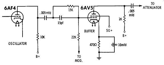
Fig. 5. A buffer stage minimizes the loading of the oscillator.
There are two principal coupling systems used to minimize loading of the oscillator. Fig. 5 depicts the use of a buffer stage. A power tube is generally preferred as a buffer, be cause it provides a comparatively large power output with very little grid-driving power. The buffer stage necessarily operates in class A because the sine-wave output from the oscillator must not be distorted. Hence, the 6A V5 in Fig. 5 is cathode-biased to its linear operating region. The efficiency of the buffer stage is low, but this is the price that is paid for good isolation of the oscillator section. A 6A V5 has a trans conductance of 5900 micromhos; hence, it is inherently cap able of considerable power amplification.
On the other hand, full advantage cannot be taken of the buffer's amplification potential, because the signal generator operates over a wide frequency range. In the arrangement of Fig. 5, the buffer must operate at frequencies up to approximately 10 mHz. Since reasonably uniform frequency response is desirable, a rather low value of plate resistance must be used. Note that the plate load is a 1K resistor. Furthermore, the output from the buffer is fed to the attenuator, which has a considerably lower resistance. In turn, the effective plate load resistance of the buffer is approximately 150 ohms.
The voltage gain is basically equal in the plate-load resistance multiplied by the transconductance of the 6A V5, or less than unity-about 0.9. However, the power gain is quite large.
In other words, the signal-output voltage is a bit less than the input grid-signal voltage, but the plate current is heavy while the grid current is nearly zero. The grid draws almost no power from the oscillator, but the plate supplies a much greater signal power. For example, suppose that the oscillator drives the buffer grid with 1 volt and an 0.3 milliampere.
This is driving power of 300 microwatts. On the other hand, the plate supplies (say) 0.9 volt across 150 ohms. This is a power of 5400 microwatts. Or stating it another way, the buffer stage has a power gain of 18.
Why does the grid draw any current at all in Fig. 5? It is because the grid has an input capacitance, plus the stray capacitance of its socket terminals. If the total input capacitance to the 6AV5 is 5 pf, the capacitive reactance of the grid input circuit is about 3000 ohms at 10 mc. Hence, the grid driving current is not zero, as might be supposed from simplified theory. Evidently, the buffer stage also has output capacitance, which must reduce the effective plate-load impedance at high frequencies. However, the plate-load resistance is quite low-approximately 150 ohms. Hence, the reduction in plate-load impedance is comparatively small. The output capacitance would have to be 100 pf before the capacitive reactance would be 150 ohms at 10 mHz.
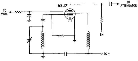
Fig. 6. Electron-coupled oscillator circuit.
Since the buffer tube is a beam-power tube, its control grid is electrostatically shielded from the plate. This simply means that changes in output capacitance are isolated from the control grid, and in turn, isolated from the oscillator. Accordingly, when the attenuator is switched, the associated changes in output capacitance do not affect the resonant frequency of the oscillator circuit. Of course, the shielding action of a screen grid is never 100% perfect. In turn, there is a very slight effect on oscillator frequency when the output capacitance is changed. In most cases, this residual lack of 100% isolation can be disregarded. On the other hand, if you are servicing mobile equipment, for example, you may require a generator which has more extensive buffering than depicted in Fig. 5.
The second type of coupling system commonly used in test oscillators and simple signal generators consists of an electron coupled oscillator configuration, as depicted in Fig. 6. Note that the screen grid, control grid, and cathode electrodes operate as a triode in the oscillator section. The electron stream rises and falls in amplitude at the oscillating frequency. A considerable portion of the electron stream passes through the screen grid and terminates at the plate. In turn, the out put signal is taken from the plate.
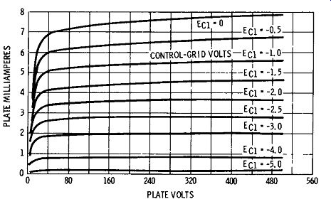
Fig. 7. Characteristics of a typical pentode.
Why does an electron-coupled configuration minimize loading on the oscillator? We know that the plate current of a pentode changes very slightly when the plate voltage changes.
Note in Fig. 7 that if you select a certain value of control grid voltage, the plate current changes little when you vary the plate voltage over a wide range. Furthermore, the screen grid in Fig. 6 operates as the anode (plate) in the oscillator section. The screen grid is shielded from the plate by the suppressor grid. In turn, capacitance variations in the plate-out put circuit are effectively decoupled from the screen grid. Hence, changing conditions in the plate-output circuit have little effect on the oscillating frequency.
The uniformity of output on each band can be improved by use of automatic control bias. A basic configuration is seen in Fig. 8. Diode M is back-biased from the cathode resistor.
However, when the amplitude of the sine-wave signal exceeds the back-bias value, diode M starts to conduct. The diode cur- rent flows to ground through R, and an increased negative bias is applied to the grid of the tube. In turn, the amplitude of oscillation is reduced. Amplified AGC is sometimes used in signal generators, just as in receivers. Amplified AGC pro vides better control action.
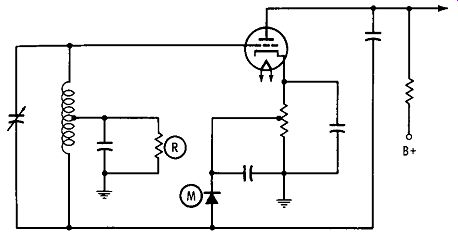
Fig. 8. Diode M develops a control bias which improves the uniformity of
the output amplitude.
AMPLITUDE MODULATION
Nearly all signal generators provide an amplitude-modulated output. Waveforms of unmodulated and modulated signals from an AM generator are depicted in Fig. 9. Most generators have a modulating frequency of 400 cycles; some have a modulating frequency of 1000 cycles. A few provide a vari able modulating frequency. Older generators often had a fixed percentage of modulation, such as 30%. However, the present trend is to provide a variable percentage of modulation. Many generators have a range from zero to 50% modulation; others provide up to 80% modulation. A few generators can supply a 100%-modulated output.
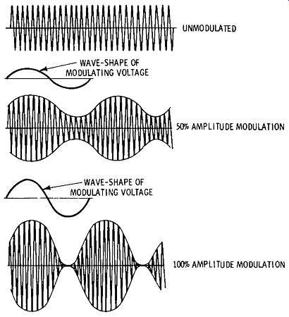
Fig. 9. Waveforms of unmodulated and modulated signals of an AM generator.
Sine-wave modulation is depicted in Fig. 9. This is the basic and usual modulation waveform. However, a few signal generators provide pulse modulation. For example, generators used to align radar receivers supply both sine-wave and pulse modulation. (See Fig. 10 for a representation of pulse modulation.) Older generators utilized internal modulation exclusively. Internal modulation means that the signal is modulated before it is applied to the attenuator. On the other hand, there is a strong trend to the use of external modulators. In this system, the modulator is not built into the generator, but it is a separate external unit. The output from the generator is modulated after it has passed through the attenuator.

Fig. 10. Pulse-modulated waveform of an AM generator.
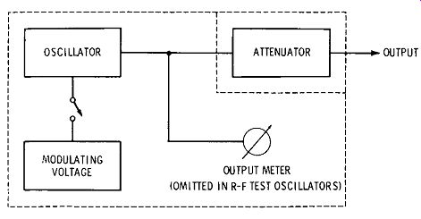
Fig. 11. In most signal generators the oscillator is directly modulated.
In the simplest signal generators the oscillator is modulated directly, as depicted in Fig. 11. For example, the plate volt age of the oscillator tube may be varied in accordance with the modulating signal shown in Fig. 9. Although this method is simple, it has some disadvantages. The chief disadvantage is incidental frequency modulation. We find that when the plate voltage on the oscillator is varied, the oscillating frequency, as well as the output amplitude, tends to change. This does really come as a surprise, because we know that regulated power supplies must be used to maintain oscillator frequency stability. What happens when the plate of the oscillator tube is modulated is this: the effective interelectrode capacitances of the tube are varied somewhat along with the variation in plate resistance. In turn, the oscillating frequency swings up and down slightly.
This incidental frequency modulation is not excessive, pro vided that rather small modulating percentages are used. On the other hand, high percentages of modulation cause a large amount of incidental frequency modulation. Various means are used to avoid this difficulty. For example, in the electron coupled arrangement of Fig. 9, the modulating voltage is applied to the suppressor grid. Again, in the buffer-stage arrangement of Fig. 5, the modulating voltage is applied to the control grid of the buffer tube. Note that the modulating voltage can be applied in series with diode M in Fig. 8 to minimize incidental frequency modulation.
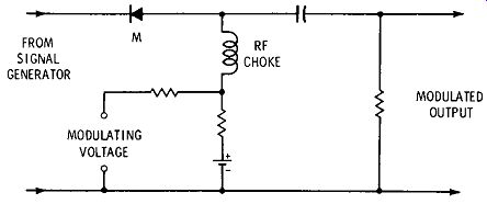
Fig. 12. Basic principle of an external modulator.
The basic principle of an external modulator is shown in Fig. 12. Diode M is biased to a suitable point on its forward characteristic. Since its characteristic is nonlinear, a change in bias is accompanied by more or less r-f current flow. The modulating voltage causes a change in bias voltage, and the out put signal is modulated accordingly. Incidental frequency modulation is avoided, because the complete generator-output system is between the oscillator and modulator. When a pulse modulating voltage is applied, 100% modulation can be obtained. On the other hand, sine-wave modulation is limited to 50% modulation or less, unless distortion of the modulation envelope can be tolerated.
ATTENUATORS

Fig. 13. Two potentiometers used as an attenuator.
All generators are provided with some type of attenuator.
Simple test oscillators often use a conventional potentiometer.
To reduce feedthrough voltage at the minimum setting, two potentiometers may be utilized, as shown in Fig. 13. On the other hand, an attenuator for a standard signal generator (Fig. 1) is designed to provide accurately-known output voltages over a typical range from 1 microvolt to 50,000 microvolts, or perhaps higher. The output meter is calibrated with a "set carrier" mark; when the carrier-level control is adjusted to bring the pointer to this reference level, the number of microvolts output is indicated by the attenuator setting.
Attenuators have a low impedance, such as 15 or 50 ohms.
There are two basic reasons for using low-impedance attenuator systems. First, stray capacitances have less serious effects in low-impedance circuits. A good attenuator system has an accuracy of ± 1% . This accuracy can be achieved only by minimizing the bypassing action of stray capacitances. For example, at 100 mc, 5 pf has a reactance of about 300 ohms.
Unless the attenuator resistance is in the order of 50 ohms or less, it is obviously impossible to achieve high accuracy. The second reason for employing a low-impedance attenuator is to minimize loading errors. For example, if the circuit under test has an input resistance of 500 ohms, the attenuator must evidently have a much lower output impedance, such as 50 ohms or less, to maintain reasonable accuracy of attenuator calibration.
The step attenuator is a ladder configuration, comprising 62-ohm and 56-ohm shunt resistors with 510-ohm series resistors. (Refer to Fig. 14.) When the fine attenuator is adjusted for full-scale indication on the meter, each step on the calibrated attenuator provides a known number of microvolts output. The output voltage is fed to a coaxial cable. It is impractical to use ordinary test leads, because the leads would radiate high-frequency energy. Moreover, standing waves can not be controlled on open test leads. The attenuator calibration would be meaningless unless a coaxial output cable were used. It is also essential to terminate the output cable with a resistor which has a value equal to characteristic impedance of the coax cable. The terminating resistor eliminates standing waves and makes the input impedance of the cable purely resistive (Fig. 15). Attenuators must be well shielded. A simple arrangement is depicted in Fig. 16. An important consideration in any shield design is make all high-frequency grounds at the same point in the shield structure. A single grounding point minimizes circulating r-f currents in the shield metal. Obviously, circulating ground currents cause radiation (leakage from the generator), and can cause feedthrough of high-frequency energy from in put to output of the attenuator system. Feedthrough not only impairs attenuator calibration, but it also increases the mini mum attainable signal level. Alignment of sensitive receivers may require that the attenuator reduce the available output to 1 microvolt.
Fig. 17 depicts the same basic ladder configuration as in Fig. 14, but with additional sections for greater attenuation and more elaborate shielding than shown in Fig. 16. Attenuator shielding is provided in addition to oscillator shielding as depicted in Fig. 14. In turn, both of these shield systems are supplemented by the generator case. The shielding provided in a standard signal generator is one of the basic features which distinguishes this type of instrument from a test oscillator. Without effective shielding, it is impossible to achieve accurate calibration of a step attenuator.
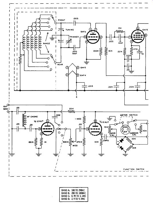
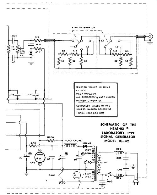
Fig. 14. Example of a step attenuator used in a signal generator. SCHEMATIC
OF THE HEATHKIT LABORATORY TYPE SIGNAL GENERATOR MODEL IG-42
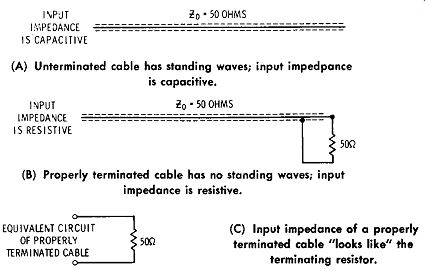
Fig. 15. Terminating resistor eliminates standing waves. (A) Unterminated
cable has standing waves; input impedance is capacitive. (B) Properly terminated
cable has no standing waves; input impedance is resistive.
GENERAL SHIELDING CONSIDERATIONS
Since the high-frequency sections of a signal generator must be both electrostatically and electromagnetically shielded, it might be supposed that ferrous shield material might be required. However, nonmagnetic metals such as copper serve as efficient electromagnetic shields at high frequencies. The reason for this is that the skin effect restricts the flow of high frequency currents to the surface of the shield. High-frequency energy cannot penetrate into the body of the copper.
Hence, a copper shield blocks the passage of high-frequency electromagnetic fields.
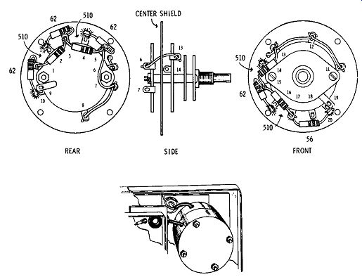
Fig. 16. Construction of a simple step attenuator.
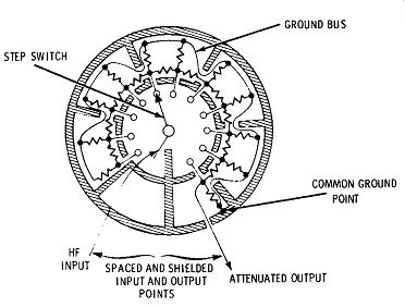
Fig. 17. A more elaborately shielded attenuator.
The shielding problem would be considerably simpler if each compartment could be made water-tight. Unfortunately, this is not possible in practice. Observe in Fig. 14 that input and output leads, as well as power-supply leads, must pass through the shield plates. The tuning-capacitor shaft as well as the switch shaft must be externally accessible. Moreover, tubes must eventually be replaced, and hence lids must be pro vided on associated shield compartments. In spite of these requirements, shield construction must be such that appreciable high-frequency leakage cannot occur.
High-frequency input and output leads consist of coaxial cable sections when the circuit impedance is comparatively low. Leads in high-impedance circuits must be exposed wires; however, double shielding may be utilized to minimize high frequency leakage. Thus, the oscillator coils are often enclosed in a separate coil-shield compartment. Power-supply leads are bypassed or decoupled before they emerge from the shield box. Note the 0.005-mfd bypass capacitors in Fig. 14. When a wide attenuation range is necessary, such capacitors are of the feedthrough types. Better shielding action is obtained if all of the bypassed leads are brought out near the same place on the shield box-this grouping minimizes circulating ground currents.
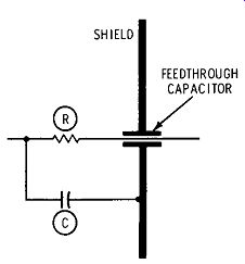
Fig. 18. RC low-pass filter supplements the feedthrough capacitor.
In some cases, the bypassing action of a feedthrough capacitor alone is insufficient. Accordingly, the feedthrough capacitor is supplemented by an RC or LC low-pass filter, as depicted in Fig. 18. An RC filter is suitable for use with B + supply leads. However, when heater leads must be filtered, an LC configuration is used. This is basically the same as the heater chokes and bypass capacitors used in i-f and r-f amplifiers of TV receivers. Access lids to compartments that contain tubes must make good contact all around to the shield box. Hence, various bolts or specially designed spring clips are commonly provided to insure good contact.
When double-shielding is utilized, such as for oscillator coils, the inner shield box is connected to the outer shield box at only one point. This single high-frequency ground point minimizes the flow of circulating ground currents. If a power-sup ply lead must be brought through the shields, it should enter near the common grounding point; leakage is minimized by filtering the lead at the walls of both compartments. The ex tent to which such measures are employed depends primarily on the minimum signal-output level which the generator must provide.
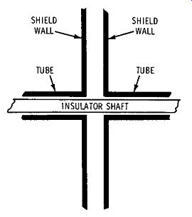
Fig. 19. Metallic tubes minimize high-frequency leakage.
Control shafts for tuning capacitors, switches, or potentiometers present another problem. Test oscillators may provide only a sliding spring contact against the shaft for high-frequency grounding. On the other hand, the residual leakage from this simple arrangement cannot be tolerated in calibrated signal generators. Two general methods are utilized to minimize leakage. In some cases, a metal control shaft is used. A specially designed collar is used where the shaft passes through the shield wall. The collar provides a very tight metal seal, while permitting shaft rotation. However, it is not always desirable to use a metal control shaft. If double-shielding is employed, it may not be practical to bring the shaft out near the common-grounding point. In such case, the shaft is very likely to set up circulating high-frequency ground currents.
This problem is overcome by using control shafts that are made of insulating material. Of course, a hole is present in the shield wall where the shaft passes through. To minimize high-frequency leakage via the entry, small metal tubes are provided, as depicted in Fig. 19. These tubes act as high frequency chokes, and they greatly attenuate high-frequency energy which attempts to flow through them. It is necessary that the choke tubes have a diameter which is considerably less than a half wavelength at the highest operating frequency of the generator. The length of the choke tubes is several times as great as their diameter.
UHF SIGNAL GENERATORS
The foregoing discussions and analyses concern basic features of generators that operate at frequencies below 250 mc.
At higher frequencies, oscillators cannot employ conventional coils and capacitors, attenuators cannot utilize resistive ladder networks. Radiation and high-frequency leakage must be controlled by additional means. As explained subsequently, lumpe DCircuit analysis must be supplanted by transmission line and waveguide analysis. Special tubes are used that have comparatively small interelectrode capacitances, low electrode inductance, and short transit time. At frequencies above 3000 mHz, conventional tube construction is unsuitable, and other types of tubes such as Klystrons are required.
TRANSISTORIZED SIGNAL GENERATORS
There is a trend today toward transistorized signal-genera tor circuitry. It can be anticipated that this will be a growing trend. Since a transistor is an amplifier, it can be made to supply its own input and operate as an oscillator. As seen in Fig. 20, a transistor can be compared with a vacuum tube the base is analogous to a control grid, the emitter to a cathode, and the collector to a plate. However, a transistor has low internal impedances (resistances) as compared with a tube. Hence, the base, or "grid," draws appreciable current. For this reason, it is often said that a transistor is a current-operated device.

Fig. 20. Comparison of transistor and vacuum tube. (A) Transistor is termed
a current-operated device because its impedances are low. (B) Pentode tube
is termed a voltage operated device because its impedances are high.
With the analogy to a vacuum tube in mind, it is easy to see how the sine-wave oscillator depicted in Fig. 21 works.
The output from the collector is fed back, via the tuned tank circuit, to the base. A sine wave necessarily appears across the high-Q tank circuit. When the coupling between primary and secondary is sufficiently tight, the amplified output from the collector more than makes up for the circuit losses. In turn, sustained sine-wave oscillation occurs. The purity of the waveform depends solely on the Q of the tank circuit. This Q value is determined by the r-f resistance of the tank coil, and also by the amount of r-f current that is taken from the output.
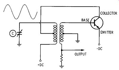
Fig. 21. A basic transistorized sine-wave oscillator.
As in a vacuum-tube type of signal generator, tuning capacitor C in Fig. 21 can provide a maximum frequency range of roughly 3-to-l. Hence, band switching must be employed to obtain a wide range of output frequencies. The configuration depicted in Fig. 21 is a "tickler" type of oscillator. Since it requires two coils, generator designers often prefer to use a single tapped coil in a Hartley circuit, as shown in Fig. 22.
This simplifies band-switching requirements, and reduces cost of manufacture. The tap point on a Hartley tank corresponds to the degree of coupling used in a tickler configuration.
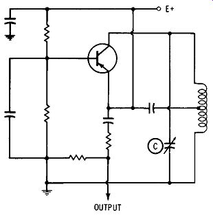
Fig. 22. Basic transistorized Hartley oscillator for a signal generator.
The similarity of the circuit in Fig. 22 to the circuit in Fig. 21 is evident. In both arrangements the DC supply volt age is applied to the emitter. This corresponds to the B + voltage applied to the plate of a vacuum tube. It makes no difference whether the supply voltage is applied to the plate or to the cathode of a vacuum tube, as long as the correct DC distribution is realized. Similarly, the supply voltage can be applied to the emitter of a transistor, as long as the correct DC distribution is maintained. The point of application is simply a matter of design convenience.
The r-f output is taken from the emitter circuit in both Fig. 21 and Fig. 22. Since the emitter has the lowest impedance (compared with the base and collector), load variations have least effect on the oscillating frequency. Just as in vacuum tube types of signal generators, it is very desirable to maintain the oscillating frequency constant in spite of output load variations. In some applications the output cable may be connected to a high-resistance load, but in other applications the output cable may be connected to a low-resistance load. If the generator is well designed, the oscillating frequency will remain practically unchanged.
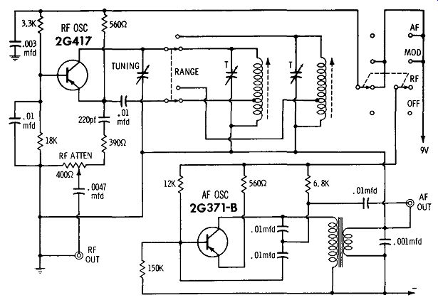
Fig. 23. Configuration of a transistorized signal generator.
Next, let us see how the transistorized Hartley oscillator is elaborated in a typical signal generator. Fig. 23 shows the circuitry that is used. Two bands are detailed in Fig. 23, al though the generator employs a total of seven bands. The seventh band is harmonically calibrated. Fundamental output is from 150 kHz to 166 mc. A transistorized 400-cycle audio oscillator is provided for amplitude modulation of the r-f signal.
A 400-ohm potentiometer serves as the r-f attenuator. Maximum r-f output is 50 millivolts rms. The percentage of modulation is fixed at approximately 30%. Note that the tank coils are provided with both trimmer capacitors and tuning slugs. This feature permits optimum tracking of the tuning dial. In other words, a given frequency of oscillation can be obtained by increasing the trimmer capacitance and turning the slug farther out of the tank coil.
Or, the trimmer capacitance can be reduced, and the slug turned farther into the coil. With the slug turned into the coil, the inductance is increased-the LC ratio is changed accordingly. This changes the frequency indication on the tuning dial. Hence, tracking can be optimized at the high and low ends of the tuning range.
The audio-oscillator circuit in Fig. 23 is somewhat novel in that it combines the features of both tickler-feedback (Fig. 21) and the Colpitts operation. In this case, the Colpitts arrangement generates a good sine wave, and tickler feedback provides a larger feedback voltage to obtain substantial out put. Observe how the r-f oscillator is modulated: The audio frequency output drops across the tickler coil, which is in series with the DC supply voltage to the r-f oscillator. When the audio oscillator is operating, its sine-wave output is super imposed on the DC voltage to the r-f oscillator. In turn, the r-f output is amplitude-modulated.
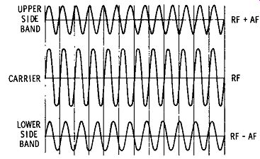
Fig. 24. Amplitude modulation generates a pair of sideband frequencies.
Note in passing that an r-f oscillator should not be amplitude-modulated when a signal generator is calibrated against a standard signal source. The reason for this is seen in Fig. 24. Amplitude modulation generates a pair of side band frequencies. Suppose the r-f oscillator is operating at 1 mHz. If it is amplitude-modulated at 400 cycles, the generator then has three output frequencies. These frequencies comprise 1 mHz plus 400 cycles, 1 mHz, and 1 mHz minus 400 cycles. In turn, it is difficult to determine true zero beat when the r-f carrier is amplitude-modulated.
SIGNAL GENERATOR AND SIGNAL TRACER
You will find that signal generators are sometimes combined with other instruments. For example, Fig. 25 illustrates a signal generator that is combined with a signal tracer for troubleshooting transistorized radio receivers. A simple transistor-testing circuit is also provided. The signal generator and signal tracer have independent functions, and they can be used separately if desired. Since this type of instrument has specialized application, the frequency range of the signal generator is comparatively restricted. Frequency coverage is from 200 kHz to 1600 kc. The r-f output can be amplitude-modulated at 400 cycles.
As is the case with conventional signal generators, the 400 cycle audio signal is externally available for testing audio amplifiers. In addition, the audio-amplifier section of the signal tracer is externally available. It can be used to substitute for a defective audio amplifier in a radio receiver during preliminary troubleshooting procedures. Effectively, this type of instrument is a combination signal-injection and signal-tracing device. The AM generator section can be used for receiver alignment just as an ordinary signal generator.
Hickok Electrical Instrument Co.:
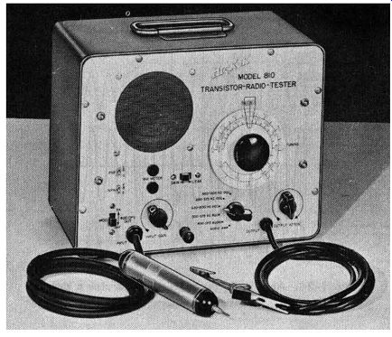
Fig. 25. Combination signal generator and signal tracer.
FREQUENCY-SYNTHESIZER GENERATORS
There is a growing trend to design lab-type signal generators as frequency synthesizers. These are generators of incremental frequency steps, and they are push-button operated.
They are used in radio sounding, radar testing, doppler systems, spectrum analysis, and various other applications. A frequency-synthesizer generator does not use tuned LC circuits. Instead, quartz crystals are employed to generate basic frequencies of extremely high accuracy. Harmonics from these crystal oscillators provide higher frequencies. Mixers, frequency dividers, and amplifiers are used to combine the various fixed frequencies to synthesize a desired frequency output from the generator.
Obviously, only discrete frequencies can be obtained from a frequency-synthesizer generator. On the other hand, an extremely large number of frequencies are available. Each avail able frequency has unusually high accuracy. The percentage accuracy is the same as the percentage accuracy of the quartz crystal oscillators. The smallest frequency step corresponds to the resolution of the frequency-synthesizer generator. A typical instrument has a resolution of 0.01 cps. Thus, when the appropriate buttons are pressed, you can obtain an output frequency of 30,000,000.00 cycles, or 30,000,000.01 cycles.
A little arithmetic will show that a generator with a range from 0.01 cps to 50 mc will provide a total of 5 billion discrete frequencies. A typical frequency-synthesizer has a maximum drift rate per day of 3 parts in 10°. Thus, this type of generator has an accuracy which is about the same as that of a high-quality secondary frequency standard. The circuitry of a frequency-synthesizer generator is necessarily complex, and hence is not covered in this guide. Interested readers may refer to engineering instrumentation texts for detailed information.
Also see: