AMAZON multi-meters discounts AMAZON oscilloscope discounts
Supersonic generators provide output frequencies above the range of audibility (above 15 kc). Thus, a supersonic genera tor might operate in the range from 15 kHz to 1 mHz. Familiar types of supersonic generators are commonly called audio oscillators, and they provide frequency coverage typically from 20 cps to 1 mHz. This terminology is a holdover from earlier practice in which audio oscillators covered a frequency range from perhaps 20 cps to 20 kc. Regardless of terminology, a generator that operates in the range from 200 kHz to 1 mHz is actually a signal generator by conventional standards. It is also called a video-frequency generator.
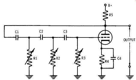
Fig. 1. Phase-shift oscillator.
BASIC CIRCUITRY
Many oscillators used in this type of signal generator have RC networks to provide feedback coupling between their out put and input circuits and to determine the frequency of oscillation. Such generators are called RC oscillators. Examples of RC oscillators are the phase-shift configuration and the Wien-bridge arrangement. A phase-shift oscillator is depicted in Fig. 1. It consists of a single amplifier tube and a phase shifting feedback circuit. We know that to sustain oscillation, feedback oscillator requires that the signal be fed back from the plate to the grid with a 180° phase shift. This function is performed by three RC sections.
Any one of these sections can be analyzed as shown in Fig. 2. When an AC voltage is applied to this circuit, a current having an amplitude determined by the total impedance of the circuit flows in the circuit. Because of capacitor C, the impedance is capacitive, and the current leads the voltage by 60°, as shown at B and C of Fig. 2. The voltage drop ER across resistor R is in phase with the current that flows through it.
Therefore, output voltage ER must also lead applied voltage E by 60°. When the output from this section is applied to a second similar phase shifter, another shift of 60° occurs, and the output of the second phase shifter is 120° ahead of applied voltage E. Similarly, the third phase shifter produces a total phase shift of 180°. When the resistance of R1, R2, and R3 (Fig. 1) is varied, the phase angle of the current flowing in the circuit is also varied. If the resistance were reduced to zero, the cur rent would theoretically lead the applied voltage by 90°. How ever, there are obvious reasons why a resistance value of zero is impractical. First, reducing R to zero would leave no impedance for developing a useful voltage. Second, with R equal to zero, the current would lead the voltage slightly less than 90° anyway, due to the inherent circuit resistance.
Therefore, in a generator circuit, resistor R is varied only down to the point where the current leads the voltage by about 60°. Of course, the value of R can be increased until there is very little phase shift. At a given setting, the amount of phase shift depends on the frequency. Thus, 180° phase shift (which provides oscillation) can occur at only one particular frequency. We see that the value of R corresponds to a certain frequency of oscillation. Of course, you can also vary the value of C to change the oscillating frequency.
In this type of generator, the oscillations are started by any slight circuit changes such as random noise voltages or small variations in plate-supply voltage. When such a disturbance occurs, the slight change is amplified, shifted 180° in phase, and applied to the grid of the tube for re-amplification.
This process continues until plate-current saturation is reached, after which the tube can provide no more output amplitude. Output is taken from the plate of the oscillator tube. It is then fed to a cathode follower, which provides isolation between the oscillator and generator output cable.
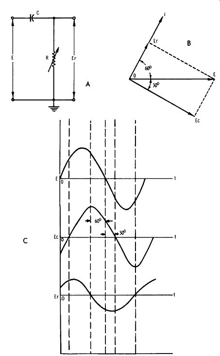
Fig. 2. Circuit action of an RC phase shifter.
WIEN-BRIDGE OSCILLATOR
Many generators utilize the Wien-bridge oscillator depicted in Fig. 3. It is a two-tube RC oscillator which is tuned by a resistance-capacitance bridge. V1 serves as an oscillator and amplifier; V2 is an inverter. The circuit would oscillate even without the RC bridge, because of the 180° phase shift produced by V1 and V2. However, this arrangement would not generate a specific frequency, nor would it generate a sine wave. Therefore, the bridge circuit is utilized to insure the elimination of all feedback frequencies except one. This one frequency is determined by the values of Rand C in the bridge.
The bridge oscillator in Fig. 3B facilitates circuit analysis.
A degenerative feedback voltage is provided by R3 and lamp Lp1•
The amplitude of this feedback voltage remains nearly constant for all frequencies, since the resistances are practically constant for all frequencies, and there is no phase shift across the voltage divider. Inverter tube V2 shifts the output of V1 by 180°. Thus, the voltage appearing across R2 in the bridge is in the correct phase to sustain oscillation. This action occurs when R1C1 = R2C2, The frequency at which the circuit oscillates is:
f = 1 --;- (2 pi R1C1)
Lamp Lp1 is a nonlinear resistance. Fig. 4 shows how filament resistance increases when the applied voltage is in creased. When more current flows, the filament becomes hotter, and this causes an increase in its resistance. It follows from Fig. 3 that the lamp compensates automatically for variation in circuit action, so that sufficient feedback voltage will always be applied to V2. When the current in the circuit increases, the lamp drops a greater voltage. This represents more de generation, which reduces the gain of V1 and holds the output signal at a nearly constant amplitude.
Tuning the generator to different operating frequencies tends to change the circuit current. In typical generators, C1 and C2 in Fig. 3 consist of a ganged variable capacitor.
When it is tuned, the capacitive reactances change, which tends to change the AC signal levels. However, the lamp resistance largely compensates for this change, so that the out put signal voltage remains about the same. Band-switching is accomplished in typical generators by use of different values of R1 and R2 in Fig. 3. This results in a different voltage divider action, which tends to change the circuit current.
Again, a compensating change in lamp resistance maintains the output signal voltage at about the same level.
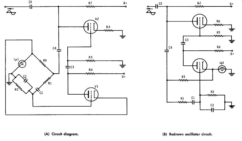
Fig. 3. (A) Circuit diagram. (B) Redrawn oscillator circuit.
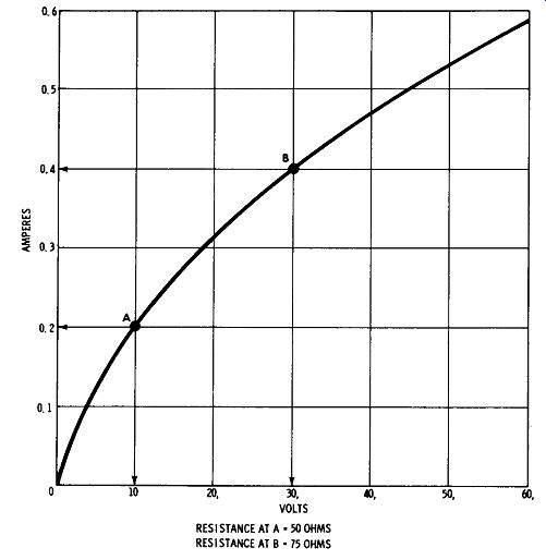
Fig. 4. Curve for positive temperature coefficient of resistance.
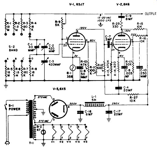
Fig. 5. Typical Wien-bridge generator.
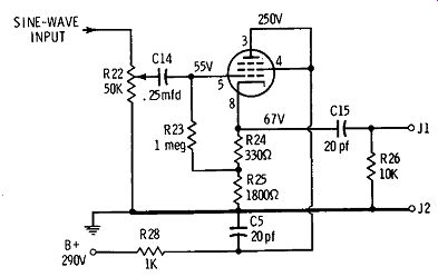
Fig. 6. Cathode-follower output.
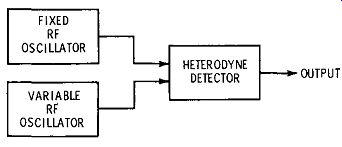
Fig. 7. Basic arrangement of a beat-frequency generator.
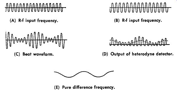
Fig. 8. Action of a heterodyne defector. (A) R-f input frequency. (B) R-f
input frequency. (C) Beat waveform. (D) Output of heterodyne detector. (E)
Pure difference frequency.
Note the typical Wien-bridge generator configuration shown in Fig. 5. You will observe that this is the same basic con figuration as in Fig. 3. Tuning is accomplished by variable capacitors C2 and C3, which are ganged. Trimmer capacitor C1 is provided for dial calibration. Band switching is pro vided by S2, which switches different values of resistance into the bridge circuit. Good sine waves require that the feedback be limited to a value which does not drive V1 and V2 past their region of linear operation. Accordingly, R9 is provided as a maintenance adjustment to set the feedback level correctly for a good waveform output.
Output is taken from the plate of V2 fed to a cathode follower, shown in Fig. 6. A 50K potentiometer is used in the grid circuit as an attenuator. A maximum of 10 volts rms is available from the cathode. Rated distortion is less than 1% , and the output level does not vary more than + 1.5 db from one band to the next. The hum level is less than 0.4 % of the signal-output level. You will find that the hum level in simple Wien-bridge generators does not come from the power supply, as might be supposed. Instead, it is due to stray-field pickup by the high-resistance bridge circuit (Fig. 5). Ample shielding is required to minimize the hum level.
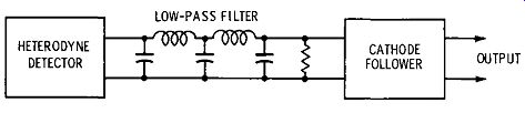
Fig. 9. Low-pass filter removes all but the difference frequency.
BEAT-FREQUENCY GENERATORS
Although they are less popular than in the past, beat-frequency generators are still used rather widely. The basic arrangement is depicted in Fig. 7. Two r-f oscillators are employed, and their combined outputs are fed to a heterodyne detector. Fig. 8 shows the action of a heterodyne detector.
The r-f input frequencies are shown in Figs. A and B. These frequencies mix together to form a beat waveform (Fig. C), which is the same as a modulated r-f wave. Since the heterodyne detector is a rectifier, half of the signal excursion is rejected. In turn, the output waveform has an envelope which varies at the difference between the two r-f signals.
Output from the heterodyne detector is shown in Fig. 8D. This waveform contains not only the difference frequency, but also the sum frequency, and various harmonics of both the sum and difference frequencies. Hence, to obtain the pure difference frequency (Fig. SE), a low-pass filter is employed, as shown in Fig. 9. The low-pass filter consists of series coils and shunt capacitors, terminated in the characteristic resistance of the filter. It has a cutoff frequency beyond which no frequencies can pass. However, it imposes practically no attenuation on frequencies below the cutoff frequency. Details of low-pass filters cannot be explained here, but interested readers may refer to guides such as 101 Ways to Use Your Ham Test Equipment, published by Howard W. Sams & Co., Inc.
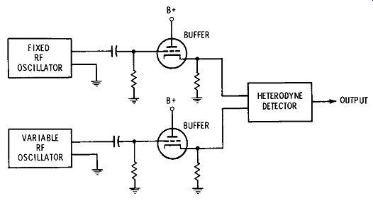
Fig. 10. Buffers Isolate the r-f oscillators.
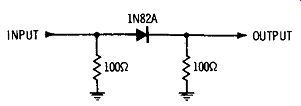
Fig. 11. Simple heterodyne detector.
Several requirements must be met in the design of a beat frequency generator. The stability of the r-f oscillators must be maximized. For example, the fixed oscillator in Fig. 7 might operate at 100 mHz. In turn, the variable oscillator might be tuned to operate at 100.05 mHz. The difference-frequency output is then 50 kc. If either of the r-f oscillators drifts 10 kc, the output frequency will be in error by 20%. This is a drift of only 0.1 % in the r-f oscillator frequency. Hence, there is a very demanding design problem.
Another requirement which must be met is ample decoupling of the two r-f oscillators. We know that when two oscillators are coupled and are tuned to the vicinity of the same frequency, the oscillators tend to synchronize at the same frequency. This is called pulling and locking. When oscillators pull, the output frequency changes. If they lock, output from the heterodyne detector falls to zero. Hence, buffers are used to isolate the r-f oscillators, as shown in Fig. 10. In this example, the buffers are cathode followers. However, RC amplifiers with very low values of plate-load resistances are also used in some generators. In such case, pentodes are preferred to triodes, in order to obtain better isolation.
Various types of heterodyne detectors are used. Some generators use a simple semiconductor diode in a low-resistance circuit, as shown in Fig. 11. Other generators use converter tubes. The advantage of a tube is that it provides a gain instead of an insertion loss. To obtain a good sine-wave output, a heterodyne detector must not be overloaded. It is also helpful to make the r-f input voltage from the fixed oscillator considerably less than that from the variable oscillator. The r-f oscillators themselves must supply a good sine wave. When a semi conductor diode is used as a heterodyne detector, it is often helpful to supply a DC bias. The necessary bias voltage depends on the characteristic of the diode.
The diode is operated on its forward interval. Best hetero dyne-detector action occurs when the diode is forward-biased to the most rapidly curving point on its knee. Then, when the applied r-f voltages have suitable amplitudes, a good sine wave difference frequency is produced. By the same token, converter tubes used for heterodyne detection must have optimum electrode voltages to obtain good output waveforms.
You will find that all beat-frequency generators have some cross-beats present in the output. Good design can hold these spurious outputs, or birdies, to a comparatively low level.
Cross modulation occurs because the r-f signals are rectified.
In turn, harmonics are generated. These harmonics can beat together at a frequency in the vicinity of the difference frequency. To minimize cross modulation, the operating point of the heterodyne detector must be carefully selected. Reduced drive to the detector also helps to minimize or eliminate cross modulation.
All video-frequency FM generators operate on the beat frequency principle. This is a necessary design because phase shift or Wien-bridge oscillators cannot be deviated over a substantial range without band-switching. If the deviation is set to zero, the generator can be used as a beat-frequency c-w generator. Since its frequency stability is less than that of a Wien-bridge oscillator, however, most FM generators are not recommended for c-w operation.
Also see: Electrical / Electronic Measurements and Instrumentation