AMAZON multi-meters discounts AMAZON oscilloscope discounts
(Section 20 of our "Electrical Transmission / Distribution" series on industrial-electronics.com)
1. INTRODUCTION
This section describes how to apply the latest Electromagnetic Compatibility (EMC) Standards to Transmission and Distribution Equipment.
The subject of EMC comes under EMC Directive 89/336 EEC for all European Union (EU) countries. This is being replaced by a new version, 2004/108/EC, which is similar in many respects. In the USA the Federal Communication Commission (FCC) standards apply, elsewhere European or International Electrotechnical Commission (IEC) standards are commonly used. Both sets of standards are similar and many of the European standards are identical to the corresponding IEC standards.
In brief, the EU EMC directive requires that all electrical and electronic equipments constructed for use in any EU country must ensure:
_ The electromagnetic disturbance generated by the apparatus does not exceed a level allowing radio and telecommunications equipment and other apparatus to operate as intended (i.e. to limit the electromagnetic noise from the equipment).
_ The apparatus has an adequate level of intrinsic immunity to electro magnetic disturbance in the intended environment enabling it to operate satisfactorily (i.e. to ensure adequate screening and noise immunity in the operational environment).
The effect of conducted electromagnetic disturbances on power systems is discussed separately in Sections 24 and 25 (Power quality).
Many good theoretical and descriptive books related to EMC already exist [Ref. 1-9]. This section describes the application of the theory to real practical transmission and distribution examples and typical measurements that may be made on site.
2. STANDARDS
Tables 1-3 list current EMC national and international standards which are relevant to transmission and distribution projects. It’s the requirement of the EU Commission that all standards will be common throughout the Community. To this extent, various committees and working parties have been convened and tasked to meet this requirement. Where such common standards are not in existence, national standards will be used.
Engineers concerned with substations in a railway environment should note that the applicable series of standards (EN 50121 EMC in railway applications) has not been harmonized. The implications of this are discussed in Section 3.
Although the effects of non-ionizing electromagnetic radiation (NIEMR) on workers have not as yet come under the auspice of an EU Directive (the EMC Directive 2004/104/EC and its associated guidance document _ EMC Directive 2004/108/EC _ have been published and have come into force), the list of standards includes reference to the National Protection Laboratory guidance document for Exposure of Humans to Electromagnetic Fields. As the measurement of the fields to which these documents refer is similar in some respects to those related to EMC testing, this section will also address the relevance of these requirements.
Guidance on the choice and applicability of generic EMC standards is available in CENELEC Report R110-002 [9].
====
TBL. 1 UK National Standards
Document Number:
BS 5049a BS EN 61000 BS EN 50121 NRPB-GS11b
Document Title:
Radio interference characteristics of overhead power lines and high voltage equipment.
Electromagnetic compatibility _ British standard is identical to EN 61000 and based on IEC 61000c Railway applications _ electromagnetic compatibility Guidance as to restrictions on exposures to time varying electromagnetic fields and the 1992 recommendations
====
TBL. 2 Generic Standards for Apparatus
Document Number Document Title EN 61000-6-1 Immunity for Residential, Commercial and Light-Industrial Environments EN 61000-6-2 Immunity for Industrial Environments IEC 61000-6-3 Emission Standard for Residential, Commercial and Light Industrial Environments EN 61000-6-4 Emission Standard for Industrial Environments EN 61000-6-5 Immunity for Power Station and Substation Environments
===
TBL. 3 International Standards (for Equipment) Document Number Document Title EN 55022a Limits and Methods of Measurement of Radio Interference Characteristics of Information Technology EN 55011a Radio Frequency Limits and Methods of Measurement of Electromagnetic Disturbance Characteristics of Industrial, Scientific and Medical Radio Frequency Equipment EN 55024a Information Technology Equipment. Immunity Characteristics.
Limits and Methods of Measurement IEC 61000-1b EMC _ General IEC 61000-2b EMC _ Environment IEC 61000-3b EMC _ Limits IEC 61000-4b EMC _ Testing and Measurement Techniques IEC 61000-5b EMC _ Installation and Mitigation Guidelines IEC 61000-6b EMC _ Generic Standards CISPR 18 Radio Interference Characteristics of Overhead Power Lines and High Voltage Equipment
===
3. COMPLIANCE
The EMC directive has legal implications on both its implementation and the meeting of the standards set. Substations are considered as fixed installations as defined in the Guidelines to the Directive [8]. Thus, where the directive applies, the transmission and distribution engineer has a liability to ensure that compliance with the directive is met and maintained throughout the operating life of the apparatus. In many other territories compliance would be seen as good practice.
For compliance with product-specific or generic standards, compliance will normally be achieved through testing supplied equipment to harmonized EMC standards, with the provision of an EMC 'Declaration of Conformity' (DoC).
Note however that for railway substations compliance is necessarily through a Technical Construction File (TCF) as EN 50121 is not a harmonized standard.
For a complete installation, proof of compliance with the required criteria, as summarized in Section 20.1, may be achieved by preparing firstly an
'EMC Management Plan', which will show how the question of meeting EMC requirements will be organized, worked out and documented through out the design, construction and operation of the project. Secondly, an 'EMC Control Plan' will include DoCs, TCFs, risk analyses measurement results, etc. In general, installations can be proven to comply with the essential protection requirements of the EMC Directive, where it can be demonstrated that compliant products are installed to good engineering practice.
4. TESTING
4.1 Introduction
Testing of apparatus can fall into two distinct categories:
_ Individual apparatus tests.
_ In-site apparatus/system testing.
The concepts of individual apparatus testing, for both emissions and immunity, are well defined in the various test standards. TBL. 2 lists the Generic Standards which are used to conduct these tests. As the requirements are accepted internationally, the methods and procedures are not discussed in this section. Suffice it to say that testing is required to be performed in test houses that have been audited and accredited as suitable to conduct the tests identified in the relevant standards.
The Generic Standards are to be used where no product standard exists.
In many cases this situation will arise within typical power and distribution designs. Depending on the installation location of the system being designed, the responsible engineer will have to decide which Generic Standard he or she elects to follow.
Within these standards there are references to the general international standards which are listed in TBL. 3.
Once the different equipments have been approved against their individual test standards, it’s not acceptable for the design engineers to conclude that all EMC responsibilities have been met. It’s the interconnection of the various equipments together which will still require a confirmatory assessment and testing. As all systems and their associated interconnections are different, there may be existing conditions which are different to those considered in the standards.
However, with the design engineer's knowledge of the standards required for his various system equipments, judgmental on-site testing can be per formed to ensure the requirements of the EU Directive, as paraphrased in Section 1, are achieved.
4.2 Magnetic Field Radiated Emission Measurements
In the power distribution environment, magnetic field emission measurements are normally conducted over the frequency range 20 Hz to 50 kHz where installation design and health effects are considered. As a transmission and distribution network could be spread over large distances it’s necessary to evaluate the 'worse case' condition. This is normally performed using hand-held, battery-driven equipment. Typical equipment is shown in FIG. 1. It should be noted that EMC product approval magnetic field emission requirements are limited to lighting equipment and industrial equipment containing wanted radio frequency sources and special test facilities or test ranges are required.
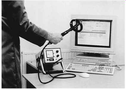
FIG. 1 Magnetic field portable measurement equipment. (other EMF measurement devices)
The test engineer would move around the area under investigation with the antenna probe held in a fixed orientation. The probe consists of three orthogonal coils, so the displayed information is the sum of the fields being radiated at that particular point irrespective of their frequencies. The reading displayed on the unit is calibrated and shown in dB picoTesla and is therefore directly related to the standard. The design engineer can deduce two criteria from these results:
_ If the displayed information is 40 dB, i.e. 100 times, below the design level, he or she may decide that further testing is not required.
_ If the displayed level is closer to the design level than the 40 dB, or if more definitive measurements are required, he or she can place the specialist measurement equipment in the defined 'worse case' area.
FIG. 2 shows a typical layout of test equipment suitable for the detailed measurements.
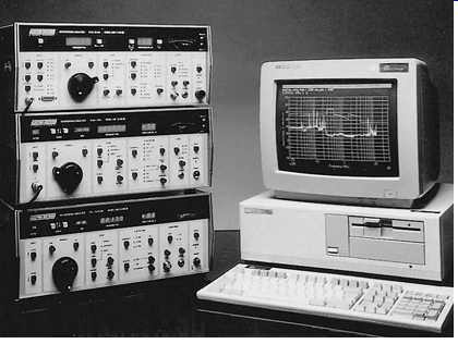
FIG. 2 EMC emissions test equipment layout. Highly accurate receivers
and frequency/ amplitude plot recorded on computer. (similar EMC test equipment)
Measurements are made whilst the loop antenna is fixed in each of its polarizations. The receiver is then stepped through the defined frequency range. Data, on the levels of radiated energy for each frequency step, are gathered and stored within the computer. The data can be retrieved and presented in graphical for mat for analysis against the design limits at a later date. A typical plot of field measurements with no substation equipment energized is shown in FIG. 3a. FIG. 3b shows the radiated fields with the substation equipment energized.
It must be noted that, although for convenience the peak levels of radiated energy are normally checked against the specification or design limit, measurements related to the Health Protection Agency (HPA, and previously the National Radiological Protection Board (NRPB)) Vol. 15, No. 2 document have to be calculated and weighting factors taken into consideration for the different harmonic frequencies involved.
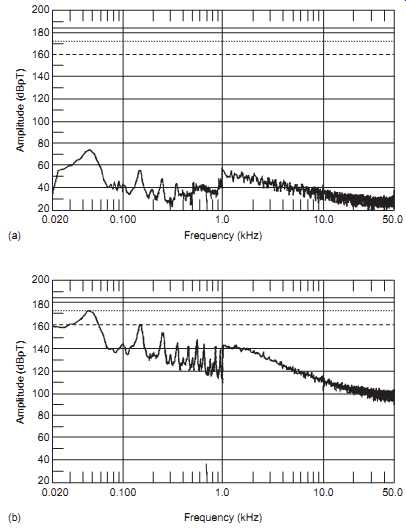
FIG. 3 (a) Ambient magnetic field measurement. (b) Equipment magnetic
field measurement.
4.3 Electric Field Radiated Emission Measurements
Power distribution and transmission technologies involve frequencies normally from 50 Hz and up to the 25th harmonic but some associated electronic equipment may contain high frequency sources that could cause interference to radio systems. The EU Directive is, in particular, concerned with the interference to communication equipment and requires measurements in the frequency range 30_1000 MHz. Also, with the development of more sophisticated electronic control equipment in the power industry, the reduction of radiated higher frequency electric fields becomes more critical; e.g. clock frequencies and fast leading switching pulse waveform edges used by microprocessor equipments must not be degraded. In substations or power stations, it’s more important to ensure that electronic systems have adequate immunity to the local disturbance fields and there is a lower level of requirement to control emissions from supplied equipment and switching devices.
As with the measurement of magnetic fields, initial ambient electric field data may be gathered using portable equipment. Care must be taken in the use of this equipment in order to avoid the human body affecting the results.
Use of this type of equipment for anything other than 'worse case' location identification (e.g. for product compliance with relevant standards) can only be performed with the antenna probes mounted on wooden tripods on a calibrated test site prior to results being taken.
Having identified the 'worse case' locations, specialist equipment testing can now be performed. Whilst equipment suitable for these tests is similar to that used for the magnetic field testing, the main area of change is in the type of antennae. The antennae used relate to the frequency bands in which the testing is to be performed and use of an antenna outside its operation frequency band must not be carried out. FIG. 4 shows antennae suitable for use in the frequency bands from 20 Hz to 1,000 MHz.
Data gathered during these tests can be evaluated later and checked against the design limits. Typical plots obtained during the testing would be similar to those shown in FIG. 3 with amplitude measured in dBµV/m against frequency.
4.4 Conducted Emission Measurements
The levels of harmonic current emissions and flicker are set out in IEC 61000-3-2 and 61000-3-3. These have been issued as harmonized European standards EN61000-3-2 and EN611000-3-3 and are being incorporated as part of the EMC directive. The consequent levels of harmonic and unbalance voltages which can be reflected back into the supply network are controlled by the different distribution networks. Typically, IEC 60034-1 (rotating electrical machines) allows for no more than 1% unbalance on polyphase voltage systems and that the instantaneous peak harmonic voltage is less than 5% of the fundamental peak voltage. See also Sections 24 and 25.
The EU Directive defines the conducted transients which an apparatus is allowed to generate into the local environment. TBL. 3 lists the appropriate international standards. These ensure the general requirements, as paraphrased in Section 1, are achieved.
The concepts of these tests are well defined in the various test standards.
As these requirements are accepted internationally, the methods and procedures are not discussed in this section. Suffice it to say that testing should be performed by persons or test houses who will have been audited and approved as suitable to conduct the tests identified in the relevant standards.
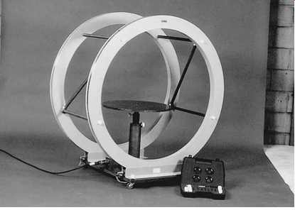 FIG. 4 Helmholtz coils (for creating an environment free of the earth's magnetic field). (other Helmholtz coils)
4.5 Immunity Testing
Once the apparatus has been installed within the confines of the design engineer's system, it becomes more difficult to perform radiated and conducted immunity measurements. It may be argued that, provided the equipment operates within its own confines and under all definable conditions, further testing is not required. Problems of taking this argument to its final conclusion occur when systems are shown to be susceptible in operation. It may now be necessary to conduct localized immunity testing in order to satisfy legal and contractual requirements.
Testing at this level can only be achieved by using the principles set out in the various product EMC standards. With conducted immunity testing, provided the relevant cables can be accessed, test methods and procedures identified in these documents can be followed.
Radiated immunity testing presents a larger problem. It’s forbidden, by the Wireless Telegraphy Act, to transmit signals into the environment unless a license is obtained. Further, if a license is granted, then it will only cover a defined and stipulated frequency, which is of no use to the design engineer.
Other test methods which will approximate to the radiated immunity testing must be used. One such method, which was developed for the aircraft industry so as to overcome this particular problem, is known as Bulk Current Injection. In this method, relatively low levels of the interference signals can be injected onto the system cable form with the use of a current transformer.
Similarly, the interference signal may be coupled into the cable form using a galvanic connection. These test methods are covered in the associated apparatus test standard IEC 61000-4-6.
5. SCREENING
5.1 Introduction
In the design of any apparatus and the subsequent system, screening will be used to overcome potential but possible under-evaluated EMC concerns. Care in the use of the screening of both cables and equipment must be taken. Poor engineering of screening may cause more problems than they resolve.
Texts have been written, which investigate the theory of screening and provide calculated examples of achieving design limits..
General points which should be considered in deciding on the level and type of screening are as follows.
5.2 The Use of Screen Wire
All wires including the screens are at some point terminated. The termination of the screen will be critical to its operating efficiency. Control and communication cable screens should only be connected at one end, thereby reducing the probability of circulating currents. Where this conflicts with safety 'step and touch' potential requirements the bonding of screens may take place within the run lengths of the cables and/or secure 'gapping' of the screen may be incorporated ( FIG. 5). If the cable is terminated at a multiway connector, then the connector should be enclosed in a metal housing; this housing acts as a continuation of the cable screening. Where screened connectors cannot be used and wire 'tails' are used to terminate the cable screens, the tails must be kept short, less than 3 cm, and taken to known clean earth points ( FIG. 5).
===
Equipment room Amour gap Amour bond* Panels Note: inner screen not terminated Main cabinet Remote cabinets Earth bar Earthing system Short tails Legend key
* Position of amour bond may be moved to ensure safety step and touch requirement Local earths Coaxial amour termination via gland Cable screen Cable amour Cable conductor cores
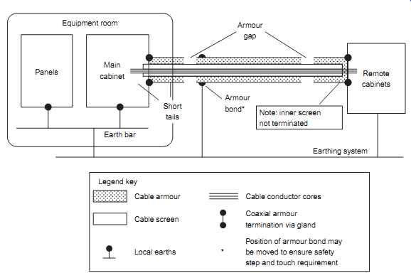
FIG. 5 Screened and armored screen earthing arrangements.
===
5.3 The Use of Screen Boxes and Faraday Enclosures
Any aperture in the box will, unless properly screened, degrade the effectiveness of the box. Areas of particular note include lids which must be fitted with EMC gaskets and close spacing of fixing screws ( FIG. 6). The entry ports of any cables are of importance. Where screen cables are being brought directly into the unit, continuity of the screening at the entry gland must be maintained by a 360-degr. peripheral glanded connection.
===
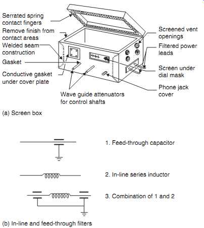
FIG. 6 (a) Screening and filtering of boxes. (b) Typical EMC suppression
filters. (browse/buy
EMC suppression filters)
1. Feed-through capacitor
2. In-line series inductor
3. Combination of 1 and 2
Screened vent openings; Filtered power leads; Screen under dial mask; Phone jack cover; Wave guide attenuators for control shafts (a) Screen box; (b) In-line and feed-through filters ; Conductive gasket under cover plate; Gasket; Welded seam construction; Remove finish from contact areas; Serrated spring contact fingers
===
Where unscreened cables are being used, each wire must be taken into the box via EMC filters ( FIG. 6a).
FIG. 6b shows the schematic diagrams of three typical in-line, or feed-through, filters used in EMC. The general rules that can be taken in the design of transmission and distribution projects are that:
_ In-line feed through capacitors will short circuit high frequency signals to earth.
_ In-line inductors will act as high impedances to the fast rise edges of signal and therefore prevent their transmission into the culprit circuitry. The high frequency performance of the inductor may be limited by the self capacitance of the windings.
5.4 The Use of Screen Floors in Rooms
If a substation design requires the use of screen metal false floors within a control room containing electronic equipment, it’s essential that the design engineer is conversant with the reasons for this type of floor. If it’s required simply to provide a safety earth for both the users and the equipment, then the construction of the floor need only take into account its need to maintain low frequency, low impedance paths. This will include the installation of earth connections to the floor with particular care being taken to ensure continuity is maintained when screen tiles are removed due to maintenance or installation of new equipments. The same care needs to be taken where tiles are cut to allow for the passage of cables and air ducts. For this type of floor a 'stringerless' construction may be used where the tiles are mounted on individual corner pillars ( FIG. 7a).
View A shows a typical method of connecting the pillars to an earth termination wire. Maintenance may be kept to a minimum with standard cleaning of the tiles and pillar heads only when a tile is removed.
Where the floor is to be used to screen the equipment in the room from any conducted or re-radiated noise associated with cables under the floor, then different design criteria are required from those described above. It’s recommended that such a requirement will force the design engineer into using a 'stringer' floor construction ( FIG. 7b). Should the above 'stringer less' construction be used then each pillar must be taken to the common ground point. The area above the screen floor should now be considered as the interior of a screen box or Faraday enclosure. Hence cables entering this area must be glanded and filtered in a manner as described above. Where air ducts are set in the floor, the apertures must be constructed as an EMC wave guide. FIG. 8 shows a 'honeycomb' construction of a typical ducting aperture. These have known filtering characteristics and are ordered and installed such as to maintain EMC security over the frequency ranges being considered in the room's design parameters.
6. TYPICAL USEFUL FORMULAE
Measurements and calculations used by EMC engineers are normally in the units of decibels, amperes/meter and volts/meter. The following formulae follow these precedences.
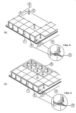
FIG. 7 (a) Typical stringerless screen floor construction. (b) Typical
stringer screen floor construction. Key: 1, screen floor tiles; 2, mounting
pillars; 3, earth connection wire; 4, main earth wire; 5, metal support
stringers.
FIG. 8 Typical honeycomb ducting construction. Foil direction of upper honeycomb; Foil direction of lower honeycomb
6.1 Decibel Reference Levels
These are defined as follows:
For a power ratio:
dB510 log10 (Pmeasured/Preference) since power (P) is proportional to the square of the voltage(V2), then for a voltage ratio:
dB520 log10 (Vmeasured/Vreference) TBL. 4 provides a quick reference for levels above 1 dBµV.
---
TBL. 4 Decibel Reference Levels 3dB51.4 µV40dB5100 µV90 dB531.6 mV 6dB52.0 µV50 dB5316 µV 100 dB5100 mV 10 dB53.16 µV60 dB51.0 mV 120 dB51.0 V 20 dB510.0 µV70 dB53.16 mV 140 dB510 V 30 dB531.6 µV80 dB510 mV 160 dB5100 V
---
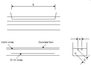
FIG. 9 Drawing of corridor showing cable layout.
6.2 Field Strength Calculations
At the low frequencies of transmission and distribution projects we can assume that the distance at which the measurement is taken is very much less than the length of the culprit circuit wires ( FIG. 9).
Very close to the wire, for R,(?/2),D, the radiation from a long wire per ampere equation is:
... i.e. an 1/R decrease independent of frequency. The electric field E can only be determined approximately from the circuit impedance.
At intermediate distances, for R,(?/2).D, the radiation from a pair of wires may be calculated from:
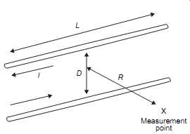
FIG. 10 Simplified geometry of long radiating wires.
6.3 Mutual Inductance Between Two Long Parallel Pairs of Wires
The mutual inductance between sets of long parallel pairs of straight wires can be calculated from the equation:
6.4 Attenuation Factors
where:
µ5 permeability of shielding material relative to copper
t5 thickness of shielding material (mils)
r5 distance from source to shielding material (mm)
f5 frequency in Hz
G5 shielding material conductivity relative to copper
Many shielding manufacturers, and in particular manufacturers of shielded wires, will have standard graphs for the above calculations and these should be used whenever possible.
The attenuation factors of any metal at low frequencies can be provided by the sum of absorption losses plus reflective losses.
Absorption losses can be calculated from:
7. CASE STUDIES
7.1 Screening Power Cables
7.1.1 Concern
The general cable configuration is shown in Figs. 9 and 11.
Due to system design criteria the following conditions have been forced on the installation of the equipment:
_ Two sensitive signal cables transmitting information to nearby receiver coils are placed within 1.0 meters of a three-phase 21 kV cable for a distance of 60 meters. As the signal cables are operating on the principle of radiating energy signals to the receiver coils, they cannot be screened or in any other way protected from the noise. The operational frequency band of the victim system is 7 kHz to 12 kHz.
_ The 21 kV power cable is feeding multiple systems including noise generators such as pumps, motors and transformers.
7.1.2 Requirements
Noise which may be present on the 21 kV cable must not be induced on the signal carrying wires or radiated such that it may interfere with the receiver coils.
7.1.3 Solution
Due to the low operational frequency of the signal cables and to ensure the above requirement is achieved, it’s necessary to place the 21 kV cable in a solid metal pipe. A pipe having an internal diameter suitable for the 75 mm 21 kV cable and having a wall thickness of 7.6 mm was found to be available.
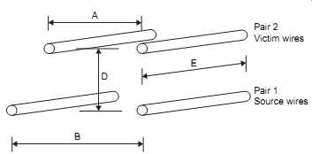
FIG. 11 Cable layout for calculation.
7.1.4 Known Factors and Assumptions
The following initial data needed to be determined, and, as this is an evaluation to ensure proposed solutions are acceptable, engineering assumptions are made.
1. What thickness of steel tube will be used? 7.6 mm _ Due to existing availability
2. What is the sensitivity of the receiving system? 125 µA/m at 7_12 kHz This sensitivity is obtained from the victim's data sheets.
It’s decided that any induced field at 10 kHz should not exceed 1/100th, 40 dB, of this value.
3. What is the minimum current in the signal cables? 150 mA This figure is obtained from the victim's data sheets.
4. How far are the signal cables from the 21 kV cable?
0.945 m
Obtained from detailed system drawings.
5. How far apart are the signal cables? 1.7 m Obtained from detailed system drawings.
6. What is the harmonic current at 10 kHz associated with the 21 kV cable? As no details are available use 0.1% of full load
7. What is the impedance of the signal cables? 50 ohm, 5 ohm, and 0.5 ohm
The victim's data sheets showed the minimum impedance to be 50 ohm. Calculations at 5.0 ohm and 0.5 ohm have been used to ensure a safety margin.
8. Due to the close proximity of the interference source with the victim it’s assumed that the two sets of cables are parallel. This allows for standard equations to be used in the initial calculations.
7.1.5 Proof of Suitability for Conducted Noise in Victim Wires
The mutual inductance between sets of long parallel pairs of straight wires can be calculated from the equation provided in Section 6.3:
From the above equation, it’s possible to calculate the voltage and cur rent induced in Pair 2, i.e. the victim wires:
I1 5 maximum current flowing in Pair 1 T5rise time of the maximum current flowing in Pair 1 in nanoseconds Z5 impedance of the Pair 2 victim circuits in ohms Using the above equations and data the worse case current can be estimated at 10 kHz:
7.1.6 Proof of Suitability for Radiated Noise in Victim Receiver Coils
The magnetic field set up by the 21 kV cable at 10 kHz is:
Thus using a steel pipe with a wall thickness of 7.6 mm provides sufficient attenuation (1,002 dB) to achieve the objective of protecting the receiving coils from the 21 kV noise.
7.2 Measurement of Field Strengths
The case study investigated in this section deals with the initial measurement of magnetic fields within the confines of a substation switchyard. Identical methods could be used for the measurement of both magnetic and electric field strengths in any area, and is particularly useful in the measurement of field strengths produced by long distribution cables.
FIG. 12 shows the basic layout of the switchyard containing static VAr compensation air core reactors and capacitor banks. It’s required to determine the levels of magnetic field around the various perimeter fences to ensure those levels prescribed by the latest Health Protection Agency (HPA)/ National Radiological Protection Board (NRPB) guidelines are not exceeded.
Using the portable test equipment shown in FIG. 1, the engineer deter mines the points where the maximum total field is monitored. Due to the wideband operation of the equipments it must be remembered that the measurements show the fields at the fundamental and all harmonic frequencies.
Points 1 to 4 in the figure are typically where the maximum field strengths will be observed, this being due to the large inductors within the yard and their location with respect to the fencing.
In the particular case study, the levels monitored were:
Position Level mT
The measurement observed at position 2 was above the 0.8 mT reference level proposed by the NRPB (Note: current HPA levels may be lower).
With this apparently high level, it’s considered advisable to take detailed measurements at point 2 using the specialist measurement equipment.
FIG. 3b shows the graph obtained from these measurements. A number of issues can be determined from this result. Firstly, it’s predominantly the fundamental 3rd to 17th harmonics which are being radiated. Secondly, none of the levels reach the 0.8-mT level, i.e. 178 dBpT.
The HPA guidance document recommends the following:
Where exposure occurs at more than one frequency, the exposure can be considered to be less than the effective reference level if:
XRf # 1 where Rf is the ratio of the measured value to the reference level in the appropriate unit at frequency f.
Using the information taken from FIG. 3b, and using the above equation, it can be shown that the summation is approximately 2.3 mT, i.e. an unsatisfactory condition. Even if the fundamental frequency component is removed from the equation the total field density is above 1.8 mT.
Restrictions can be placed on the access of personnel within the area such that they are kept in a narrow corridor around the building. Further measurements were taken at position 5 with the results shown in FIG. 13.
If the total field density is now recalculated we find the answer is approximately 0.11 mT, i.e. a satisfactory condition.
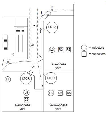
FIG. 12 Layout of power distribution yard.
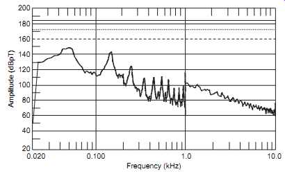
FIG. 13 Measurement of equipment magnetic field.
REFERENCES:
1. White DRJ. Electrical noise and EMI specifications, vol. 1; 1971.
2. White DRJ. Electromagnetic interference test methods and procedures, vol. 2; 1980.
3. White DRJ. Electromagnetic interference control methods and techniques, vol. 3; 1973.
4. White DRJ. Electromagnetic interference test instrumentation systems, vol. 4; 1980.
5. White DRJ. Electromagnetic interference predictions and analysis techniques, vol. 5. 1972.
6. White DRJ. Electromagnetic interference specifications, standards and regulations, vol. 6; 1975.
7. White DRJ. EMI control methodology and procedures, vol. 8. Gainsville, VA, USA: Control Technologies, Inc.; 1985.
8. Paul CR. Introduction to electromagnetic compatibility. 2nd edition. New Jersey, USA: J Wiley & Sons, Inc.; 2006.
9. Ott HW. Noise reduction techniques in electronic systems, J Wiley & Sons, 1988/ Electromagnetic Compatibility Engineering. New Jersey, USA: J Wiley & Sons, Inc.; 2009, ISBN 978-0-470-18930-6.
10. European Commission. European commission guidelines on the application of council directive 89/336/EEC 3 May 1989 on the approximation of the laws of the member states relating to electromagnetic compatibility and Amendments 92/31/EEC, 93/68/EEC, 93/97/ EEC; 1997.
11. CENELEC. Guide to generic standards, Report R110-002; 1993.
12. ICNIRP. Guidelines for limiting exposure to time-varying electric, magnetic, and electro magnetic fields (up to 300 GHz). Health Phys 1998;74:494_522.
13. Advice on limiting exposure to electromagnetic fields (0_300 GHz). Documents of the NRPB/HPA. Vol 15, No. 2; 2004.
Prev. ------ Next