AMAZON multi-meters discounts AMAZON oscilloscope discounts
Three different types of transducers are used for measuring vibration. These are
• noncontacting proximity probes (normally eddy-current type)
• velocity pickups
• accelerometers (piezoelectric, capacitance, or strain gauge, with the piezoelectric type normally being preferred).
Each type has its advantages and disadvantages. Choice to a large extent thus depends on the particular application and the most significant parameter to be measured. The three parameters involved in vibration are amplitude or displacement, frequency or repetition rate, and phase in the case of multiple vibrations, which gives the relationship of one vibration to the other(s).
Directly measurable quantities are displacement, velocity, and acceleration, which are all interrelated and also related to frequency. Equal displacements at two different frequencies, for example, don't result in equal vibration velocities or vibration acceleration.
VIBRATION MEASUREMENT
Probably the simplest way of measuring vibration is by displacement (and also determining the frequency). But this is not necessarily the best way. Measuring vibration velocity or vibration acceleration may be better in some cases, and if displacement (amplitude) is also needed to be known, this can be derived from velocity and acceleration. Similarly, if acceleration is measured, then integrating this signal once will give vibration velocity. With suitable circuitry an accelerometer can thus provide both acceleration and velocity readout.
Without going too deeply into details, the advantages and disadvantages of measuring vibration displacement, velocity, or acceleration can be summarized as follows:
-- Measuring displacement gives a signal that's proportional to displacement only. The advantages are:
• easy to understand
• easy to specify
• low-impedance signal easy to handle and display
The disadvantages are
• difficult to measure directly
• not related directly to vibration energy
• low sensitivity
• difficult to install. Linear variable-differential trans - formers or potentiometers require coupling to base reference.
-- Measuring velocity gives a signal that's proportional to displacement and frequency of vibration. The advantages are
• directly related to vibration energy
• sensor easy to install
• low-impedance signal easy to handle
• sensor normally supplied critically damped
The disadvantages are
• limited frequency response (8 Hz to 1 kHz),
• relatively large sensor required (not necessarily a disadvantage in industrial applications)
-- Measuring acceleration gives a signal that's proportional to displacement energy over (frequency)^2 The advantages are
• wide frequency response
• can use small lightweight sensors of robust construction. The disadvantages are
• not directly related to vibration energy
• more complex instrumentation signaling equipment required
• low output at very-low frequencies
• susceptible to thermal effects
Measurement of vibration velocity thus enables vibration energy to be determined, independently of the frequency of vibration, for any given system of constant mass. Velocity is proportional to the frequency of vibration for any given system of constant mass and constant amplitude. This is also illustrated by the frequency relationship diagrams of Fig. 28-1.
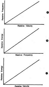
Fig. 28-1. For a system having constant mass and constant amplitude
of vibration, measurement of vibration velocity will yield a direct
indication of vibration energy. This Is indicated by the linear relationships
at A and B; the result (C) is that vibration energy is linearly proportional
to vibration velocity.
This relationship is readily demonstrated by electromagnetic vibrations, such as used for calibration purposes. Here, when frequency is increased at a constant power level (constant energy for unit time), vibration displacement decreases, vibration velocity re mains constant, and vibration acceleration increases.
Vibration velocity measurement, therefore, is particularly applicable where the mechanical system concerned may vibrate at an unknown or variable frequency, or where the fundamental frequency of the system can't be predicted.
A further advantage offered by vibration velocity measurement is that the sensor is normally critically damped so that the chance of resonance affecting the readings is eliminated. With an undamped sensor and the presence of a broad spectrum of vibration, false readings may be obtained. However, vibration acceleration measurement is commonly preferred because of its wide frequency response and the fact that the sensor(s) used can be quite small, lightweight, and robust.
With the above in mind we can then look at the three different types of transducers involved and their advantages and disadvantages.
-- Proximity Probe (Displacement Pickup). The advantages are
• noncontacting
• measures motion directly
• measures in engineering terms
• solid-state device with no moving parts
• measures dynamic motion and average position Simultaneously
• excellent frequency response
• small size
• well suited to machine environments
• easily calibrated
• accurate low-frequency amplitude and phase-angle information
• high-level low-impedance output
The disadvantages are
• tends to be excessively sensitive to shaft runout
• can be sensitive to shaft material
• requires external power source
• can be difficult to install
• limited maximum service temperature (typically 175 deg C. or 350 deg F. for the probe and 100 deg C. or 212 deg F. for the driver)
-- Velocity Pickup. The advantages are
• ease of installation
• strong signal in mid-frequency range
• no external power required
• may be suitable for high-temperature environment
The disadvantages are
• relatively large and heavy
• sensitive to input frequency
• relatively narrow frequency response
• moving part device (subject to wear)
• difficult to calibrate
• measures dynamic motion only
-- Accelerometers. The advantages are
• good frequency response, especially to high frequencies
• small and lightweight
• strong signal in high-frequency range
• may be suitable for high-temperature environment
The disadvantages are
• sensitive to input frequency
• relatively expensive
• difficult to calibrate
• requires external power source
• sensitive to spurious vibrations
• impedance matching necessary; also some filtering for monitoring applications
From the above we can draw up a selection guide for transducer selection for vibration measurement; see Table 28-1. The first deciding factor is the mode of measurement required. An accelerometer will measure vibration acceleration, for example, but it can also give vibration velocity (by integrating the signal once) and vibration displacement (by integrating the signal twice). Similarly, a velocity pickup will give acceleration velocity and also velocity displacement (by integrating the signal once).
Other parameters that can affect transducer selection are
Speed of Machine, or Dominant Frequencies to Be Measured. This parameter basically serves to indicate the limited range of the velocity pickup and its insensitivity to low-frequency vibrations. Various problems within a machine can generate vibration frequencies from one-half to 50 times rotating speed. This must also be taken into account when determining the frequency to be measured.
Temperature at Mounting Point. The typical maximum operating temperature limitation is listed for each type of transducer. In general, if there is a range listed for the maximum operating temperature, the higher temperature units are more ex pensive. The 200 C. (1600 F.) listed under accelerometers reflects an accelerometer with an integral charge amplifier.
Cable Length, Strength of Signal. All three types of pickups require a good grade of twisted, shielded, transducer cable. The accelerometer is listed as 30-300 mm (100-1000 ft). The 30-m (100-ft) limit is for a transducer with a charge output; the 300-m (1000-ft) limit refers to an accelerometer with an integral charge amplifier. It should be noted here that all three types of transducers generate a relatively low-level ac signal. Proper transducer cable installation is critical to the overall operation of the system. Transducer cable runs near or parallel to high-voltage or high current cable can induce false signals into the system.
Table 28-1. Selection Parameters for Transducers.
|
|
|
Preferred pickup |
|
Transducer selection parameters |
Non-contact pickup |
Velocity pickup |
Accelerometer |
|
Mode of measurement Type of bearings Speed of machine, or dominant frequencies to be measured Temperature at mounting point Cable length, strength of signal Installation requirements Relative mass, rotor to Case |
(i) acceleration (ii) velocity (iii) displacement (1) sleeve (ii) antifriction(-ball) (iii) antifriction (-roller) (i) 1-15 Hz (ii) 15-1500 Hz (iii) 1500 Hz up Note temperature limitations of each type of probe Note typical pickup-to-monitor cable length limitations Rotor mass case mass Rotor mass case mass |
x x x x x 175° C. (350° F.) Max Up to 450 m (1500 ft) Easy x |
x x x x x 200-250°C. (400- 500° F.) Max Up to 300 m (1000 ft) Hard x |
X x x x x x x 70-290° C. (160- 550° F.) Max 30-300 m (100- 1000 ft) Hard x |
Installation Requirements. Accelerometers and velocity pickups are normally installed by 1/4 - 28 stud on the machine and thereby rate “easy” for ease of installation. The non-contact probe with its necessary probe tip clearances rates “hard” for hard to install. The non-contact probe is difficult to install on a retrofit pro gram or a machine that's in service. In addition to complexity of installation, physical space limitations for mounting the transducer must also be considered.
Relative Mass. When the mass of the case of the machine is much greater than the mass of the rotor, such as in a boiler feed pump, the shaft forces may not be sufficient to cause significant case vibration, and a non-contact probe would be preferable. With light case machines, the case tends to follow the shaft vibration, and a velocity pickup or accelerometer is adequate.
Machine Limitations / Past Machine Problems. Past machine problems or specific machine problems that are being protected against should also be kept in mind. If a particular machine has been destroying motor mounts or connecting ductwork, a pickup that measures overall case motion (velocity pickup or accelerometer) would be preferred. If you are trying to monitor a rotor’s position within a housing very accurately to protect against possible mechanical interference, a non-contact probe would be preferred.
Unusual Installation Problems. Various environmental factors can affect transducer selections. Is the, machine located in an unusual place such as on a ship or very flexible platform? Is the machine subject to many starts and stops? Will the transducer be subjected to salt air, corrosive chemicals, or other unusual substances? Do the pickups need to be protected against physical damage? These are all important questions when applied to transducer selection.
User Experience. An often-ignored factor is past experience with a certain type of pickup. If a plant and its crew are experienced in the installation and characteristics of a velocity-type pickup, there will be fewer problems with the installation than if a different transducer were selected.
VIBRATION MONITORING
Vibration monitoring is now widely applied to machines so that any deterioration of machine condition can be detected at an early stage, and necessary remedial action taken in advance of impending failure. The more important the machine the more effective vibration monitoring can prove to be in avoiding costly shut downs. It has also been used in aircraft for some 20 years; aircraft types employing vibration monitoring as a standard feature include the Lockheed Tn Star, Boeing 747, Boeing 757, Boeing 767, Douglas DC-1O, European Airbus A300, Concorde, and Tornado.
As far as machines are concerned, the most widespread application of vibration monitoring is to cover all phases of shaft motion relative to bearings and free space, using proximity probes, velocity pickups, and instruments. Specific points to be monitored include (in order of importance)
• bearings
• bearing housings
• casings
• foundations or mountings
• connected auxiliaries.
Here it should be noted that vibration monitoring is only part (although usually the most important part) of what is known as machinery health monitoring covering the whole spectrum of machine working. This can involve both conventional instrumentation and further types of transducers to monitor machine temperature, rotational speed, shaft phase angle, and position, as well as process variables. Such a system may also be fully computerized.
BASIC VIBRATION MONITORING SYSTEM
The two basic forms of vibration monitoring systems are:
-- Built-in instrumentation providing a measure of vibration in terms of overall level, coupled to alarm and shutdown devices in the event of the vibration level rising to a certain level. Such a system of monitoring provides continuous protection but no specific information other than that vibration has increased, indicating wear or a potential fault.
-- Vibration measurement by analytical instruments to provide a vibration signature. This would normally be done periodically but, in the case of extremely critical machines, could be continuous, although continuous monitoring with built-in instrumentation plus periodic checks with analysis machines would be more realistic. Signature analysis provides a much more sophisticated preventive maintenance capability, because the deterioration of specific ma chine components can be isolated while the machine is running.
CONTINUOUS OR PERIODIC MEASUREMENTS?
Parameters also fall into two distinct categories: those that should be continually monitored, and those where only periodic measurement is necessary. A parameter not considered important enough for continuous monitoring may be considered important enough to require a very reliable means of measurement on a periodic basis. An example could be machine-housing vibration. A machine could be continuously monitored by shaft-observing proximity probes but may require an accurate analysis of shaft-vs.-housing vibrations during certain running conditions, startup for example. Because a permanently installed transducer usually pro vides a more reliable measurement than any hand-held transducer, the housing measurement transducers can be permanently installed, without continuous monitors, for machine analysis.
The selection of parameters to be monitored depends on the level of sophistication desired for the monitoring system and the various mechanical considerations particular to a specific machine design. It is equally important to note that a transducer chosen for monitoring one parameter can sometimes be employed to provide the measurement for monitoring a second parameter. Examples of this are an axial position sensor, which can be used to measure axial vibration as well, and a shaft-observing radial-vibration proximity probe, which can also be used to measure shaft radial position, an indicator of alignment conditions.
Table 28-2. Recommended Monitoring for Machines.
Machine Electric motors Pumps Fans Gears |
Monitors X-Y proximity probes Keyphasor probe Temperature indicators X-Y proximity probes Keyphasor probe X-Y proximity probes X-Y proximity probe at each bearing |
Parameters monitored (i) axial vibration (ii) position measurements (periodically) (iii) casing vibration (iv) speed, phase angle, and timing (v) bearing and oil temperatures vi) rotor and stator winding temperatures (I) axial vibration (ii) shaft motion relative to bearings (iii) shaft phase angle (unless directly coupled) ( bearing and oil temperatures (v) casing vibration (vi) casing temperature (i) shaft vibration (ii) bearing housing vibration (iii) casing vibration axial vibration input shaft output shaft thrust loads (axial probes) gear teeth interaction casing vibration bearing ad oil temperatures |
Specific Machine Requirements
In general, it's important to recognize that in order to deter mine the optimum protection system for machinery, each piece of machinery must be evaluated individually. Often, insufficient data is available for a detailed analysis of a particular machine’s expected behavior under normal and malfunction conditions. It then becomes necessary to use your best engineering judgment and experience in determining what should be monitored. Often the user company has a machinery specialist group to provide the function of monitoring system specification. However, the user can also rely on the machinery manufacturer, the engineering consultant/contractor, and /or the machinery protection system manufacturer to accomplish this function.
As a general guide, some specific recommendations for common machines are given in Table 28-2.
Continuous Monitoring Equipment
This type of equipment is usually modular, so that protection systems can be matched to specific machine requirements. Typical modules with meter indication of levels are as follows:
• power supply/control
• displacement monitor (say, for thrust or quasi-static displacement monitoring) used with eddy-current proximity probes
• vibration displacement monitor, single or dual channel, used with eddy-current proximity probe
• vibration velocity monitor, used with moving-coil pickup
• vibration acceleration monitor, used with piezoelectric accelerometers
• Rpm monitor, used with either eddy probe or fiber-optic tachometer, indicates rpm and trips at preset over-speed
Continuous-vibration monitors are usually based on the measurement of overall vibration level. The vibration signals are rectified and smoothed, resulting in a dc level. Typically both quasi-static and vibration monitors contain facilities for adjustment of preset levels for alarm and shutdown and meter indication of these trip levels when required. Examples of uses are
• continuous comparison between set levels and monitored level and consequent contact closure and indication of alarm trip status by lamps.
• voting logic where necessary for auto showdown.
• check and control circuits for bypass (for calibration checks), reset, scale multipliers (for run-through criticals), indicator lamp tests, first failure alarm.
Modules of this type can be powered by a common power module, or they can be individually powered. Signal conditioning, such as low-pass, high-pass, and bandpass filtering, is often included to improve the signal-to-noise ratio or to pinpoint particular frequency bands. Sometimes tuned bandpass tracking filters are incorporated to allow monitoring of vibrations related to particular shaft frequencies.
Periodic Monitoring Equipment
Periodic monitoring consists of logging measurements at predetermined intervals from transducers identical in type and location to those used for permanent monitoring systems.
Typical monitoring equipment ranges from relatively simple overall reading meters to relatively complex vibration analyzers, usually frequency analyzers. The data is collected at periods appropriate to the machine and its previous history, such as monthly, weekly, daily, hourly, or in critical situations, even continuously. The measurements can be logged manually, plotted in analogue form, or processed digitally in a computer system.
Most equipment in this category is transportable from machine to machine and site to site. Some typical methods, in order of sophistication, are
-- Hand-held overall vibration-level meter with low-pass, high- pass, or fixed bandpass filtering to suit the signal-to-noise requirements and /or to pinpoint particular frequencies.
-- Manually tunable bandpass filter with level meter to pin point specific frequencies.
-- Tracking filter-based equipment that can provide both frequency analysis at a given machine running speed (rpm) and the vibration level of a given machine order versus speed. This type of equipment is based on the principle of automatically tuning a narrow bandpass filter (fixed bandwidth usually) in such a way that the center frequency of the filter is locked to an external tuning signal originating either from an oscillator (for frequency analysis) or from a tachometer signal generated at a given multiple of the rotational speed of a shaft (for order analysis).
-- Time compression real-time analyzer (RTA). Typically, this type of analyzer can produce one amplitude-vs.-frequency spectrum in 50 ms that can be plotted in analog form on a standard X-Y plotter in a few seconds or fed to a computer for further processing, such as scaling, comparison, storage, or readout. This method of measurement is therefore very fast and , over the last few years, has become widely used as a preventive maintenance tool. An extensive methodology has developed around the real-time analyzer for this purpose.
Accessories that can extend the analysis capability of the basic analyzer include
• ensemble averager for signal enhancement and aver aging time-varying data.
• signal ratio adapter, for order analysis and order tracking.
• frequency translator, for high-resolution “zoom-in.”
The RTA provides a relatively simple means of gathering a sequence of standardized plots for a given machine/transducer location so that the trend of levels of specific vibration frequencies and /or orders can be simply determined.
It plays another important role in the care of rotating machines. It is often a major tool in the research and development and early installation stages of a machine, leading ultimately to the establishment of criteria of acceptable machine vibration levels for subsequent monitoring purposes.
-- Digital signal processor (DSP). A “hard-wired” FFT-based dual-input analyzer can be used in the same way as a time compression real-time analyzer. Its analysis capability is more comprehensive, including, for instance, a time-averaging capability, which is a powerful form of machine vibration analysis for such things as gear boxes or similar devices.
-- Computer-aided vibration monitoring system. Both the time compression RTA and DSP can be used in conjunction with digital computers so that automatic scanning of large numbers of transducers on a machine complex can be handled effectively in this way. The computer system can be programmed to manipulate and store data from the RTA or DSP. The high speed and economy of dedicated analyzers are thus combined with the flexibility of a digital computer and related storage peripherals to very efficiently handle large-scale machine-monitoring installations.
-- Lastly, the analysis manipulation and storage of machine monitoring data can be performed on a purely software-based computer system. The analyzing functions are slower on this type of system as compared with dedicated analyzers (such as the RTA or DSP) on a cost-comparative basis, and , of course, the software system requires the backup of experienced computer personnel.
Although the first five methods lend themselves to portable operation, the last two are essentially static systems and , hence, more applicable to large machinery installations.
It will be seen that for periodic monitoring, there is an emphasis on frequency analysis in most of the methods listed previously. The ability to monitor vibration levels at particular frequencies for a given machine condition is very powerful, because often one transducer—for example, a velocity pickup or accelerometer on a casing—can be used to indicate the status of several parts of the machine (for example, rotor unbalance, bearing, and gearbox).
The same information can be used for malfunction diagnosis because it offers a very positive method of identifying a potential failure mechanism within the frequency range of the transducer used in the measurement.
Thus, a spectrum analyzer may be used to relate the frequency components of the noise spectrum to some specific mechanical event or pattern in the machine as it operates. Single-channel real time spectrum analyzers are used to obtain this amplitude-vs.-frequency, or amplitude-vs.-order, information.
If several noise sources exist within common surroundings, the analysis problem becomes more difficult. To identify which noise source is contributing the most to the overall noise measurement requires two-channel analysis capability for mutual-property investigation of the data signals. Cross-correlation techniques have been used to separate noise sources in a composite noise signal. Recently, frequency-domain mutual-property characteristics, coherent output power, and the coherence function have provided the capability to identify noise sources and their respective contribution to a total power measurement.