AMAZON multi-meters discounts AMAZON oscilloscope discounts
I sat down to listen for the first time since I'd moved. After several weeks of unpacking boxes, moving furniture, put ting things away, and setting up equipment, I was eager to listen to my old friend. All was ready. I cleaned the connectors, plugged in the jacks, and put a record on the turntable. Good. No hum. The phono input is the severest test for noise, having the most gain. The system passed.
Next, I pressed the play button of my trusty turntable and sat back to listen to the opening measures of a favorite piece. I heard, instead, two cab drivers discussing their fares in Spanish. When they stopped, the system sounded fine, but not for long. If it wasn’t some cabby or trucker on the radio to his dispatcher, it was the garbled but speech-like gabblety-gabble of a GB rig. (Some of these guys were surely exceeding the 5-watt power limit mandated by the FCC, but nobody seems to enforce such regulations anymore.) Sadly, I realized I had but two choices: Take up a new hobby, say short-wave radio listening, or try to shield my system from the effects of its new home in the radio-frequency soup of a crowded urban environment.
Usually the phono inputs are the most severely affected, followed by the tuner. But sometimes even GD and tape inputs are affected. I had to test them. With the vol ume control at 12 o’clock , radio-frequency interference, or r.f.i., was faintly audible. This was enough to destroy the pleasure of any audiophile, even a relatively casual one such as me. I checked the technical references. The ARRL Handbook for Radio Amateurs, published by the American Radio Relay League, has a section dealing with r.f.i. The ARRL has even published a book exclusively devoted to this subject, Radio Frequency Interference: How To Find It and Fix It (available from ARRL, 225 Main St., Newington, Conn. 06111; $15 plus $3 for fourth-class shipping or $4 via UPS; order number 3754). It has an entire chapter on audio equipment, and I highly recommend this book for anyone whose problems are too severe or esoteric to be solved by the methods outlined below.
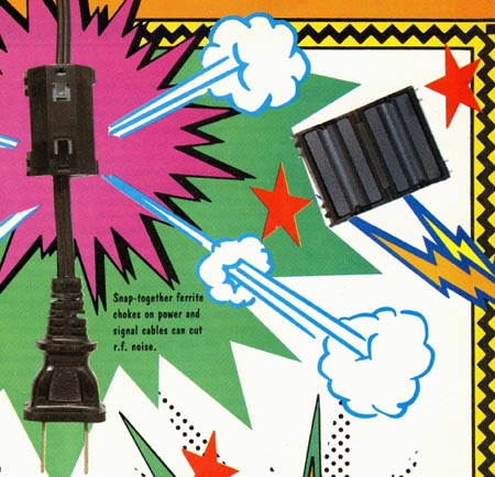
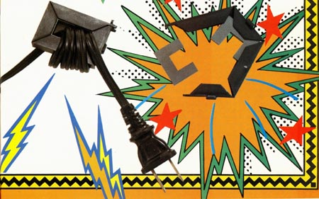
Above: Snap-together ferrite chokes on power and signal cables can cut
RF. noise.
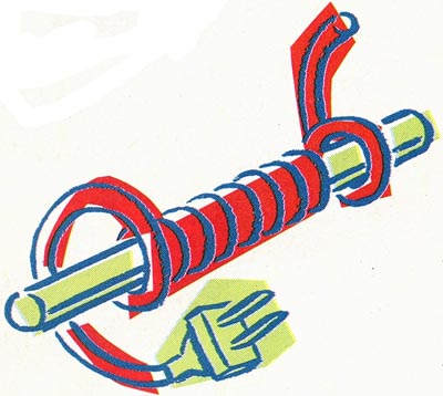
Above: A do-if-yourself toroid on a commercial ferrite core; the more
wire turns, the better.
There are several broad categories of radio-frequency interference encountered in audio equipment. Radio signals make their presence known in several ways. AM transmission is heard as voice or music. It may be very loud or slightly distorted.
Single-sideband (SSB) sources, including some GB transmissions, have the rhythm of speech, but their sound is garbled and indecipherable. Other forms of radio trans mission—such as FM, TV, Morse code, or digital data—are characterized by buzzing, clicking, or “tweedling,” which can be like constant or intermittent static. Electrical devices around the home can also intro duce noise. Motors produce constant static that can vary in intensity with motor speed; switches, thermostats, and other devices can cause single or intermittent clicks. Atmospheric disturbance produces uneven, crashing sounds. All of these can be treated by the same simple methods.
These electrical noises can get into your system in two ways. The first, direct radiation, is not common with modern, well- shielded equipment. In the unlikely event that direct radiation is your problem, mounting your equipment in a properly shielded case is the solution. The second way noise gets in is by conduction, through one of the wires that enters the equipment. Power cords, speaker wires, and interconnect cables are all possible culprits. Inexpensive interconnect cables, such as those supplied with most tape decks and other equipment, are often only partially shield ed, with wires that are spiral-wound about the cable’s inner dielectric.
Better quality cable uses a braided shield that completely covers the dielectric. It isn’t necessary to buy very expensive cable to eliminate r.f.i. The cables for a VCR’s/DVD player/satellite receiver/cable box's video signals are designed to carry radio frequencies and usually are properly shielded. Sometimes upgrading your cables, even in this modest way, will eliminate a noise problem. Yet even properly shielded cables can carry noise into an amplifier. It travels on the outside of the cable but still manages to get inside the amp via the input jacks. Shielded speaker cables and power lines are not generally available, anyway. You must use a filter.
Filters for the a.c. line are available from hardware stores, electronic supply houses, and Radio Shack (catalog No. 15-1111). Plug your equipment into one of these filters, and most noise from electrical appliances is eliminated. Radio Shack also sells various filters to keep noise from getting in via your FM antenna.
If the interference isn’t coming from the wall outlet but is radiating into the cords and cables, another kind of filter is needed:
A ferrite choke. Ferrite chokes are easy to make. They can be used on power cords, interconnects, or speaker cable. Ferrites come in several forms: Straight bars, rings or toroids, and tubes. You can wrap a cord or cable for five-to 20 turns around a ferrite bar. The old way was to get a ferrite bar from the antenna of an unused AM radio. A square toroid can be obtained from the flyback transformer of an old TV set. Leaving the high-voltage winding in place causes no harm, except to physically limit the number of turns of wire you can wrap about the core. While these homemade remedies often work, ferrites designed for the task of r.f.i. filtering are more likely to be effective.
Radio Shack sells two useful devices: A snap-together choke ferrite (No. 273-105) and a tordid choke (No. 273-104). The choke ferrite fastens together around an interconnect or a.c. line cord. (AudioQuest and TDK make similar devices.) The toroid choke is formed by wrapping the line cord, speaker leads, or interconnects about the toroid form—as many turns as will fit. The more turns, the greater the power of the choke to stop interference. More than one core can be used for tough cases.
Above: Another filter type: A power or signal lead wrapped around the
ferrite core from an old AM antenna.
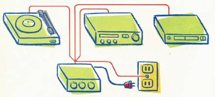
Above: To avoid ground loops, run all component grounds to a single
point, then try grounding that to the wall.
Put the ferrites as close to the input of the amplifying device as possible. In my case, I used ferrite toroids on the phono in put cable, as close to the preamp as I could (i.e., within an inch) and added a second set of toroids on the cable between the preamp and the amp, as close to the amplifier’s inputs as I could. This did the trick. No more cab drivers talking on my system!
Grounding your equipment also helps r.f.i. and hum problems. Three-prong power cords generally ground the chassis of a piece of gear. Many audio components have only two-prong power cords, which may be a good thing as far as noise goes. First, you need a good ground. Just because you have a three-prong outlet doesn’t mean the third prong is a ground, especially if you live in an older house. Test the ground status of your outlets, or have an electrician do it if you are not sure how.
The cover-plate screw on an AC outlet is another possible ground source. It's especially useful when your equipment has two-prong cords or when you have older wiring with two-hole receptacles. Again, test that the screw is, in fact, a ground. Water lines and radiator heat pipes are not always reliable grounds. If your amp or preamp is grounded through the power cord, fine. But only one piece of equipment should be grounded this way; otherwise ground loops may form, causing hum.
If there is no ground built into your equipment’s line cord, you can try grounding the chassis to the electrical ground at the cover-plate screw on the electric outlet. Usually the preamp (or the receiver, if you don’t have separate components) should be the one component grounded this way. Many preamps have posts around which you can wrap ground wires from the other components and the ground wire (if any) you’re running to the cover-plate screw. (Don’t make multiple ground connections to different parts of the preamp, or you’ll create another form of ground loop.) Experiment by listening to each component as you attach its ground to your preamp or receiver. If hum and noise improve, fine. If they get worse (a sign that the components affected are already grounded to the preamp through their audio interconnects, and your added ground just set up a ground loop), remove the ground.
In general, you want only one component grounded to earth, and the other components grounded to it. If you ground a component twice, the two paths to ground will never be the same length. This creates differences in electrical potential, setting up current loops that are audible as hum.
Some witchcraft is involved. In my old setup, the phonograph had to be grounded to the preamp or else it hummed. Same equipment, new location, and the phono couldn’t be grounded to the preamp or else it hummed. Sometimes, grounding your system to the wall outlet’s cover-plate screw makes noise worse, while other times it eliminates it. There are no definite rules, so you’ll have to experiment.
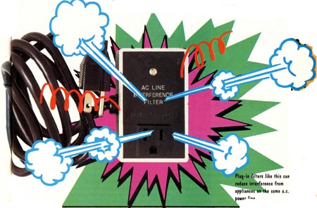
Above: Plug-in filters like this can reduce interference from appliances
on the same AC power line.