
By Phillip Windolph
1. Solid-state level-sensing switch for sump pumps
A FLOODED basement is a minor household disaster. That's why most homeowners whose basements are prone to flooding install sump pumps. Some, however, have discovered to their chagrin that the pump somehow fails to operate when it is most needed. In many instances of failure, the pump itself is actually in perfect working order. Rather, it is the water-detecting actuator switch that's the culprit, never sending a turn-on command to the pump.
Here's a simple, dependable circuit to replace the often-unreliable (usually mechanical) switch supplied as part of the pump assembly. It will automatically activate the pump when the water level reaches the level of a pump trigger probe. Once activated, the pump will remain energized until the water level falls below a keep-alive probe. If the pump fails or cannot keep the water in check, an optional alarm will sound as the water level reaches a trigger probe specifically for that purpose. The project can be powered either by batteries or the ac line. Inexpensive components are employed, most of which will be found in any well-stocked junk box.
About the Circuit. The Electronic Sump Pump Switch is shown schematically in the figure. Positive voltage from the power supply is applied to the COMMON probe via resistors R1 and R2.
(This and all other probes are stiff wires or metal rods suspended above and extending to different levels in the sump.)
As can be seen in the figure, the COMMON probe extends almost to the bottom of the sump. Any water entering the sump comes into contact with this probe, but as yet nothing which would cause activation of the pump happens.
As the water level in the sump rises, the KEEP-ALIVE probe touches the water, but this still does not activate the pump.
If the water reaches the level of the PUMP TRIGGER probe, current can flow from the positive supply voltage terminal through R1, R2, the water in the sump, R5 and finally into the base of 03. This transistor then turns on and provides base current for Q4. When Q4 conducts, t energizes the coil of relay K1.
Once this relay is energized, the normally open contacts are closed and two things happen. Line current is able to flow through the coil of K2, a heavy-duty ac relay. Also, the path between the KEEP-ALIVE probe and the base of Q3 is completed. Energizing K2 provides line voltage across SO/ for the pump. If the sump pump is connected to the socket, it will be activated and will start to pump the water out of the sump.
As the water level drops, the conductive path provided by the water in the sump between the COMMON and PUMP TRIGGER probes will be interrupted.
However, current will continue to reach the base of 03 via the KEEP-ALIVE probe, R7, and one set of contacts of relay K1. Because this probe extends almost to the bottom of the sump, relays K1 and K2 remain energized (as does the pump motor) until practically all of the water has been evacuated. When the water level drops below the free end of the KEEP-ALIVE probe, Q3 is deprived of base current and is cut off. This causes Q4 to stop conducting, deenergizing K1, K2 and the pump motor.
If the pump motor fails or cannot cope with the amount of water entering the sump, the water level will rise above the PUMP TRIGGER and KEEP ALIVE probes and eventually reach the ALARM TRIGGER probe. This probe is part of the optional alarm circuit and should be mount ed near the top of the sump. Although the alarm circuit is independent of the pump controller, it is a valuable addition to the project.
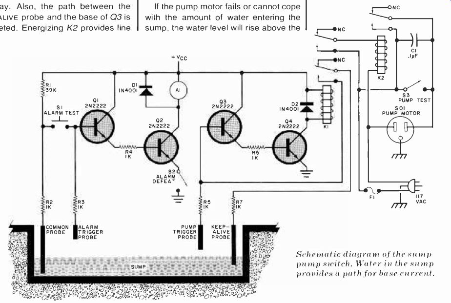
----- Schematic diagram of the sump pump switch. Water in the sump
provides a path for base current.
PARTS LIST
A1--DC-energized buzzer, bell, Sonalert or similar audible alarm*
C1--0.1-µF, 1000-volt disc ceramic
D1, D2-1N400I rectifier
F1--Fast-blow fuse *
K1--DC-energized relay*
K2--117-volt relay*
Q1 through Q4--2N2222 or similar npn switching transistor*
The following are 14-watt, 10% tolerance carbon-composition resistors:
R1--39.000 ohms*
R2 through R7-1000 ohms*
S1--Normally open pushbutton switch
S2-Miniature spst toggle switch
S3-Spst toggle switch*
S01--AC power socket
Misc Line-powered, regulated or battery do supply*; suitable enclosure; harrier terminal strip; perforated hoard; fuseholder; line cord; metal rods or stiff, solid-conductor wire; hookup wire; solder; self-tapping and machine hardware, etc.
*See text.
------------------
The alarm circuit closely resembles that of the pump controller and operates in a similar manner. Water reaching the ALARM TRIGGER probe provides a path for current to reach the base of Q1. This transistor begins to conduct and provides base drive for Q2. Transistor Q2 then conducts and completes the circuit for audible alarm A1, which alerts the homeowner to the fact that water in the sump has risen to a critically high level.
He can then try to get the pump working or, if necessary, bail the water out of the sump manually.
Two switches are associated with the alarm circuit and one switch is included in the pump controller. These switches provide test facilities for the alarm and pump (S1 and S3, respectively) and the ability to silence the alarm (S2). The currents handled by S1 and S2 are relatively small, so miniature components can be used in these locations. Switch S3, however, as well as the contacts of K2 must be capable of handling the current demanded by the pump motor, so use heavy-duty components.
The author employed a solenoid/ spring-type buzzer as his prototype's audible alarm. Diode D1 is connected across the buzzer to protect Q2 from inductive spikes generated by the buzzer.
Other types of alarms can be used, some of which will not require the inclusion of D1. A Sonalert or similar audio oscillator will not necessitate diode protection for Q2, but an alarm bell will.
Which type of audible alarm you choose is largely a matter of personal preference and parts availability. Similarly, there is a great deal of leeway in the choice of components Q1 through Q4 and R1 through R7. General-purpose 2N2222 transistors are suggested in the parts list. Just about any low-power npn transistor is suitable for use as Q1 and Q3. Exactly which transistor types are acceptable for use as Q2 and Q4 depends on the audible alarm and relay (K1) used. If the current demand of either load is fairly low, say, 300 mA or less, a general-purpose component such as type 2N2222 can be used as a relay or alarm driver.
However, if a load draws more than 300 mA, a higher-power driver will have to be used. A good rule of thumb is to use a transistor with a collector current rating that is double the current required by the alarm or relay coil. The author employed a sensitive 6-volt relay for K1 (Sigma No. 70R4T-6DC), which permitted the use of a low-power npn driver.
Diode D2 was included to protect the relay driver from inductive spikes.
The values specified for the fixed resistors (R1 through R7) are nominal ones. Substitutions can be made freely if you want to use components you have on hand. However, do not make the fixed resistances so low that they tax the base current ratings of the transistors employed in the project.
Either a line-powered or battery supply can be used for the project. The exact value of supply voltage is not critical and can be chosen to accommodate a particular dc relay (K1). Practical supply voltages range from 6 to 15 volts. Although it is not necessary, voltage regulation is desirable in a line-powered supply. The widespread availability of voltage regulator ICs makes the inclusion of regulation simple and inexpensive.
If the alarm circuit is included in the project, battery power enjoys a significant advantage over a line-powered supply-it will still provide power to the project if the commercial power line is blacked out. Of course, if line power is not available, the pump motor will not be activated, even though K1 will be energized. The alarm circuit, however, will be activated if the water in the sump rises to the level of the ALARM TRIGGER probe.
This will alert the homeowner that water is accumulating and had best be bailed out before any damage occurs. Also, when neither the alarm nor pump controller circuit is triggered, practically no current is drawn from the battery supply.
If non-rechargeable batteries are used to power the project, long operational life can be expected.
Construction. The circuit is relatively simple, which suggests the use of perforated board and point-to-point wiring techniques. Remote mounting of the alarm and pump controller circuits will simplify any future servicing. If this is done, the circuit board, relays, switches and power supply can be housed in a suitable enclosure which can be installed at some convenient location.
A four-terminal barrier strip can be mounted on the control box for the leads running to the sump probes. These probes can be fashioned from either metal rods or lengths of solid No. 12 or No. 14 copper wire and should be mounted rigidly above the sump. The probes are of varying length, with the COMMON probe extending almost to the bottom of the sump, the KEEP-ALIVE probe extending almost as deeply, the PUMP TRIGGER probe reaching about halfway down, and the ALARM TRIGGER probe extending only a short distance into the sump. Suitable lengths of hookup wire should be soldered to the probes and routed to the barrier terminal strip on the control box.
When constructing the control box, be sure to observe the polarities of all semiconductors and, if a line-powered supply is built in, of electrolytic capacitors. Use the minimum amount of solder and heat consistent with making good connections. Take special care in wiring the 117-volt ac portions of the project so that no shock hazard is present.
Checkout and Installation. After the control box has been wired, connect short lengths of hookup wire to the barrier terminal strip. Remove a portion of the insulation from the free end of each wire. Next, fill a drinking glass or measuring cup with water and place the wire connected to the COMMON probe terminal into the water. Place the wire connected to the KEEP-ALIVE probe terminal into the water. (Keep these and all probes from touching each other to realistically simulate actual operation. No damage will occur, however, if the probes accidentally come into contact.) Activation of the pump controller, indicated by a click as the relays are energized, should not yet happen.
Now insert the wire connected to the PUMP TRIGGER probe terminal into the water. You should hear a click as the relays are energized. If desired, a lamp can be connected to power socket SO1 and the line cord connected to the power line (assuming this has not yet been done). The lamp will then indicate that the relays are energized and that line power is reaching socket 501.
Remove the PUMP TRIGGER wire from the water. The relays should remain energized and no click should be heard.
Then remove the KEEP ALIVE wire from the water. At this time, the relays should drop out and a click heard. Finally, insert the ALARM TRIGGER wire into the water.
The alarm should sound and remain on until the wire is removed from the water.
Press the ALARM TEST pushbutton and keep it depressed. The alarm should sound and remain activated until the ALARM DEFEAT Switch is opened.
The operation of the PUMP TEST switch can be checked by closing it and observing whether the load connected to socket S01 receives line power.
Once it has been determined that the control box is functioning properly, a permanent installation can be made.
Mount the control box at some convenient point and interconnect it with the sump probes and pump motor. Be sure to bypass the stock pump-activating switch as it is no longer needed. As a final check, you can quickly fill the sump with water. The alarm should sound until the pump has lowered the water level beyond the reach of the ALARM TRIGGER probe. The pump should remain on until the KEEP ALIVE probe is no longer immersed, at which point nearly all of the water will have been taken out.
2. Vehicle low-fuel indicator
By Bradley Albing
------- Cable on author's prototype has connector for +12 volts, ground
and tank sender unit.
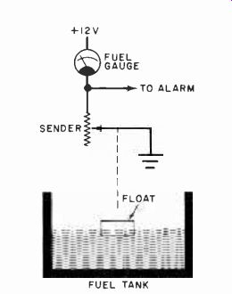
Fig. 1. Typical fuel-gauge circuit.
RUNNING out of gas can be an exasperating experience. The low-fuel indicator described here can help you avoid this situation. It will sound an alarm when the fuel level in your gas tank reaches a predetermined minimum. This level can be preset by a simple potentiometer adjustment.
Circuit Operation. In most vehicles, the fuel-level sensor is a float-controlled potentiometer (sender) wired in series with the dashboard-mounted fuel gauge (meter) and connected between the chassis and + 12-volt line as shown in Fig. 1. As the fuel level changes, the resistance changes, making the meter indication change.
The voltage level thus generated across the fuel-level sensor can be tapped off (at the meter) and, as shown in Fig. 2, applied through a low-pass filter R8-C4 so that the voltage across C4 is the average across the sender. This low-pass filter also eliminates any rapid voltage fluctuations due to gasoline sloshing and a bouncing sensor float, or voltage transients generated by the switching voltage regulator as used in some vehicles.

Fig. 2. Comparator IC1 turns on when fuel drops below some predetermined
level, and sounds the alarm. The SCR circuit energizes a flashing LED
during the Cancel mode.
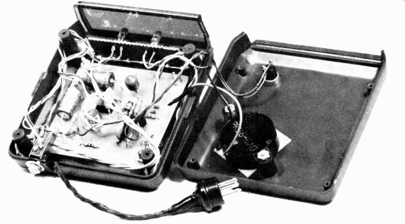
------- PC board mounted in prototype with alarm and CANCEL switch
on top.
----------
PARTS LIST
A1--Sonalert, buzzer or other 12-volt alarm (Radio Shack 273-060 or similar)
C1,C2--100-µF, 25-V aluminum electrolytic
C3, C5--0.1-µF. 25-V disc or Mylar
C4--300-µF, I 5-V tantalum electrolytic
D1,D7,D8--1N914
D2--1N5742, 18-V, 400-mW zener
D3,D4,D9--1N751A, 5.1-V, 400-mW zener
D5--1N42811 D6-IN5732, 6.8-V, 400-mW zener
IC1 3140E op amp
LED 1 red LED LED2-Litronix FRL-4403 flashing LED (Radio Shack 276-036)
Q1--2N3053 or similar
Q2--2N3904 or similar
The following are 1/2-watt. 10% tol. resistors.
R1, R11-100 ohms
R2-33 ohms
R3, R5, R12-470 ohms
R6-10 megohms
R7-470,000 ohms
R8-33.000 ohms
R9-330 ohms
R10--10.000 ohms
R13--820 ohms
R14--2(X)ohms
R4--25,000 ohm potentiometer
SCR1--2N5062
S1-normally open pushbutton switch
Misc.-Suitable enclosure (Radio Shack 270-285 or similar), interconnecting leads, mounting hardware
Note: The following are available from BFA Electronics, P.O. Box 212, Northfield, OH 44067: No. LF-2 pc board for $4.50 + $1 p&h; No. LF-2-KIT all parts in Fig. 2 except case and connector for $18 + $2 p&h. Ohio residents, please add sales tax.
------------
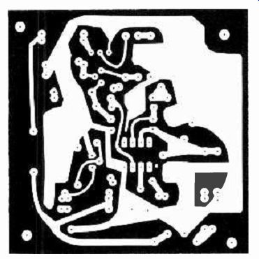
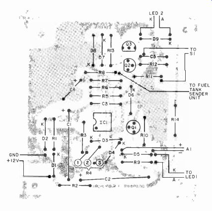
Fig. 3. Actual-size etching and drilling guide is shown at left. Component
placement guide is above.
The C4 voltage is applied to the non-inverting (+) input of comparator IC1, and rises with decreasing fuel in the tank. When this voltage exceeds the R4 preset voltage on the inverting (-) input, the output of IC1 (pin 6) goes high.
This voltage (approximately 9 volts) is high enough to cause zener diode D6 to conduct and turn on transistor Q1. When turned on, this transistor draws current through audible alarm A1, and turns on optional indicator LED 1.
As long as the fuel level is low, the output of IC1 remains high. To silence the alarm until the tank is filled, CANCEL switch S1 is depressed to trigger SCR1.
When triggered, the SCR brings the junction of R5-D6 (the input to Q1) down to approximately 2.2 volts, which is not high enough to cause D6 to conduct and activate the alarm circuit. Since the SCR is powered by dc, it will remain turned on as long as the IC1 output is high (the fuel level is low). As long as SCR1 is conducting, there will be about 1.2 volts (two diode drops) across D7 and D8, enough to turn on Q2 and cause LED2 to operate. This LED is a special type that incorporates a built-in flasher circuit that makes the LED flash at a 2.5-Hz rate as long as the LED is powered. The maximum voltage permitted across this special LED is 6 volts, hence the presence of 5.1-volt zener diode D9.
The incoming dc power line is noise decoupled by R1, C1 and C3. Zener diode D2 clamps any transients to a maximum of 18 volts while diode D1 makes sure that the correct polarity is supplied to IC1. Filter R2-C2 decouples the power line to the alarm and indicator circuit.
Diode D5 clamps any voltage spikes that may occur if an inductive load, such as a buzzer, is used as the alarm. Resistor R6, connected between the output of IC1 (pin 6) and the noninverting (+) input, adds a small amount of positive feedback to give the comparator a little hysteresis and speed up the transition from low to high. This also reduces the likelihood of comparator oscillation.
Construction. The circuit may be constructed on pert board, Wire-Wrapped, or on a pc board such as that shown in Fig. 3 along with the component installation.
The two LED indicators, CANCEL switch S1, level-select potentiometer R4, and the selected audible alarm are not mounted on the pc board.
The finished pc board can be mounted within a selected enclosure that will also mount the off-board components.
Power can be derived from any +12-volt source that becomes active when the vehicle ignition key is operated. The ground can be any convenient metal element that is solidly connected to the vehicle chassis.
You will have to locate the dashboard end of the fuel sensor lead. Test this lead by measuring the voltage across it with various levels of fuel. Usually, the lower the fuel level, the higher the voltage. It is possible for this voltage to vary due to the action of the vehicle switching voltage regulator (if your vehicle uses one) so this must be considered.
If you have any doubt as to the type and wiring of the fuel-level sensor in your vehicle, consult the vehicle repair manual.
Calibration. There are two ways to calibrate the system. The first is to wait until the fuel level is down to the selected low level, then adjust R4 until the alarm sounds off.
The second approach is to disconnect the fuel gauge from its feed line to the fuel sender but leave the lead connected to the low-fuel alarm, then connect a resistor-substitution box between the fuel gauge and ground (as a substitute for the fuel sender). Adjust the value of the resistor until the fuel gauge indicates the desired level. Adjust R4 to sound the alarm at that point. Disconnect the resistor box and replace the fuel sender line.
Once the fuel-level turn-on point has been determined, depress S1 to silence the alarm. After the tank is filled, the alarm will be reset until the fuel level drops below the predetermined point.
-----------------------
3. Portable gas leak meter
TOXIC and explosive gases are an ever-present danger in our modern society. They include natural gas, propane, fuel vapors, and invisible and odorless carbon monoxide.
The ultra-sensitive gas-leak detector presented here indicates the quantitative presence of these gases and enables one to track down and pinpoint the source of a gas leak by observing the unit's meter indication. Moreover, it is a portable, battery-powered model for use in boats, cars at campsites, etc.
Circuit Operation. The gas sensor, GS1 in Fig. 1, consists of an electrically heated tin-oxide pellet that changes resistance when exposed to carbon monoxide, hydrogen, propane, alcohol, gasoline vapor, and other oxygen--reducing gases. Power for the circuit can be obtained from either six D cells, preferably rechargeable, connected in series or from an optional 9-volt battery eliminator. Regulator IC1 reduces the available 9-volt level to the 5 volts required by the circuit. Optional LED1 is a Current from the regulator heats gas sensor GS l's semiconductor pellet. The sensor, R4, R7, and R8 are arranged in a bridge configuration. The null indicator consists of M1 and R6, while D1 and D2 serve as protection for M1. Overall circuit sensitivity is determined by the value of resistor R5, while S2 provides a BATT. TEST function.
Once the bridge is balanced, by NULL potentiometer R8, any change in the resistance of GS1 will create an unbalanced condition. When this occurs, the meter's pointer swings upscale, by an amount proportional to the change in resistance of GS1.
==========
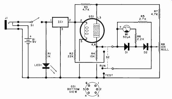
Fig. 1. The gas sensor forms one arm of a Wheatstone bridge.
Pins 1, 2 and 3 can be interchanged with pins 4, 5 and 6.
Once bridge is balanced by R8, a change in resistance of GS1 will cause meter pointer to swing upscale.
PARTS LIST
B1--Six D cells in series
D1, D2-Germanium diode ( IN34A or similar)
GS I-Model 812 gas sensor
IC1--5-volt regulator (Radio Shack No. 276-1770 or similar)
I1--Normally closed miniature phone jack (Radio Shack No. 274-281 or similar)
LED 1--Red light emitting diode MI-50-µA meter (Radio Shack No. 22-051. No substitute)
R1--10(X)-ohm, 1/2-W, 10% resistor R2-22,(X)0-ohm, 1/2-W, 10% resistor
R3,R7-4700-ohm, 1/4-W, 10% resistor
R4--15.000-ohm, 1/4-W, 10% resistor
R5--2700-ohm. ¼-W. 10% resistor
R6--2200-ohm. 1/2-W, 10% resistor
R8--10,0(X)-ohm linear potentiometer
S1--Spst switch
S2--Dpdt switch
Misc.-7-pin miniature tube socket; battery holder: enclosure; 9-volt dc calculator-type ac adapter (optional); machine hardware; hookup wire; solder: etc.
Available for $10.00 postpaid from Southwest Technical Products Dept., PE-2, 219 W. Rhapsody, San Antonio, TX 78216.
=========
Construction. With the exception of GS1, J1, M1, B1, R8, S1, and S2, the circuit can be assembled on a piece of perforated board. Select an enclosure large enough to accommodate the board and all off-board components, including B1 and its holder.
Mount the meter movement on one side of the enclosure's front panel, the remaining off-board components (except B1 and J1) on the other side of the panel. The battery holder and optional battery-eliminator/charger jack J1 are best mounted on the rear wall of the ener, set S1 to ON and S2 to BATT. TEST, and make a note of the point on the meter's scale at which the pointer comes to rest. Turn off the power and carefully remove the cover from the meter's face.
Use a felt marker to identify the battery--test point on the meter's scale.
S2 to RUN and, in a neutral atmosphere, adjust NULL control R8 until the meter indicates zero. Now, place a drop of alcohol or gasoline on a finger and approach the sensor. The meter pointer should swing up-scale. Move the finger away from the sensor: it will take a min--closure. If desired, GS1 can be mounted either directly on the front panel or in a separate housing, the latter fitted with a cable to connect it to the main enclosure. The sensor itself takes a miniature 7-pin tube socket.
After the project is assembled, install a fresh set of D cells in the battery hold--Operation. Set S1 to ON and allow the sensor to heat up for about two minutes.
Set S2 to BATT. TEST and check that sufficient voltage is available from the battery. (A set of fresh D cells will last about 20 hours. An external 9-volt battery-eliminator/charger can be used.) After the sensor has warmed up, set ute or so for the sensor to settle back for the next measurement. Readjustment of R8 may be necessary occasionally. If setting time is too long, change R7 to 1000 ohms.
When looking for a gas leak, note locations where the meter swings upscale to narrow down the location.
------------------------
4. Electronic pedometer for joggers
By Andrew A. Modla
AN INEXPENSIVE pocket calculator can be converted to operate as an electronic pedometer to keep an ongoing tally of the number of steps taken while walking and jogging. Then, with a simple conversion, you can use the calculator to determine the number of yards, meters, miles, or kilometers travelled. Although the conversion described here is "hard wired" into the calculator, you sacrifice none of the calculator's basic built-in capability.
Calculator Conversion. The first thing you must do is determine whether or not your calculator has a built-in constant function. To do this, press CLEAR, 1, +, 1, =, =. If your calculator has the necessary constant function, the display should read 3 and should increment by 1 for each additional operation of the = key. Having established the fact that your calculator does indeed have the constant function, you can proceed with the conversion.
Conversion of the calculator consists in simply wiring a foot-operated switch across the = key. First, carefully open the calculator's case and locate the contacts for the = key. Then solder a 5' (1.5-meter) or so length of 26-gauge flexible stranded wire to each = switch contact. Insulate the soldered connections with a layer of electrical tape.
Now, test your hookups in the following manner. Turn on the calculator and key in 1, +, 1. Touch together and separate the free ends of the wires two times.
With the first touch, the display should read 2 and with the second, 3. If the test checks out properly, turn off the calculator and reassemble it, routing the wires out through the side of the case. If necessary, use a sharp knife to cut a slot to allow the wires to exit the case. No other modification is necessary . Footswitch Fabrication. As shown in the drawing, the footswitch is fabricated from a commercially available "air--pillow" foam insole. Begin by cutting a 1" (25.4-cm) square away from the center of the heel area of the insole. Cement a square of copper-coated Mylar or any other flexible conductive material over the cutout on both sides of the insole, conductive surfaces face-to-face.

--------- Place copper foil on each side of insole hole and
insulate with tape.
Solder the free ends of the flexible wires from the calculator to the conductive material. Then cover the "switch" assembly with duct or other durable tape to keep out dirt and moisture.
Slide the insole into your shoe and put on the shoe. Turn on the calculator and key in 1, +, 1. Now, as you walk around, the display should read 2, then 3, then 4, etc., as you successively put weight on the switch shoe with each step. If you do not obtain these results, turn off the calculator and carefully check out the switch arrangement.
Determining Distance. Every time you use the pedometer, you must first key in 1, +, 1. Thereafter, the calculator increments the display by 1 for each step taken by the shoe in which the switch is installed. To determine how far you have run or walked, you must find out how many steps you take in a given measured distance (mile, kilometer, etc.). You must, therefore, measure off the "control" distance and walk or run it to determine how many steps are required to cover the course.
Let us assume you wish to know how many miles you have walked and have previously determined that it takes you 1056 steps to walk a mile. (Note that a step is two strides. If the switch is in your right shoe, a step is completed every time you set down your right foot.) Now, subtract 1 from the total displayed by the calculator. This is necessary because the first step you take will register 2. If we assume you stopped at 7200 steps, simply divide this number by 1056, your "control" number, using the calculator to obtain the number of miles walked.
Therefore, 7200/1056 = 6.82 miles.
[ P-E Exp. 1982]
Also see:
Link | --Link | --Build the Audio Detective