BY DENNIS BOHN
AN INCREASING number of audiophiles are incorporating graphic equalizers into their hi-fi music systems. The new component is most often used as a "super" tone control that offers a degree of frequency response compensation beyond the capabilities of bass and treble controls. However, adjusting 10 to 30 controls to compensate for acoustic deficiencies in the listening room can be challenging. This project--a pink noise generator-makes the job a little easier. It provides a reference signal for performing equalizer adjustments, and uses just one IC and a few passive components.
The IC, National's MM5837 or AMI's S2688, is a digital pseudo-random sequence generator which will produce a broadband white noise signal for audio applications that's converted to pink noise by a passive filter. Unlike traditional semiconductor junction noise sources, these ICs provide uniform noise quality and output amplitude.
White vs. Pink Noise. The output of the MM5837 is broadband white noise. Since pink noise is used in most audio work, it is helpful to understand the difference between the two.
White noise is a composite signal with contributions from all frequencies and a spectral density substantially independent of frequency (equal energy per constant bandwidth). It is characterized by a 3-dB increase in amplitude per octave of frequency change. In comparison, pink noise has a flat amplitude response per octave of frequency (equal energy per octave). Pink noise allows correlation between successive octave equalizer stages by insuring that the same amplitude of input signal is used for each as a reference.
The network required to convert white noise to pink noise is simply a -3-dB/ octave low-pass filter; but it presents an interesting problem in circuit design. If capacitive reactance (and thus the response of a simple RC or first-order filter) varies at a rate of -6 dB/octave, how can a slope of less than -6 dB/ octave be obtained? The solution lies in cascading several stages of lag compensation so that the zeros of one stage partially cancel the poles of the next stage. Such a network, shown in Fig. 1, has a -3-dB/octave characteristic (± 1/4 dB) from 10 to 40,000 Hz.
The complete pink noise generator in Fig. 2 gives a flat spectral distribution (per octave) over the audio band from 20 to 20,000 Hz. An 11.5-V p-p random pulse train appears at pin 3 of the IC, and is attenuated by the filter. The actual output across C5 is about 1 V p-p ac of pink noise riding on an 8.5-V dc level.
Construction. Since the circuit is fairly simple, it can be constructed on a small circuit board using printed circuit, point-to-point wiring, or Wire-Wrap techniques. Resistors in the filter network should have close tolerances. Premium-grade tantalum and polystyrene, ceramic, and film capacitors are recommended. Observe standard precautions in handling the MOS device, and use an IC socket or Molex Soldercons.
PARTS LIST
C1-1-µF, 35-V metallized polyester
C2--0.27-µF, 35-V metallized polyester
C3--0.047-µF metallized polyester
C4-0.033-µF metallized polyester
C5-10µF, 16-V electrolytic
C6-100-µF, 35-V electrolytic capacitor
IC4-MM5837 noise generator IC
R1-6800-ohm, 1/4-W, 5% resistor
R2-3000-ohm, ¼-W, 5% resistor
R3--1000-ohm, 1/4-W, 5% resistor
R4--300-ohm, 1/4-W, 5% resistor
Misc.-Circuit board, 15-volt regulated supply, output jack, output connector, IC socket or Molex Soldercons, hookup wire, solder, suitable enclosure, etc.
KIT AVAILABILITY
A complete kit of parts, including an MM5837 or S2688 IC and plated etched and drilled pc board but less miscellaneous items is available as Kit PN-1 for $14.95 from TOLECO Systems, P.O. Box 401, Kingston, WA 98346. Washington State residents, please add 5.3% sales tax.
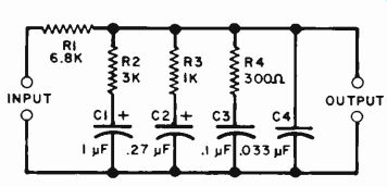
Fig. 1. Low-pass filter with -3-dB/octave response.
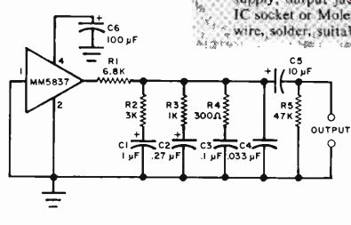
Fig. 2. Schematic diagram of the pink noise generator.
Source: (Popular Electronics Electronic Experimenter's Handbook (1982)
Also see:
Precision References for Current & Voltage
Listen To A New World Of Sounds With Ultrasonic Detector