AMAZON multi-meters discounts AMAZON oscilloscope discounts
INTRODUCTION
Electricity seems so elusive, so mysterious. We know it is used to operate most of the equipment around the home and the office. Home lighting, appliances, heating and air conditioning, televisions, stereos, workshop tools, video games and home computers depend upon electricity for their operation. Although we can see and feel the effects of electricity, it would benefit one a great deal to understand the effects if one could measure it. That is the purpose of meters -- voltmeters, ammeters and ohmmeters. They measure basic electrical quantities such as voltage, current and resistance.
This guide has been written to help you understand how such meters work and how they can be used to make basic electrical measurements - in the home, in the workshop, at the office, on the job.
There are two basic types of meters used to make electrical measurements. One type has a needle that deflects along a scale and indicates the value of a quantity by the position of the needle on the scale. This is an analog meter, and is commonly called a voltmeter, ammeter, ohmmeter, VOM, multimeter or multitester depending on the quantities that it measures. The meter mechanism is generally of the D'Arsonval type which will be detailed later.
Figure 1-1 shows a typical analog meter. The main meter parts are the meter movement (behind the scales) that contains the needle that deflects to the right along a scale, the switches that select which quantity the meter is set to measure and the full-scale range of the meter for the measurement, and several adjusting controls and jacks that accept plug-in test leads used to connect the meter to a component or circuit for measurement.
The other type is a digital meter. Any quantity that is measured appears as a number on a digital display. It is commonly called a digital voltmeter, DVM, digital multimeter or digital multitester.
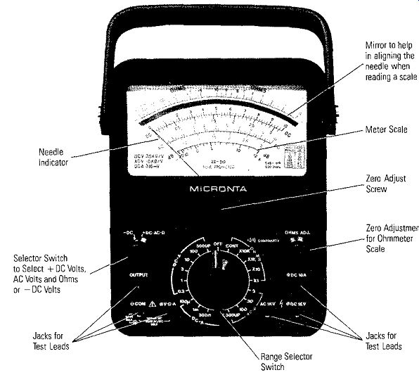
Figure 1-1. Analog Meter: Selector Switch to Select + DC Volts, AC Volts and
Ohms or -DC Volts Jacks for Test Leads Range Selector Switch Mirror to help
in aligning the needle when reading a scale Meter Scale Zero Adjust Screw
Zero Adjustment for Ohmmeter Scale Jacks for Test Leads
A typical digital meter is shown in Figure 1-2. The digital display is the main meter output, indicating the numerical value of the measurement. A range selector switch or switches not only selects the type measurement, but the full-scale range of the measurement as well. Jacks accept the plug-in test leads, and the ON-OFF switch applies battery power to the internal circuits when in the ON position. A set of test leads are shown in Figure 1-3.
Let's look at the most common type meter first-the analog VOM (Volt-Ohm Milliammeter).
THE BASIC METER MOVEMENT
The VOM, with its needle that moves on a scale, is basically a small electrical motor.
To understand electrical motor action it is necessary to understand two very simple electrical principles: 1. What happens when there is current in a wire or other type conductor of electricity, and 2. magnetism and magnetic fields. Let's take magnetism first.
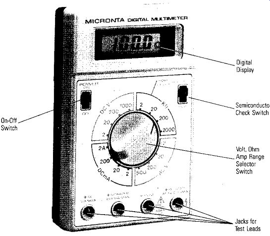
Figure 1-2. Digital Meter On-Off Switch

Figure 1-3. Test Leads; Test lead
Probes; Plugs That Fit into Meter Jacks
Figure 1-4 shows a coil of wire with many turns mounted on a pivot between the north and south poles of a magnet. There is a magnetic field running from the north pole to the south pole. The field is invisible, but if it were visible, it would appear as lines starting at the north pole and stopping at the south pole, as shown in Figure 1-4.
The field lines leave and enter the magnet's surface perpendicular (at right angles) to the surface. The pole pieces have a special shape so that the magnetic field is very uniform throughout the air gap between the pole pieces and the meter movement coil. The purpose of such a uniform field between pole pieces will not be apparent until we look at the second simple principle of motor action - current in a wire or conductor.
Current in a Wire
A Danish physicist, Hans Christian Oersted, in 1819, discovered that a magnetic field surrounds a wire or conductor in which there is current. The effect is shown in Figure 1-5. A current in the wire in the direction shown will produce a magnetic field counter-clockwise around the wire as shown - the larger the current, the larger the magnetic field. In this guide those of you that are familiar with electron current use the dotted line directions for current, and those familiar with conventional current use the solid line directions.
Figure 1-6 is a cross section through the pole pieces and one loop of the coil of wire shown in Figure 1-4. It shows the motor action. As an example, let's look at leg A of the loop of wire in Figure 1-6. Electron current is out of the page; therefore, the magnetic field produced is clockwise around the wire. At the top of leg A, the current magnetic field adds to the uniform magnetic field; at the bottom of the leg A it subtracts. As a result, a force is developed that pushes on the loop of wire and causes it to rotate. The stronger magnetic field at the top forces the leg A of the loop down.
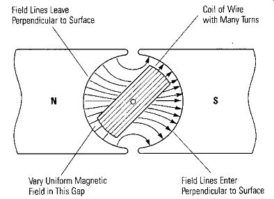
Figure 1-4. Meter Coil in Magnetic Field Between Pole Pieces of Magnet
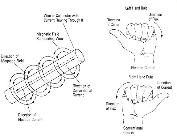
Figure 1-5.
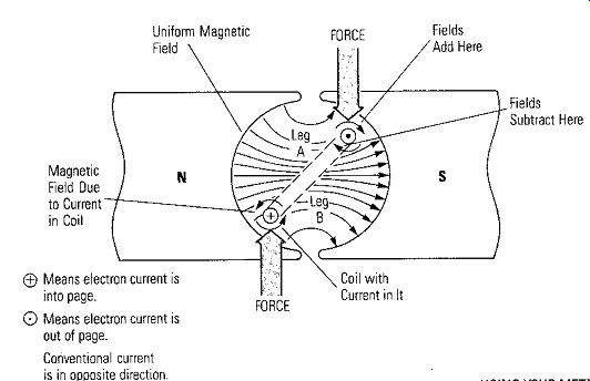
Figure 1-6
The continuous current in the loop goes into the page in leg B. The current magnetic field now is in a direction to force leg B up as shown, thus aiding the force on leg A to cause the loop of wire to rotate clockwise. This simple explanation is the basis for all electrical motor action, and the basis for the meter movements of the analog meter we will be discussing.
Operation of the Basic Meter Movement
Let's look further at the basic construction and operation of the analog type meter called a D'Arsonval meter (Figure 1-7). The movable coil with many turns, called an armature, has a needle attached to it, and is located within the strong magnetic field of the permanent magnet (PM) which is hidden under the scale plate . The uniform radial field about the moving coil is required to make the torque produced by the current in the coil result in a linear movement of the meter needle along the calibrated scale. As current increases, the deflection increases.
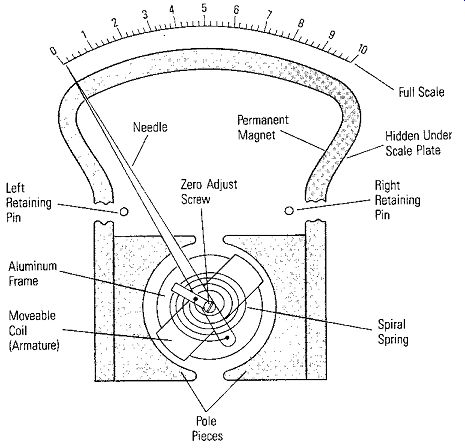
Figure 1-7. D'Arsonval Moving Coil Meter Movement
One end of the needle is attached to a spiral spring so the needle will be returned to an initial position when the current in the coil is removed. The springs are calibrated and the coil and needle are balanced so that the total assembly produces a linear deflection on the meter scale as the current in the coil is increased linearly.
The other end of the spiral spring is attached to a ZERO ADJUST screw located on the core of the moving coil. With the ZERO ADJUST, the initial static position of the meter movement is adjusted mechanically to zero on the scale by varying the position of the end of the spiral spring. Care must be taken in making this adjustment because of the delicate construction of the spiral spring.
The complete needle assembly usually is constructed around an aluminum frame so that the assembly is very sturdy. The aluminum frame also serves a purpose for damping, which will be discussed a bit later.
Since the radial magnetic field is produced by a permanent magnet, the direction of the force of this field is always in one direction. Thus, the current must pass through the coil in one direction only to cause an upscale deflection on the needle. If current passes through the meter movement coil in the other direction, the needle deflects backwards against the meter's left retaining pin. This is one of the most common ways of damaging or burning out a meter -- passing too much current through the coil in the wrong direction.
Damping
To prevent overshoot when the meter coil and needle assembly moves, it must be damped. As mentioned, the aluminum frame accomplishes the damping. It is effectively a short circuited single turn loop within the meter's magnetic field. A loop of wire moving in a magnetic field will have a voltage induced in the loop. Any movement of the meter armature moves the frame, and the induced voltage causes a current in the frame. As with any current in a conductor, the frame current develops a magnetic field which interacts with the strong magnetic field of the permanent magnet and offers a slight opposition to the movement of the coil. This method of damping the moving coil movement is an application of a law developed by Heinrich Lenz, a German physicist. The law states that the resultant current in a wire moving in a magnetic field produces a magnetic field that opposes the original magnetic field that generates the voltage that produced the current.
BASIC CHARACTERISTICS
Meter Movement Sensitivity
The sensitivity of the meter movement depends upon the current required for full scale deflection. It varies inversely with the current; that is, the most sensitive meter requires the least current for full-scale deflection. The amount of current required to deflect the needle full scale depends upon the number of turns of wire on the moving coil. When more turns are added, usually by using smaller and smaller wire, a stronger magnetic field is created to react with the permanent magnetic field.
Smaller wire also keeps the mass of the meter movement low.
• Measuring Sensitivity
The sensitivity of a meter can be determined by measuring the current required to produce full-scale deflection. To do this, a standard current meter is placed in series with the unknown meter and a source of current applied to the meter as shown in Figure 1-8. Since the current is the same in all parts of a series circuit, the amount of current to produce full-scale deflection on the unknown meter can be read directly from the standard meter. Meter sensitivities range from a few microamperes for very sensitive movements to 50 to 1,000 microamperes for average movements used for multitesters that measure voltage, current and resistance.
Internal Resistance
The meter sensitivity and the internal de resistance of a meter movement are fixed by the design; definite characteristics that cannot be altered unless the physical construction of the meter movement is changed. To measure a meter's internal resistance, with the full-scale current through a meter indicated by the standard current meter, a voltmeter is connected across the unknown meter to measure the voltage drop across its internal resistance. The meter's internal resistance may then be obtained by Ohm's law: V=IR
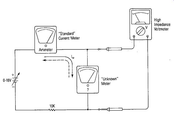
Figure 1-8. Measuring a Meter's Sensitivity and Internal Resistance
... where V_M is the voltage across the meter and IM is the current through it for a full scale reading. A meter that is designed to have full-scale deflection with a very low current will have high sensitivity and high internal resistance.
CAUTION: A sensitive meter movement can be easily destroyed by connecting an ohmmeter across it in an attempt to measure its internal resistance. The ohmmeter has an internal battery and can supply current. The current from the ohmmeter may be 100 times that required to deflect the meter full scale.
Meter Accuracy
There are many factors that affect a meter's accuracy: the design of the meter, the quality of its parts, the care in its manufacture, the accuracy of its calibration, the environment it is used in, and the care it has had since being put into service.
The accuracy of a meter that is used in everyday applications (not under controlled environmental conditions) is usually between 0.01% and 3%. The accuracy of meters that have D'Arsonval movements (Figure 1-7) that are commonly used in all types of measuring instruments is about 1% of the full-scale reading. If a voltmeter has a 10 volt scale and it has a 1 % accuracy, any reading is going to be accurate to ± 0.1 volt. The stated accuracy of the meter in percent refers to the percent of full scale reading on any range.
Let's look at Figure 1-9. The accuracy of a voltage reading for a meter that has a stated accuracy of 1% is plotted against the voltage to be read for three full-scale ranges -10 volt, 5 volt, and 2. 5 volt. If a voltage of 2 volts is measured, it will be accurate to ± 0.1 V (5%) if measured on the 10 volt range, ± 0.05V (2.5%) if measured on the 5 volt range, and ± 0. 025V (1.25%) if measured on the 2. 5 volt range.
As a result, a meter reading taken at the low end of the scale is going to have a greater percent of absolute error than a reading near full scale. Thus, to have the greatest accuracy, it is best when making measurements to chose the range for the meter so that the deflection is nearest to full scale. The closer the reading of the meter to full scale, the less the absolute error.
AMMETERS
The simplest ammeter contains only the basic meter movement. It can measure values of current up to its sensitivity rating (full-scale deflection). Meter movements that require a large current for full-scale deflection are not practical because of the large wire they would require on the coil, and thus, the large mass. Therefore, highly sensitive meter movements are desensitized by placing low value resistors called "shunts" in parallel with the meter movement to extend their current handling range.
If a meter movement requires 100 microamperes for full-scale deflection and the meter is to have a 10 milliampere (10,000 microamperes) scale, a shunt across the meter must have a resistance value to carry 9900 microamperes.
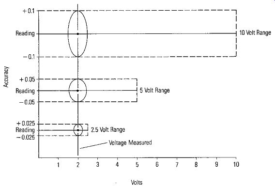
Figure 1-9. Accuracy Range of 1% Meter on Various Full-Scale Ranges
Simple Ammeters
Figure 1-10 shows a single shunt across a basic meter movement to extend the range of the movement. Shunts are easily calculated by applying Ohm's Law (V = IR) and the principles of a parallel circuit, if the meter movement's internal resistance RM is known. The derivation of the equation for the ammeter shunt resistor Rs is as follows: The voltage across the shunt, Vs, is equal to the voltage across the meter V M• Therefore, Vs= VM Vs is equal to the current through the shunt, I,, times the shunt resistance, R,. VM is equal to the current through the meter movement, IM, times the meter resistance, RM.
Therefore, lsXRs=l:v1xRM
Solving for R, gives, R - (IM X R,J s – Is
Substituting IT - IM for ls gives, Rs = (IM X R,J (IT - IM)
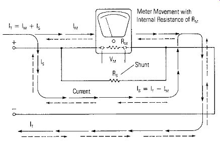
Figure 1-10. Using a Single Shunt to Extend the Range of a Basic Meter Movement
The use of this meter shunt equation will provide the correct value of resistance to be added in parallel with the meter movement to increase the current handling capability of the meter.
Example: If IM = 1 milliampere, RM = 1000 ohms and IT is to be a full-scale range of 1 ampere, then the shunt resistance is: R
_ 0. 00IA x 1000 ohms s - (1,000-1)mA 1V Rs= 999mA 1 Rs= 0.999A Rs = 1.001 ohms
Multirange Ammeters
• Simple Shunts
What we have said is that a basic meter movement has a given sensitivity -- a given amount of current must pass through it to produce full-scale deflection. By using suitable shunts, the range of current that a given movement can measure is increased. This is essentially the process used in the construction of multirange ammeters. In Figure 1-11, a four-range ammeter is shown. The meter leads are used to connect the meter in the circuit to measure a current. Note the lowest range (position 1) uses the meter's basic sensitivity of 1 milliampere (1 mA) with no shunt.
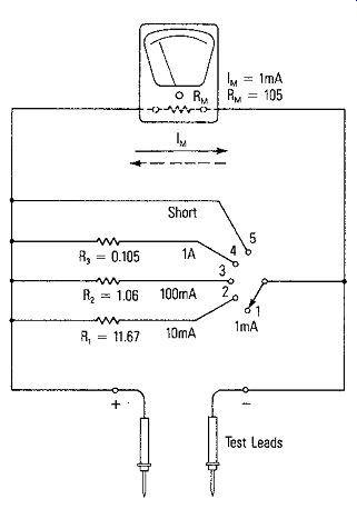
Figure 1-11.
A Multi-Range Ammeter
The values of the shunts are given. These values may be verified using the equation for Rs just discussed. The fifth position on the switch is marked SHORT which takes the meter out of the circuit without physically disconnecting its leads.
• Ring Shunts
Another type of shunt commonly used in multimeters or multitesters is shown in Figure 1-12. It is called a ring-type shunt or Ayrton "universal'' shunt. In the circuit, the resistors, R,. R,, R,, R5 and Re. are used as shunts. They are all connected in series and, in turn, are connected in parallel across R, and the basic meter movement. R, is always in series with the meter movement.
The position of the switch, S,, determines which of the resistors R, through R, also are placed in series with the basic meter movement. The remaining resistors form the shunt to increase the current range. The resistance needed for each current range is calculated in the same way as in the simple shunt circuit, except that the resistance in series with the meter is added to RM.
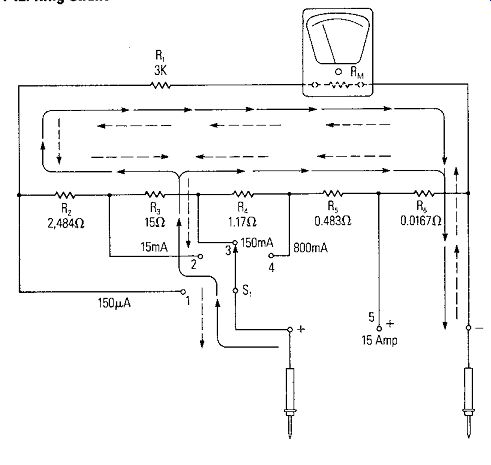
Figure 1-12. Ring Shunt
For example, S, in Figure 1-12, is in position 3, the 150 milliampere (150 mA) scale. For this lull-scale value, series resistors R" Re, and R, are in shunt with the total series resistance represented by R,, R,, R, and the internal resistance of the meter, RM. Because of the number of unknowns in this circuit, it is impossible to use the previous equation for calculating Rs- Rather, an equation based upon Ohm's law and the laws for parallel circuits can be derived, We will not derive the equation, because of the length of the derivation, but just offer the equation for use. It is R _ (Rsum X IM) s - IT where Rs equals the total value of the shunt, Rsum equals the sum of the resistances in the ring of the ring-type shunt, IM equals the maximum current through the meter movement (its sensitivity), IT equals the new full-scale value of the current. In Figure 1-12, Rsum would be equal to R, + R, + R, + R, + Rs + R,. The ring type shunt eliminates the problem of high contact resistance which can cause errors in the simple shunt meters. It also eliminates the need of a special type of make-before-break type switch on the range switch of the ammeter of Figure 1-11.
The make-before-break switch protects the basic movement from high currents as the selector switch of Figure 1-11 is switched to different ranges. Examining the circuit will show that full measured current could pass through the basic movement if the selector switch opens the shunt circuit on switching.
BASIC VOLTMETERS
Using Ohm's law (V = IR) again, where V is the voltage applied, I is the circuit current and R is the total circuit resistance, the product of the meter movement's sensitivity, IM, and the meter movement internal resistance, RM, equals the voltage across the meter movement, V ,,,, for full-scale deflection. When additional series resistance is added, it converts the basic meter movement into a direct current (dc) voltmeter. The series resistor is called a multiplier. The basic circuit is shown in Figure 1-13. The value of the multiplier resistor, Rx, determines the voltage range for full-scale deflection. By changing the value of the multiplier resistor, the full-scale voltage range can be changed.
Multiplier Resistance
The value of the multiplier may be found by using Ohm's Law and the rules of a series circuit. Let's look again at Figure 1-13. Since the multiplier resistor, Rx, is in series with the basic meter movement, the current IM passes through Rx. If V equals the full-scale voltage of the voltmeter, then, according to Ohm's law,
V = I_M (Rx + RM)
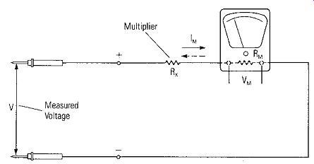
Figure 1-13. The Basic Circuit for a DC Voltmeter
Expanding the equation gives V = IMRx + IMRM
Rearranging, V - l~1RM = IMRx
Solving for Rx gives R
- V - IMRM X - IM
Which may be arranged as R = __'j_ - RM X IM
Example: Let's change the basic meter movement of Figure 1-11 into a dc voltmeter with a 10 volt full-scale range. For this example, V = 10 volts, IM = 1 milliampere
(0.001A), and RM = 105 ohms.
Therefore, R - 10 volts 105 ohms x - 0.001A
Rx = (10,000 - 105) ohms
Rx= 9,895 ohms
... when 10 volts is applied to the circuit of Figure 1-13, with Rx = 9,895 ohms and RM = 105 ohms for the basic meter movement, one milliampere of current will deflect the meter to full scale.
Multirange Voltmeters
The selection of one of a number of multiplier resistors by means of a RANGE switch provides a voltmeter with a number of voltage ranges.
Figure 1-14 shows a multirange voltmeter using a four-position switch and hence four multiplier resistors. The multiplier in each range was calculated using the simple equation for Rx given previously.
A variation of the circuit of Figure 1-14 is shown in Figure 1-15. In this circuit, V4 is a higher voltage range than V,, V, is higher than V,, and V, is higher than V,. As a result, the multiplier resistors of the lower ranges can be included as the multiplier 'or the higher range. An advantage to this circuit is that all multipliers except the first have standard resistance values which are less expensive and can be obtained commercially in precision tolerances. The first multiplier resistor R, is the only special resistor that must be manufactured to meet the particular requirements of the meter movement.
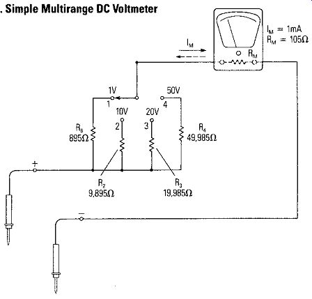
Figure 1-14. Simple Multirange DC Voltmeter
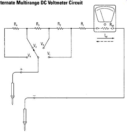
Figure 1-15. Alternate Multirange DC Voltmeter Circuit
Voltmeter Sensitivity
Figure 1-16 shows the typical way a voltmeter is used to make a voltage measurement - in this case, the voltage across resistor R<-
The voltmeter is connected across or in parallel with the circuit component (R,) to measure the voltage. The voltmeter must have a current IM through the meter movement to produce the deflection. This current must be supplied by the circuit and reduces the current through R, as shown in Figure 1-16. It is desirable that the resistance of the voltmeter (Rx + RM) be much higher than the resistance of the device to be measured. This reduces the current drawn from the circuit by the voltmeter; and therefore, increases the accuracy of the voltage measurement.
The value of the voltmeter resistance (referred to as input resistance) depends ,n the sensitivity of the basic meter movement. The greater the sensitivity of the meter movement, the smaller the current required for full-scale deflection and the higher the input resistance. When expressing the sensitivity of the voltmeter, the term "ohms per volt" is used exclusively. It is referred to as the voltmeter sensitivity.
The sensitivity of the voltmeter, S, is easily calculated by taking the reciprocal of the full-scale deflection current of the basic meter movement or: 1 s = IM Example: If a meter movement with a sensitivity of 50 microamperes (0. 000050A) ".ill-scale current deflection is used to make a voltmeter, the voltmeter than has a sensitivity of:
1 1 S = 50 X 10' 0.000050A
S = 20,000 ohm per volt Figure 1-16.
Voltage Measurement
If the full-scale voltage range is set on the 1 volt range, the input resistance is 20,000 ohms; if set on the 20 volt range, the input resistance is 400,000 ohms.
BASIC OHMMETERS
Since electrical resistance is measured in ohms, a common instrument used to measure resistance is called an ohmmeter. Recall, according to Ohm's law, that the resistance, R, in a de circuit can be determined by measuring the current, I, in a circuit as a result of applying a voltage, V. The voltage divided by the current is the resistance value, or V R=y The resistance will be one ohm if there is one ampere of current in a circuit when one volt is applied. By applying a known voltage, V, to a circuit and measuring the current, I, the meter scale can be calibrated to read in ohms of resistance. This is the basic principle of an ohmmeter.
Basic Ohmmeter Circuit
The basic ohmmeter circuit is shown in Figure 1-17. The ohmmeter circuit applies voltage from a self-contained battery to a series connection consisting of a known resistance (RK) to the unknown resistance (Ru)- The meter movement determines the value of the unknown resistance by measuring the current in the circuit.
Ohmmeters are very useful in servicing electronic equipment by making quick measurements of resistance values. The resistance values that can be measured with the ohmmeter vary from a fraction of an ohm to 100 megohms or more. The accuracy is seldom better than 3%; therefore, they generally are not suitable for measurements that require high accuracy.
Since ohmmeters contain their own power source, and depend on their internal calibrated circuits for accuracy, they should be used only on passive circuits; that is, circuits that are not connected to power sources. Connecting them into circuits with other power sources destroys the calibration and can very easily destroy the ohmmeter.
Series Ohmmeter
Let's look again at the basic series-type ohmmeter circuit shown in Figure 1-17.
Notice that when the test leads are open (Ru equals infinity), there is no current through the meter. The meter needle at rest indicates an infinite resistance.
When the test leads are shorted (Ru = 0), there is a full-scale deflection of the needle indicating a zero resistance measurement. The typical meter scale is shown in Figure 1-17. The purpose of Re is to allow adjustment to zero on the scale to compensate for a changing battery potential due to aging, and for lead and fuse resistance. The purpose of RK is to limit the current through the meter circuit to full scale when the test leads are shorted.
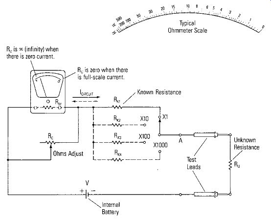
Figure 1-17. A Simple Series Ohmmeter
It is convenient to use a value for RK in the design of the series ohmmeter such that when an unknown resistance equal to RK is measured, the meter will deflect to half scale. Therefore, when the leads are shorted together, the meter deflection will be full scale. Using this criteria, multiple ranges for the ohmmeter can be provided by switching to different values of RK as shown in Figure 1-17. Each RK would set the half-scale value for the respective resistance range, and provides the scale multiplier.
Shunt Ohmmeter
The shunt-type ohmmeter is often found in laboratories because it is particularly suited to the measurement of very low value resistors. The circuit for a shunt-type ohmmeter is shown in Figure 1-18. In this circuit, current has two paths, one through the meter and one through Rx, if there is one. If the leads are open from A to B (Rx ~ x ), then the meter movement reads full scale (adjusted by R,). This is marked as infinity. If the leads are shorted, the meter current drops to zero and the resistance is marked as 0 ohms. When a value of unknown resistance Rx is placed across the terminals A and B, it causes the meter to deflect to some point below full scale. For example, if Rx equals RM, then the meter movement would read half scale.
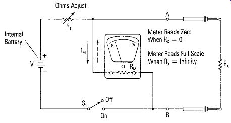
Figure 1-18. A Simple Shunt Ohmmeter
The scales for the two types of ohmmeters are exactly opposite. The series ohmmeter scale has O ohms on the right while the shunt-type has the 0 ohms position on its left. This becomes a good way to identify the type of ohmmeter you might be using.
AC METERS
The most practical means for measuring commonly used ac voltages is by combining a highly sensitive D'Arsonval meter movement and a rectifier.
The Purpose of the Rectifier
The purpose of the rectifier is to change the alternating current to direct current.
The D'Arsonval meter movement is a de movement because of the permanent magnet which sets up the field for the moving coil. The method of using a rectifier to convert the de movement to measuring ac is very attractive because the D' Arsonval meter movement has a much higher sensitivity than other types of meters that may be used to measure ac, such as an electro-dynamometer or the moving iron-vane type meters.
• Bridge-Type Rectifier
The circuit of Figure 1-19 makes use of a bridge-type rectifier which provides full wave rectification. The bridge is generally made of germanium or silicon diodes.
Since a D'Arsonval meter movement provides a deflection that is proportional to the "average" value of the de current. In practice, most alternating currents and voltages are expressed in effective values. As a result, the meter scale is calibrated in terms of the effective value of a sine wave even though the meter is responding to the average value. Effective value is also referred to as RMS (Root-Mean-Squares) value.
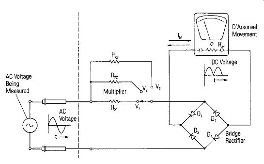
Figure 1-19. AC Voltmeter Using a Bridge Rectifier
A conversion factor which will relate the average and the RMS values of a sine wave may be found by dividing the RMS value by the average value: Erms ~ 1,11 Eavg
This conversion factor is valid only for sinusoidal ac measurements.
Multirange AC Voltmeters
As shown in Figure 1-19, just as for de voltmeters, multiplier resistors can be added to provide multirange ac voltmeters. A more common circuit used for commercial ac voltmeters is shown in Figure 1-20. This circuit uses rectifiers to convert the ac voltages to de in just a little different way. There is current through the meter movement as D, conducts on the positive half-cycle, while D2 conducts on the negative cycle to bypass the meter. Rs is connected across the meter movement in order to desensitize the meter causing it to draw more current through the diode D,. This moves the operating point on the diode curve up into a more linear portion of the characteristic curve. Multiple ranges can be provided by having various multiplier resistors for the required ranges. AC meters normally have lower internal resistance than de meters with the same meter movement.
CALIBRATION, PARALLAX, ETC.
Having covered some of the types of analog meters, let's discuss several items that apply generally. Calibration is one of these.
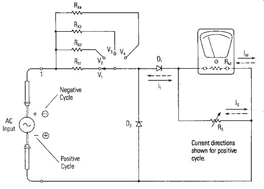
Figure 1-20. A Practical AC Voltmeter Circuit ---- Current directions shown
for positive cycle.
The sensitivity of the meter movement may be determined and the meter calibrated as shown in Figure 1-8. Calibration requires a standard. In this case, it is the current meter used to indicate the current. It is advisable to calibrate the lowest de current range first since all ranges of the instrument will be seriously in error if the basic current range is not accurate. Errors on the various scale may be noted so that readings may be adjusted accordingly. If errors are great, shunts and multipliers would have to be modified inside the meter.
Parallax Error
Parallax error in reading the position of a meter's needle on the scale is due to the position of the head and eyes over the needle. The most accurate reading is obtained when the head is positioned perpendicular to the scales and directly over the needle.
To assure this, many meters have mirrors imbedded in the scales so the needle can be aligned with its image in the mirror. The head is positioned correctly when this alignment is accomplished.
Weak Batteries
Internal batteries will need to be replaced if the "Ohms Adjust" no longer adjusts the needle to R = 0 or R = x. This becomes a good indicator of battery condition.
SUMMARY
Now that we know the characteristics of analog meters that measure current, voltage and resistance, let's look at digital meters.