AMAZON multi-meters discounts AMAZON oscilloscope discounts
There are many types of transistor tests. Transistor testing actually begins with stage isolation and voltage checks, because a high percentage of defective transistors will cause one or more faulty voltages in the stage.
By defective transistor we mean one far enough from its normal ratings to cause the customer to complain. Since this is a practical manual we are not concerned with borderline cases--where a transistor has lost a db or two of its gain, but the effect in the receiver cannot be heard. To find such defects requires laboratory-type equipment, and they are not of interest to the average service technician anyway. Thus, the use of a common ohmmeter for transistor testing will be stressed in this section.
Transistor tests can be either dynamic or static--that is, made under actual operating conditions, where AC signals are fed in and the results measured; or strictly DC tests, which measure the ability of the transistor to respond to a simple battery current.
One form of AC signal test is substitution, where the suspected transistor is replaced in an effort to determine if the new transistor does a better job. In this test the station signal is the test signal: if it shows an improvement in the speaker, the original transistor is assumed to be defective. There are several disadvantages to the substitution test, especially if the transistor is soldered into the circuit and hard to reach. There is also the increasingly difficult problem of having each type of transistor available in the shop, plus the "detuning" action that a new transistor might have on a tuned circuit because of the difference in internal impedance. This detuning action on an IF transformer is not usually too serious if, for example, only one transistor is changed. But when substitution is being tried in several stages in the receiver, the tendency is to leave the new transistor in the radio and put the old one back in stock. If this is done in two or three stages before the defect is found, several circuits may be detuned, resulting in sub standard sensitivity and performance.
So, if the substitution method is to be used, there is a great advantage in isolating the trouble to the proper stage first.
Voltages should also be measured in the suspected stage or stages to make certain the trouble is not due to another defective component or to a poor connection.
Another form of dynamic, or AC, test is to remove the transistor from the receiver and place it in a dynamic tester.
This type of tester usually contains a transistor amplifier or oscillator circuit into which a prescribed amount of signal in put is fed. The transistor is then plugged into the tester and its characteristics noted by the output produced. This type of test, of course, is most accurate if the circuit in the tester is the same as the one in the receiver. Also, for a more accurate test the input signal used with the tester should be nearly the same as the signal fed to the transistor in the radio.
Because this tester is usually quite expensive, it is generally used only with design work in the laboratory.
DC TESTS
Testing transistors by simple DC tests is the more popular method. Although not always perfect, the DC test does catch a high percentage of the defects occurring in transistors after they reach the field.
DC testing can be done in several ways. There are fairly inexpensive testers on the market. One of the first ones, introduced several years ago, tested only small, low-power transistors, principally the RF and IF types. Later, provisions were added for testing power transistors. Most DC testers read leak age and DC gain. They consist of a current meter, plus some resistors and self-contained batteries. The transistor usually must be removed from the circuit before it can be tested.
Almost every electronics technician owns one piece of equipment which contains a current meter and some resistors and self-contained batteries. In fact, it is usually the first piece of test equipment purchased for all-around shop use. We are referring, of course, to the popular VOM (volt-ohm-milliammeter) which has several voltage, current, and resistance ranges. The ohmmeter is actually a battery and ammeter in series, with several values of resistors for selecting the various multiplier ranges. Here, then, is an excellent DC transistor tester, provided it is used properly and its limitations are understood.
So those who have said to themselves, "I can't test transistors because I don't have a tester," may have had one staring them in the face and didn't know it. Most modem VOM's or VTVM's (vacuum-tube voltmeters) can be used for making several DC checks of the transistor.
This does not mean regular transistor testers are not recommended; on the contrary, they are usually quite convenient.
But since instructions are furnished with these instruments, it would serve little purpose to cover their operation in detail here. On the other hand, little has been written about transistor testing by ohmmeter. Moreover, existing shop equipment should be employed whenever possible.
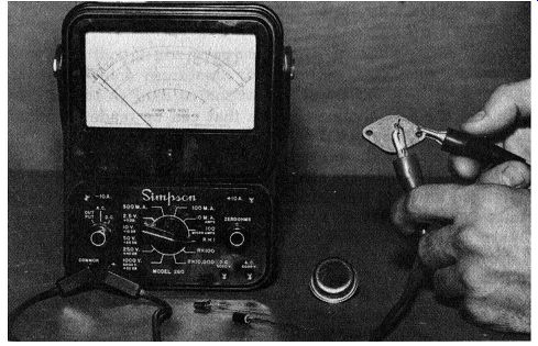
Fig. 7-1. Checking a transistor with an ohmmeter.
TESTING TRANSISTORS WITH AN OHMMETER
Several tests can be made with an ohmmeter. The one used in our tests had 1.5 volts at the ohmmeter leads (measured with a separate voltmeter). Possible tests include one for open leads, a check of both diodes, and a leakage, gain, and transistor identification test.
The last test simply tells whether the transistor is a PNP or an NPN unit.
Since they are all DC tests, the gain checks will have very little meaning for RF and IF transistors, which operate at the higher frequencies. The audio gain test, however, will give an indication of the amplifying ability of audio transistors, because these operate at lower frequencies, which are closer to the DC end of the spectrum.
Most tests must be performed with the transistor removed from the circuit, as shown in Fig. 7-1, except when checking for open internal leads.
Ohmmeters used to gather data for this guide were VTVM's containing a 1.5-volt battery, or VOM's in the 20,000-ohms-per volt class. Older VOM's rated at less than 20,000-ohms-per-volt may not be satisfactory.
Most VOM's have an R X 10,000 range, usually their highest ohms range. Depending on the make of the meter, from 7.5 to 30 volts can be switched into the circuit on the R X 10,000 range. Needless to say, voltages above its maximum voltage rating could immediately damage the transistor. Therefore, this range should not be used.
On the lowest ohms range, such as the R X 1, it is current, not voltage, that must be considered. Most ohmmeters are capable of sending out 100 milliamperes of current on that range. To check, simply turn the ohmmeter to the R X 1 range and connect a separate milliammeter across the ohmmeter leads. The current will probably read 100 mils. This means a transistor with a very low diode resistance might draw close to 100 mils when being checked on the ohmmeter. Therefore, the R X 1 scale should not be used for checking RF and IF transistors. This scale is reserved for audio power and some times for audio driver transistors, as will be discussed later.
Except for these precautions, the ohmmeter is a very safe instrument for most transistor devices.
IN-CIRCUIT TESTS
Checking for Open Leads
One of the few ohmmeter tests that can be made with the transistor still mounted in the circuit is for an open lead in the transistor.
If the voltages at its elements indicate that the transistor may have an open lead, the radio is turned off and the ohm meter is used. We know that NPN and PNP junction transistors contain two diodes, as shown in Fig. 7-2A. The base element in the center is common to both the emitter and the collector diodes.
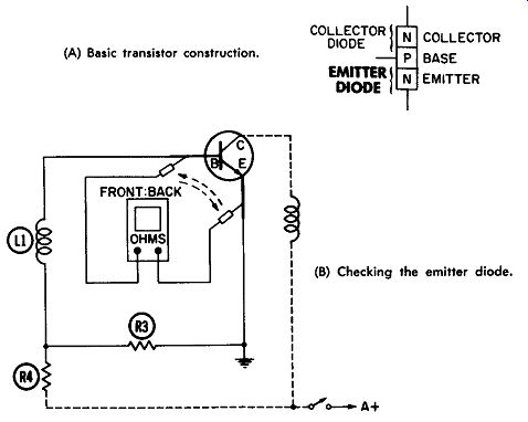
(A) Basic transistor construction. (B) Checking the emitter diode.
Fig. 7-2. An in-circuit test for an open emitter.
We also know that if the ohmmeter leads are placed across a diode in one direction, a relatively low resistance will be read, whereas in the other direction the resistance will be higher. This is true if the diode is functioning properly and one of the leads is not open internally. However, will this check still work with the transistor mounted in the circuit? The answer is yes, it will still work in most circuits, although the front-to-back ratio (the difference between the low and the high reading) will not be as great. The low reading, obtained when the ohmmeter biases the diode forward, should still be low even though the transistor is in the circuit. But the high reading, which represents the reverse (back) bias, probably will not be as high as normal because of the resistors in the circuit.
This can be clearly seen from Fig. 7-2B. The ohmmeter is measuring the resistance of the emitter diode, but note that L1 and R3 are also connected across the ohmmeter. Depending on their values, the high reading will be reduced from what it would be if the transistor had been removed. However, if the proper scale is used, the resistance should change somewhat when the ohmmeter leads are reversed. The R X 100 scale is suitable for most small transistors, and the R X 1 scale, for large power transistors.
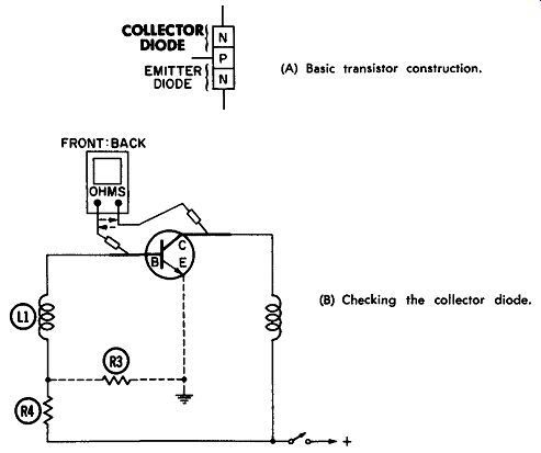
(A) Basic transistor construction. (B) Checking the collector diode.
Fig. 7-3. An in-circuit test for an open collector.
Let's assume the transistor in Fig. 7-2B is good and is mounted in an IF stage. On the R X 100 range, the ohmmeter probably will read 300 to 500 ohms in one direction and over 2,000 ohms in the reverse direction, depending on the value of R3. The exact readings are not important, as long as they are fairly low in one direction, and are higher when the ohmmeter is reversed. For a germanium transistor the low reading should be under 500 ohms; for a silicon transistor, it should be under 1,000 ohms. The high reading in most circuits should be at least twice the low reading. Had the base or emitter lead in Fig. 7-2 been open in the transistor, the reading would probably be above 2,000 ohms in both directions (assuming R3 is at least 2,000 ohms). Failure to get a fairly low reading (less than 1,000 ohms) in one direction would lead us to suspect an open lead.
In Fig. 7-3 the same check is being made on the collector diode. The meter is placed between base and collector, and the reading is noted. Then the meter leads are reversed and again connected between the base and collector. There will be a noticeable change in resistance if the transistor leads are not open and the proper ohmmeter range is used. All but high power transistors are generally checked on the R X 100 scale, as before. As in checking for an open emitter, the low reading for a germanium transistor will be under 500 ohms and the high reading at least twice the low reading. For a silicon transistor, the low reading should be under 1,000 ohms.
There are exceptions when this test will not work with the transistor mounted in the circuit. In some portable-radio output stages, for example, the emitter diode may show a low reading in both directions of the ohmmeter leads. Also, power transistors in audio-radio output stages will show very low resistances because of the shunting effect of circuit resistors, even on the R x 1 scale. However, as long as these exceptions are kept in mind, there should be no confusion. The fact that both readings are not high usually indicates the transistor leads are not open.
Checking for Leakage and Shorts
Ohmmeter tests for emitter-to-collector leakage cannot be made with the transistor mounted in the circuit because all transistors will appear leaky or partially shorted. They can be checked for complete shorts; however, there are very few "zero ohm" shorts except when a power transistor fails. In checking for a complete short, the same scales are used-R X 100 on small transistors and R X 1 on power transistors.
When connected into an output stage, power transistors will normally read very low in resistance. Even on the R X 1 scale, it will be as low as 2 to 5 ohms in some circuits. A complete short, of course, will produce zero ohms in both directions of the ohmmeter leads.
One might ask, "How can I check for partial shorts between the emitter and collector without removing the transistor from the circuit?" The best method is to read the voltages and to thoroughly understand what produces them. (See Sections 5 and 6.) Leaky transistors will probably draw excessive collector current, and this will affect the emitter and collector voltages. If the voltage readings are taken before the transistors are removed, much time can be saved.
OUT-OF-CIRCUIT TESTS
Checking a Transistor Diode
Checking for diode action with the transistor removed from the circuit is quite simple. It is performed in the same manner as before, except that no circuit resistances are involved.
Therefore, a much higher front-to-back ratio is obtained.
The back, or reverse, reading is generally very high when read on the recommended range of the ohmmeter. The front, or forward, resistance reading is generally about the same as when the reading was taken in the circuit.
Selecting the Proper Range
To perform this test, first set the ohmmeter on the proper range. For small, low-power transistors like those in RF, IF, or converter stages, the R X 100 range is recommended. (If the ohmmeter does not have an R X 100 scale, R X 1,000 can be used for out-of-circuit checks. On in-circuit tests, the R X 1,000 range makes the resistance read too low.) For small audio transistors, such as the driver or output transistors in portable radios and the driver transistor in automobile radios, the R X 100 scale is also recommended for the diode check.
Large power transistors like those in the output stage of automobile radios or hi-fi amplifiers can be checked on the R X 10 or R X 100 scale, but never on a higher one. Higher scales make the diode appear shorted. Remember that we are now assuming the transistor being checked has been removed from the circuit. Power transistors must also be allowed to cool to room temperature before being checked.
Here is a summary of the recommended ohmmeter ranges for checking transistor diodes which have been removed from the circuit:
Low-power RF and IF types-R X 100
(or R X 1,000 if R X 100 is not available.)
Small audio driver types-Same as above
Large power transistors-R X 10 or R X 100.
(B) Between the base and collector.
(A) Between the base and emitter.
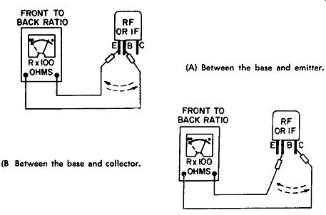
Fig. 7-4. Checking the front-to-back resistance ratio of a transistor.
Performing the Diode Test
After removing the transistor from the circuit and selecting the proper scale, connect the ohmmeter leads between the base and emitter, as shown in Fig. 7-4A. Observe the reading, and then reverse the meter leads, placing them across the same two transistor leads. Again observe the reading. One reading should be rather high and the other fairly low, indicating a good front to-back ratio.
The same test is then performed on the other diode section by placing the leads between the base and collector, as shown in Fig. 7-4B. The base lead, of course, is common to both diodes, so it is used during both tests. In Fig. 7-4A the emitter diode of a small RF or IF transistor is being checked, and in Fig. 7-4B the collector. Note that the R X 100 scale is used.
Note also that the highest reading on both diodes is completely at the high-resistance end of the scale. This is quite typical for small transistors, which should have a very high reading on each diode in the reverse direction. In fact, don't be surprised if the meter needle doesn't budge from the high resistance end of the scale-it does not mean the diode is open.
However, when the ohmmeter polarity is again reversed, the resistance should be much lower. If a low reading cannot be obtained in one direction of the ohmmeter leads, then it is safe to assume one of the transistor leads is open.
Small transistors, including RF, IF, and audio driver types, usually show a very high reverse diode reading and a forward reading of less than 1,000 ohms (less than 500 ohms for germanium). Large power transistors usually have a reverse reading of 5,000 ohms or higher and a forward reading of less than 100 ohms for each diode.
A summary of these normal transistor diode readings is shown in Table 7-1.
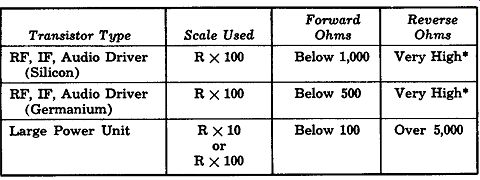
TABLE 7-1.
Normal Transistor Diode Readings
It is not necessary to read the actual value of ohms. The highest range of VOM's is not used because from 7.5 to 30 volts may appear across the leads on that range.
Ohmmeter Battery Polarity and Voltage
The common, or ground, lead of some ohmmeters does not always have negative voltage on it. The ground may actually be positive and the probe lead negative because of the way the internal battery is connected when the meter is switched to read ohms. However, this makes no difference in our tests because we are simply checking for a resistance change when the lead polarity is reversed. This is mentioned at this point merely because some technicians may purposely connect their meter in the forward direction across a diode-plus lead to P-type and ground lead to N-type material-and expect to get a low reading. The reading will depend on the meter design and whether the plus lead actually is positive.
TABLE 7-1.
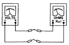
Fig. 7-5. Checking the ohmmeter lead polarity.
Those interested in finding out which way their ohmmeter is designed can simply connect it to a separate voltmeter, the two common and two probe leads being connected together as shown in Fig. 7-5. If the voltmeter reads upscale, the positive lead is actually positive and the common lead is negative. If the voltmeter reads below zero, however, the ohmmeter is of the opposite polarity. (This would be a good time to find out if your ohmmeter has the conventional 1.5 volts when switched to the R X 1 range.)
Checking the Emitter-to-Collector Leakage
The resistance between emitter and collector is often referred to as the leakage resistance.
The leakage test is made with the transistor disconnected from the circuit and the ohmmeter connected between emitter and collector; the base lead is not used and is therefore left open. Because the base lead isn't connected to anything, this is sometimes called an open-base test-a confusing term because it sounds as if the transistor is being checked for an open lead, which isn't true. Open leads are found by checking the transistor diodes, as discussed previously.
The amount of resistance between emitter and collector depends on the following:
(1) Transistor Type-In this guide we are concerned only with junction transistors. However, there are many different processes used to build junction transistors, making the leakage resistances vary tremendously.
(2) Gain-Has less effect on the leakage reading than the transistor type. However, it does have some effect, which is one reason a definite leakage value cannot be assigned to each transistor.
(3) Amount of Contamination-The more a transistor is contaminated by moisture or other unwanted impurities, the poorer the showing on the leakage test, compared to other transistors of the same type and gain.
(4) Condition of Base Area Between Emitter and Collector
If subjected to too much current, the transistor may have a broken-down area between the emitter and collector. The leakage test will therefore be very poor because the transistor will appear totally or partially shorted.
(5) Transistor Temperature-The hotter the transistor, the lower its resistance between emitter and collector. There fore, the leakage test should be performed only at room temperature, when the transistor is cool to the touch.
(6) Type of Ohmmeter-Our checks were taken with ohm meters employing a 1.5-volt battery.
Selecting the Ohmmeter Range
When checking the transistor for leakage, be sure to use the proper range.
Since power transistors normally have the lowest resistance, the R X 1 scale must be used with them. Even then, the transistor may appear to be almost shorted unless it is disconnected from the circuit and cooled to room temperature.
With RF and IF types, the R x 100 or R x 1,000 scale can be used. Audio driver and other small transistors are checked on the R X 10 or R X 100 range.
In summary:
Low-power RF-IF types-R x 100 or R X 1,000
Audio driver types-R X 10 or R X 100
Large power transistors-R X 1
Performing the Leakage Test
The leakage test is a very simple one. After removing the transistor from the circuit and letting it cool, place the ohm meter between the emitter and collector, as shown in Fig. 7-6.
(The base lead is left open and is not used during the test.) Note the reading; then reverse the ohmmeter leads and read the leakage resistance again. We are not interested in finding the front-to-back ratio. In fact, the resistance does not have to change at all. The important thing is that the resistance must not be "0," because that would indicate a shorted transistor provided the proper ohmmeter range was used. The mistake most often made is to measure a power transistor on some range other than R X 1. This will make a good unit appear to be shorted.
If the transistor is not shorted, the next most important consideration is whether the reading is fairly steady or not.
This is more important than the actual value of resistance.
For normal units, the leakage resistance will hold fairly steady and will not "drift" quickly after the meter is connected. A very slow, steady drift which covers a period of several minutes is not to be concerned about, since it is probably due to tempera ture changes within the transistor.
Typical Leakage Readings
In the foregoing tests it is assumed that the transistor is removed from the circuit. In the circuit, you can check for a dead short between emitter and collector, but that is all. Out of the circuit, small transistors measure anywhere from 100 ohms to almost infinity, depending on the particular transistor. Some of them measure so high on the R X 100 range that they appear to be "open," but don't worry about this. Assuming that the transistor has passed the "diode" checks, it cannot be open.
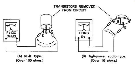
(A) RF-IF type. (Over 100 ohms.) (B) High-power audio type. (Over 10 ohms.)
Fig. 7-6. Testing transistor for leakage.
Typical power transistors will measure anywhere from 10 ohms to 500 ohms between emitter and collector, on the R X 1 range.
Summary of Leakage Tests
When the resistance between emitter and collector is "0," or when it changes or "drifts" quickly after the ohmmeter is applied, the transistor is considered to be defective.
The limits are difficult to set because so many things influence the readings. But by using the "guide-lines" given here, the troubleshooter can quickly confirm what he already suspects from the conduction, bias, and other voltage readings.
Power transistors generally measure lower leakage resistances than small transistors and must be measured on the R X 1 range.
CHECKING TRANSISTOR GAIN
DC gain tests, such as with an ohmmeter, mean very little for RF and IF transistors. For audio units, however, a fairly good estimate of their amplifying ability can easily be made.
We will begin, therefore, with the audio gain test.
Even this test is not used too often. Experience has shown that transistors which suffer gain breakdowns will almost always have a bad diode or suffer from a leakage defect; so they will be caught during previous tests. Very seldom does a transistor have a noticeable gain problem without one of the other defects, assuming it at one time worked normally.
Our simple gain test will mean little if the transistor is leaky or has bad diodes. Hence, these tests should always be made first.
For gain checks, it is important to know the voltage and polarity on the ohmmeter leads. As stated before, the common lead is actually connected to the positive side of the internal battery in some ohmmeters.
Audio Gain Test
To check the gain of a PNP power transistor, set the ohm meter on the R X 1 scale. Connect the lead which has the negative voltage on it to the collector, and the positive lead to the emitter (Fig. 7-7A). (This is the polarity used on a PNP transistor when in the circuit.) The amount of leakage should be well over 10 ohms, as described in the leakage test instructions.
Now connect a 1,000-ohm resistor in series with a switch, between the base lead and the collector or case of the transistor, as shown in Fig. 7-7B.
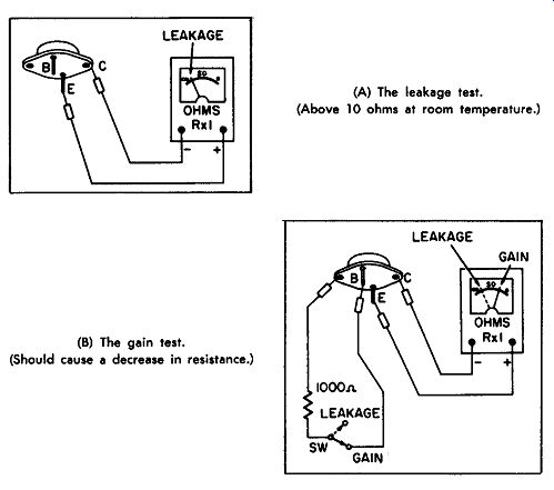
(A) The leakage test. (Above 10 ohms at room temperature.) (B) The gain test. (Should cause a decrease in resistance.)
Fig. 7-7. Testing the gain of an audio transistor.
When the switch is closed, the resistor brings a small negative bias to the base lead from the ohmmeter battery, causing the transistor to conduct more heavily. As a result, the resistance decreases between the emitter and collector. This decrease, which is read on the ohmmeter, means more current is being conducted. In general, the lower the resistance reading after the 1,000-ohm resistor is switched into the circuit, the higher the transistor gain. Typical resistance readings for power transistors are from 5 to 40 ohms.
One major precaution when performing the test in Fig. 7-7B--if the ohmmeter does not show a lower resistance after the 1,000-ohm resistor has been connected, reverse the ohmmeter leads and try again. Reversing the leads will prevent any con fusion due to the wrong ohmmeter lead polarity. (The wrong polarity will not put the proper bias on the transistor base.) Although, a transistor which measures 7 to 15 ohms probably has a higher gain than one which reads 30 ohms, it will not necessarily work any better in the circuit. A circuit de signed for a lower-gain transistor may be unstable, and may even oscillate or motorboat if an extremely high-gain unit is substituted.
Small audio driver transistors may be checked for DC gain in a similar manner. However, they should have a maximum power rating of at least 75 milliwatts; otherwise, the transistor may be damaged. Also, the ohmmeter being used should not have more than 1.5 volts at the leads.
Audio transistors which read over 50 ohms on the gain test are usually very low-gain units, but this does not mean they will not work in certain circuits. Transistors in power supplies or switching circuits, for example, are often purposely produced with very low gain.
Two different audio transistors which measure very close to the same resistance during the leakage test (and also during the gain test) are usually pretty well matched. If both transistors measure within 20% of each other, the match is very good, and 30% is usually passable.
RF-IF Gain Test
As stated previously, the RF-IF gain test means very little and therefore is seldom used. RF and IF transistors often perform in a completely different manner in the circuit than they did during the DC gain test.
The R X 100 scale is used, and the transistor is first checked for leakage and a good diode ratio. Then the same procedure described for the audio gain test is used, except the meter is left on the R X 100 range, and the 1,000-ohm resistor is re placed with a 10,000-ohm resistor.
If the transistor is a PNP type, connect the negative lead to the collector and the positive lead to the emitter. Then connect the 10,000-ohm resistor between the base and collector. The resistance on the ohmmeter should immediately decrease. If it doesn't, reverse the ohmmeter leads, which may have been of the wrong polarity. NPN units require a positive voltage on the collector and a negative one on the emitter.
The resistance read on the ohmmeter will almost always be less than 5,000 ohms-typical values being from 500 to 4,000 ohms. Although the low values mean a high DC gain, the signal-amplifying ability will not necessarily be high.
IDENTIFYING TRANSISTOR TYPES
If the polarity of the ohmmeter battery is known, the transistor can be identified as an NPN or PNP unit. Place one lead of the meter on the collector and the other on the base (Fig. 7-BA), using the same range as for checking the front-to-back ration of a diode. Then reverse the ohmmeter leads and check the collector diode again, noting which lead polarity gave the lower reading.
The lowest resistance will be obtained when the ohmmeter lead polarity matches the internal polarity of the transistor.
In other words, when the Negative voltage is placed on the N material and the Positive voltage on the P material, a low
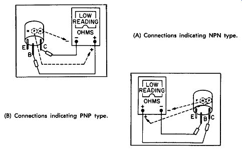
(B) Connections indicating PNP type. (A) Connections indicating NPN type.
Fig. 7-8. Method of determining the transistor type.
reading will be obtained. So, for an NPN transistor (Fig. 7-8A), the low reading will be obtained when the negative lead is on the collector and the positive lead is on the base. For a PNP transistor (Fig. 7-8B), just the opposite is true.
The same check could be made on the emitter diode, between the base and emitter.
Another way of stating this makes it easy to remember: When either diode is biased forward, the polarity connected to the base lead is the middle letter in the transistor type, such as NPN or PNP. So, a glance at the meter leads will tell which type the transistor is.
But remember that some meters are actually plus on the common lead and minus on the positive lead because of the internal battery connections. One example of this "reversed" polarity is the Triplett Model 630.
SUMMARY OF OHMMETER TESTS
Several transistor tests can be made with an ohmmeter.
These are not foolproof tests, but they will help to confirm what is already suspected by the conduction and bias voltage checks.
Transistors can be checked for:
1. Open leads
2. Shorts
3. Low-frequency gain
4. Polarity type (NPN or PNP)
5. Construction type (germanium or silicon)
Important points to remember when using the ohmmeter to check transistors are:
1. Ohmmeter Range (small units)--Use the RX 100 range for most tests on small transistors.
2. Ohmmeter Range (large units)--Use the RX 1 range for most tests on power transistors.
3. Temperature--Power transistors will appear shorted if checked when hot. Allow to cool to room temperature.
4. Transistor Diodes--When checking between the base and one of the other elements, a low reading should be obtained with one direction of the meter leads (below 500 ohms for germanium units; below 1000 ohms for silicon units). Also, the ratio between the low reading and the high reading should be at least 2:1.
5. Transistor Leakage--The resistance between the emitter and collector is called the "leakage" resistance. This resistance varies considerably because of the different manufacturing processes; no definite limits can be given. Watch for complete shorts and a quick drift toward a short as the meter is applied.