AMAZON multi-meters discounts AMAZON oscilloscope discounts
If we wish to measure or observe a signal, we must be concerned with not only the frequency of the signal , but also its voltage and impedance levels. The voltages encountered may vary considerably. For example, in television receivers, only a few microvolts may appear at the input of the tuner, but up to 20,000 volts may be applied to the picture tube.
Voltages can be AC, DC, or a combination of both. Alternating voltages may consist of simple sine waves of various frequencies, or a complex wave combining harmonically related sine waves. Alternating current signals may also have a DC potential . This DC may be essentially "clean," or it may have a certain amount of ripple. There are also pulsating DC voltages, like the ones which are found at the output of a rectifier.
When the voltage is measured or observed at some point in a circuit--whether with a meter, an oscilloscope, or a tracer-the impedance at that point is important. This fact is often overlooked by even the more experienced technicians.
Resistive circuit loading becomes a problem when the test equipment has a low input impedance. However, such loading can be minimized by the use of high-impedance measuring instruments. Another point that should be considered is the effect of stray fields on scope and meter indications. The instruments themselves cannot differentiate between desired and undesired signals. They must therefore be shielded from extraneous electromagnetic and electrostatic fields which could introduce noise, hum, or other interference. Enclosing test equipment in a metal case helps shield against such stray fields. For maximum shielding, however, the leads from the test equipment must also be shielded.
In sensitive circuits, unshielded test leads sometimes produce rather puzzling effects. They may also act as antennas and radiate signals from one part of the circuit to the other. In this way, cross coupling or feedback occurs between sections normally isolated from each other.
Oscillations may then occur, which may result in giving erroneous readings.
Shielding the test leads does indeed exclude interference. Unfortunately, it adds something else-shunt capacitance. At the higher frequencies, shunt capacitance lowers the input impedance of the instrument, thereby adding to the loading of the circuit under test.
Thus, although gaining the desired shielding, we do so at the expense of undesirable shunt capacitance.
TEST LEADS
The simplest probe (if it can be called a probe) is the test leads in Fig. 1-1. Essentially, such lead? are an extension of the input circuits in the test instrument. Rarely are test leads alone fully satisfactory, except for low-impedance, high-level measurements in relatively low frequency circuits. They are quite good for such simple measurements as DC resistance. In r-f, i-f, video, or high-fidelity audio tests, however, test leads can introduce erroneous indications.
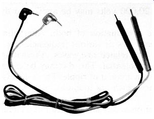
Fig. 1-1. Test leads. Courtesy General Cement Mfg. Co.
DIRECT PROBES
The shielded direct probe (sometimes called a straight-through probe) is simply a shielded cable terminated in a test prod. Fig. 1-2 shows its internal construction . It is generally used with signal tracers, vacuum-tube voltmeters, and oscilloscopes, adding an overall capacitance of approximately 100 pf to their input circuits. The frequency range over which a direct probe can be used depends on (1) the complexity of the signal to be observed and (2) the impedance of the circuit to be measured. Actually, the maximum frequency range of a direct probe depends on the impedance of the circuit being tested. If circuit impedance is low, all low-frequency voltages (even those with complex waveforms) can be measured. However, as circuit impedance increases, the shunting effect of the probe becomes more pronounced.
GROUND CUP, SHIELDED CABLE
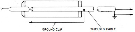
Fig. 1-2. Internal construction of a shielded direct probe.
Hence, the direct probe is not suitable for frequencies above several hundred cycles in some cases; in other cases, it is satisfactory for frequencies of several thousand cycles.
The direct probe is not absolutely accurate for measuring and observing complex waveforms, particularly those containing high-frequency pulses. Loading by the cable capacitance modifies the waveshape too much.
(A) Waveform obtained when unshielded (b) Waveform obtained when shielded test leads are used. direct probe is used. (C) Cannot be used at i-f stage. (d) Can be used at power supply.
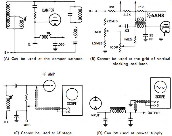
Fig. 1-4. Examples of circuits where direct probe can or cannot be used.
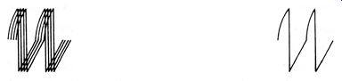
Fig. 1-3. The effect of a shielded direct probe on a waveform.
However, there are places where this probe is most useful-for example, to check ripple in power supplies and plate-supply circuits, and to signal-trace and observe audio, transistor, and other low impedance circuits. The additional shunt capacitance placed across the circuit under test is usually between 50 and 150 pf, depending on the length of the cable and its capacitance per foot.
(A) Can be used at the damper cathode. (b) Cannot be used at the grid of vertical blocking oscillator.
When a direct shielded probe is used, maximum sensitivity from the test instrument can be obtained because the probe contains no attenuating elements. To help prevent pickup of unwanted signals when a direct connection is required, a shielded probe, rather than unshielded test leads, should be used.
The importance of choosing a fully shielded direct probe is illustrated in Fig. 1-3. The waveform in Fig. 1-3A was obtained by using ordinary test leads; in Fig. 1-3B, a shielded direct probe was used.
The signal displayed is the same, except that the waveform in Fig. 1-3A is very jittery because of hum picked up by the open leads.
In order not to excessively load or otherwise disturb the circuit un
der test, the probe should have an input impedance at least ten times higher than the source impedance. Some examples of where and where not to use a direct probe are shown in Fig. 1-4.
The impedance of the circuit under test must not be so sensitive that it would be detuned or otherwise disturbed by a shunt capacitance of 100 pf or so from the probe. Fig. 1-4A shows a horizontal-damper circuit. A direct probe can be readily used at the damper-tube cathode, where the capacitance is at least 0.1 mfd. On the other hand, suppose that we applied a direct probe at, say, the grid of the vertical blocking oscillator in Fig. 1-48. Because of the lower capacitance to ground (only 25 pf), the added 100 pf from the probe would drastically alter the circuit performance, or even disable the circuit. When we are trying to decide whether or not to use a direct probe, it is not so much the operating frequency that is important; rather, it is the capacitance and impedance levels. To further explain this statement, let's use the illustrations just discussed as examples. The frequency of the voltage at the damper cathode in Fig. 1-4A was 15,750 hz, yet it was only 60 hz at the grid of the vertical blocking oscillator in Fig. 1-4B. The direct probe could not be used at the blocking oscillator grid, simply because of the high circuit impedance. The mere fact that a direct probe could measure a signal with a frequency of 15,750 hz at the damper cathode would indicate that impedance--not frequency--was the determining factor here.
Aside from its loading effect, a direct probe alone does not attenuate the voltages applied to it. In other words, the same amount of voltage applied at the tip of the probe will be applied to the input terminal of the test instrument. For this reason, a direct probe used with an oscilloscope must never contact any points exceeding the maximum voltage that can be safely applied to the scope input. Therefore, to measure voltages beyond the capability of the measuring instrument, we must use a low-capacitance or high-voltage probe (both types will be discussed later), or a simple divider of two or more resistors.
Because of its severe capacitance shunting effect, a direct probe should not be applied directly to the output circuit of a video detector.
Doing so will not only seriously reduce the apparent bandwidth of the circuit, but may also cause parasitic oscillation. Only a low-capacitance probe is suitable here. Use of an isolation probe or simply an isolation resistor is sometimes suggested at the video-detector output. However, such a resistive-type isolation probe exhibits a low-pass filtering action, which will be discussed later in this section.
A direct probe used with an oscilloscope is not suitable for checking the television i-f amplifier because the frequencies encountered are beyond the capable response of the oscilloscope. A demodulator probe would be required here. However, if you do use a direct probe at the grid of an i-f amplifier (as shown in Fig. 1-4C), you will probably get a weak or greatly disturbed response because of regeneration at some frequency within the receiver i-f band. This regeneration will overload the i-f stage causing the i-f tube to be overdriven. The resulting wave shape will be distorted and not at all indicative of the true circuit performance.
A direct probe is suitable for observing and tracing hum or ripple in a power supply. (See Fig. 1-4D.) The small shunt capacitance of the probe does not affect the extremely high shunt capacitance in the power-supply circuit. The biggest advantage of the direct probe is that it lets us use the full sensitivity of the oscilloscope to measure the rather low ripple voltages in most well-filtered power-supply circuits.
(Remember that 600 volts DC is the maximum that can be applied to the vertical-input terminals of most oscilloscopes. Never exceed this level!) On the other hand, trying to measure ripple voltage of a television high-voltage supply with a direct probe would be disastrous.
(A) The probe. SHIELDED CABLE. (b) Probe circuit. Courtesy Radio Corporation of America
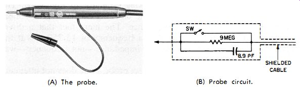
Fig. 1-5. A combination direct-low-capacitance probe.
Even though the ripple may be relatively low, the high DC potential (in the thousands of volts) is far beyond the capabilities of the oscilloscope (unless the proper attenuating probe is used). An interesting combination is the direct-low-capacitance probe, in Fig. 1-5, using a resistor and a capacitor in parallel. This combination, together with the compensating capacitance in the oscilloscope, forms a low-capacitance probe. Also note that the isolation resistor has a value of 9 megohms. This higher-than-usual value gives a 10-to-1 attenuation when the probe is used with any of the oscilloscopes for which it is designed. Consequently, when the combination is used as a low-capacitance probe, the input signal must be sufficient to compensate for this loss. When the switch is closed, this probe becomes simply a direct shielded probe.
It is sometimes desirable to observe current waveforms in deflection circuits. This can be done by connecting a 1-ohm resistor in series with the circuit. When a direct probe is placed across this resistor, the oscilloscope will indicate the exact waveshape of the current. The shunting of the direct probe on this 1-ohm resistor is negligible.
ISOLATION PROBES
There are two types of isolation probes--one for oscilloscopes and another for vacuum-tube voltmeters. Both probes have the same circuit, except that the vtvm probe uses an isolation resistor with a value of 1 megohm or higher, whereas the oscilloscope probe uses one between 10K and 50K ohms. For this reason, the probes are not interchangeable. The time constant of the isolation resistor and distributed capacitance is very important.
Fig. 1-6 shows an isolating probe for a DC vacuum-tube voltmeter.
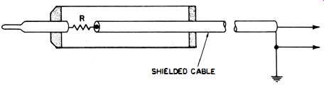
Fig. 1-6. Internal construction of an isolation probe for a doc vtvm.
These probes usually contain a I-megohm resistor near the tip. The term isolation describes the function of the resistor-to isolate the test instrument so it will not interact with the circuit under test. The isolation resistor also reduces the effects of hand capacitance and shielded-lead capacitance. Otherwise, loading due to the shunting capacitance of the shielded lead, plus the input capacitance of the vtvm, would produce erroneous readings in sensitive circuits.
The isolation resistor and the distributed capacitance across it not only isolates the vtvm from the circuit under test, but also keeps out the high-frequency AC component. This resistor is usually part of the voltage-divider network in the vtvm input circuit; as such, its value is extremely important to the accuracy and calibration of the meter.
When a vtvm DC probe contains an isolation resistor, the effective input capacitance of the DC probe is usually reduced to approximately 1 pf. The isolation resistor also prevents the shielded cable from acting as a resonant stub and thus causing erroneous readings at frequencies where the cable length is an integral or fractional part of a wavelength. If there were no isolation resistor, the input capacitance would be around 100 pf. Direct-current voltages in r-f and i-f-amplifier circuits, as well as in local oscillators, would be most difficult, and frequently impossible, to measure.
Sometimes it is desirable to change the resistor in the probe to one of a higher value, or to add an isolation resistor in order to improve the isolation and lower the shunting impedance. We do this by adding another resistor externally. By making this resistor equal to the total input resistance of the vtvm (the resistance of the voltage divider plus the original isolation resistor), we will double the input impedance.
Meanwhile, we will also cut the full-scale sensitivity in half. For example, if the voltage-divider resistance in the vtvm is 10 megohms and the isolation resistor in the probe is 1 megohm, and we add an additional 11-megohm resistor in series, we will now have a 22-megohm input impedance-double that of the original value. However, all readings must now be multiplied by 2. For example, what used to be a 10-volt full-scale reading is now 20 volts. Thus, if we read 8 volts with the range-selector switch at the 10-volt position, we actually have 16 volts at the test point.
We can go one step further; we can triple (or even quadruple) the input impedance of a vtvm if we wish to measure voltages in extremely sensitive circuits (in very low-current, high-impedance, high-voltage circuits, for example). If we quadruple the input impedance, we must multiply by 4 any voltage readings obtained. Thus, in the previous example where the meter had an 11-megohm input impedance, we can put 33 megohms in series with the probe, giving a total input impedance of 44 megohms. However, if we again read 8 volts on the 10-volt scale, we would actually be measuring 32 volts . If the readings are too low, we switch to the next lower voltage range . Vacuum-tube voltmeters have for many years required separate probes for DC and for AC voltage and resistance measurements. This is necessary because of the isolation resistor in a DC probe. Some manufacturers have overcome the disadvantage of separate probes by placing the resistor in a housing which can be attached to the probe tip for DC voltage measurements, or by installing a switch in the probe handle. This switch inserts the isolation resistor in the circuit for DC measurements, but takes it out for other readings . Such a switch should be relatively simple to operate. Yet, it must be compact, so the probe can be handled easily . An isolation resistor used in conjunction with the oscilloscope will help facilitate waveform observance at the video-detector load. In this way the i-f response curve can be seen when a sweep signal is being applied. The isolation resistor serves a dual purpose : (1) As an r-f filter, it prevents any i-f signal which might have passed through the detector circuit from reaching the oscilloscope and being radiated back into the receiver. (2) Together with the capacitance of the cable and oscilloscope input, the isolation resistor forms an integrating network which bypasses and greatly attenuates any signal above several kilocycles. This results in a sharper marker pip on the i-f response curve. Since this curve consists of relatively low-frequency components, its shape will not be altered by the use of this probe. Any 15,750- hz interference will be greatly reduced, or even eliminated, by the filtering action which occurs with the probe above several kilocycles (unless the interfering signal is excessively strong) . Sometimes an unshielded isolation probe is used with an oscilloscope . However, such a probe tends to pick up horizontal sync-pulse radiation and power-supply hum when not connected to the circuit under test. These extraneous signals will disappear, however, when the probe is connected to the circuit. Any undesired signals observed during the test are therefore usually from the circuit itself. Although an unshielded isolation probe can be used with a scope for testing in some circuits, a good, shielded isolation probe is still hard to beat.
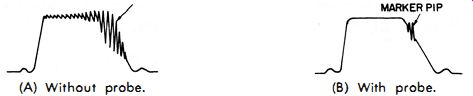
Fig. 1·7. The effect of a resistive isolation probe on the sharpness of the
marker pip. (A) Without probe. (B) With probe.
If direct-connection test leads or probes are used at critical circuit points (at the converter grid of a television front-end, for example), a feed-back loop may tend to be established between the receiver, oscilloscope amplifier, and power line. This loop may produce undesired oscillation. An isolation resistor inserted into the circuit, however, will suppress this tendency by isolating the test circuit from the oscilloscope. Fig. 1-7 shows the effect of such a resistive isolating probe on the marker pip. Fig. 1-7 A shows the marker indication when the probe is not used; Fig. 1-7B, when it is. The time constant (formed by the isolating resistor and the capacitance of the shielded cable and oscilloscope) of this filter must be such that marker displacement is not introduced on even the steepest portion of the response curve. Such displacement could be caused by an excessively large time delay in the filter. Thus, the values of the isolation resistor and filter capacitor (if a separate unit is added) should be chosen to give a relatively short time-constant.
Careful observation of the beat-frequency marker signal on a response curve will show that the high-frequency components are at either end of the marker. At zero beat and nearby, the frequencies are very low. Therefore, a simple RC filter will more or less suppress the higher frequencies (depending on the value of the resistor and capacitor) without affecting the low-frequency component or zero beat.
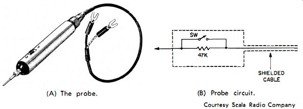
Fig. 1·8. A combination direct isolation probe for use with an oscilloscope.
(A) The probe. (B) Probe circuit.
A combination direct and isolation probe to be used with an oscilloscope is shown in Fig. 1-8. This probe is designed to minimize circuit loading and pickup from stray fields near the chassis. Careful shielding tends to prevent false indications caused by stray voltages.
The input cable is designed to add the least possible capacitance to the oscilloscope input circuit in order to reduce the shunting effect of the probe. When the switch is closed, we have a direct probe; when open, we have an isolation probe with a 47,000-ohm resistor between the oscilloscope input and the circuit under test.
SHIELDED CABLE
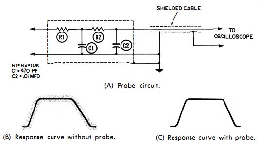
Fig. 1-9. Isolation-filter probe circuit and its effect on response-curve
indications. (A) Probe circuit. (b) Response curve without probe. (C) Response
curve with probe.
If we connect an oscilloscope directly across the load resistor of a video-detector output circuit, the scope may operate as a resonant stub unless resistive isolation is used. Stub action is reflected-via the interelectrode capacitance of the video detector-into the last i-f stage.
Such a disturbance will not only detune the last i-f transformer, but may? result in uncontrollable oscillation of the i-f amplifier.
Besides providing a low-pass filter action, the isolation resistor also raises the input impedance of an oscilloscope. For example, if we have a total capacitance of 150 pf (by total we mean the shunt capacitance of the shielded cable plus the input capacitance of the oscilloscope) the reactance at 500 khz is 2000 ohms. Therefore, if we take a measurement in a 500- khz circuit, we would be shunting it with 2000 ohms. At higher frequencies, this shunting effect would be even more pronounced. Now, if we use an isolation resistor of anywhere between 10K and 50K ohms, we have automatically minimized the shunting effect to at least the value of the isolation resistance. This reduction in the shunting effect is sometimes of the utmost importance--for example, when excessively high-frequency signals are causing a fuzzy alignment curve. If the isolation resistor alone is not a good enough filter, we can build a low-pass filter which acts like the isolation resistor and the distributed cable capacitance, only more so. Sometimes a 0.001-mfd up to a 0.01-mfd capacitor across the vertical-input terminals of the scope will do the job. However, a more elaborate isolation filter like the one in Fig. 1-9 is often preferred. Fig. 1-9 A illustrates its circuit; Fig. 1-9B, the response curve when the filter is not used; and Fig. 1-9C, the response curve when the filter is used. With a sweep frequency of only 60 to 120 cycles, a good scope response up to only 10 khz or so is sufficient for proper response or reproduction of the sweep-generated response curve of a tuned circuit or amplifier.
The complete isolation-filter network in Fig. 1-9A should be made into a probe and connected to the oscilloscope through a shielded cable. Resistor R1 is the isolation resistor; and C1, C2 and R2 form a pi-type, low-pass filter.
For ease in making measurements with a vtvm or vom, a polarity reversing probe is unique. Transistors, for example, usually require a front-to-back resistance ratio check. A polarity-reversing probe used with an ohmmeter will greatly speed up this type of check by eliminating the need to reverse the test leads. Instead, the switch on the probe automatically reverses the polarity of the test leads.