AMAZON multi-meters discounts / AMAZON oscilloscope discounts
In the previous sections, we have discussed practically every component used in electronic equipment and the methods of connecting them. Also, we have shown how some times several components are combined in a single unit. However, before any of these components can serve a useful purpose, they must be connected to form a circuit.
What is a circuit? A circuit is any combination of components connected in such a manner that it will perform its intended function. There are two general types--passive and active.
A passive circuit is one which does not contain a tube or transistor ; that is, it is merely a combination of resistors, capacitors, and coils. In certain applications, such a circuit can perform many useful functions. For example, frequencies below a certain point will pass through the circuit in Fig. 1A and on to the following circuit. Above a certain frequency, the signals are shunted (bypassed) to ground by the capacitors. The opposite is true of the circuit in Fig. 1B. This is a high-pass filter. Below a certain frequency, the signals are shunted to ground through the coils; above this frequency, they are passed on to the next stage.
There are many passive circuits, or configurations as they are sometimes called, like the ones in Fig. 1. Each performs a definite purpose in the over-all operation of the unit.
While power must be supplied to a passive circuit, an active circuit is one which supplies power. It may be composed of batteries, a generator, or an amplifier.
To understand the operation of active circuits, in the remaining pages of this section we will examine some of the basic circuits and see how they operate.
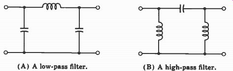
Fig. 1. Two passive circuits. (A) A low-pass filter. (B) A high-pass filter.
RECTIFIER CIRCUITS
Perhaps the simplest circuit is the rectifier shown in Fig. 2. Recall that in order for a diode tube to conduct, the plate must be more positive than the cathode. Then electrons will flow from the cathode to the plate. The plate (pin 5) is connected to an alternating voltage. Hence, during the periods when the plate is positive, electrons will flow from the cathode to the plate. However, these electrons must come from somewhere. They flow from ground, up through R2, then through R1 to the cathode. Since electrons flowing through a resistor produce a voltage drop across it, a voltage (which will be positive at the top) will be produced across R2. This voltage will also be present on capacitors C1 and C2.
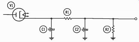
Fig. 2. A typical rectifier circuit.
During the period when the alternating voltage on the plate is negative, the tube will not conduct. But since the primary purpose of a capacitor is to store electrons, it will hold the charge previously placed on it and maintain the voltage relatively constant. Thus, while AC is applied to the plate, the current through R2, R1, and the tube is DC. This is the purpose of the rectifier-the AC has been converted to DC. The voltage at the output of the rectifier, called the B+ voltage, is used to power other tubes in the unit. This circuit will operate in the same way if a semiconductor rectifier is used in place of the tube in Fig. 2.
BASIC TUBE CIRCUITS
Fig. 3 shows the basic triode amplifier circuit. The plate of the tube is connected (through resistor R2) to the DC B+ voltage explained in the foregoing. The signal, which is AC, is applied to the left plate of capacitor C1. Since an AC signal will, in effect, pass through the capacitor, it also appears at the grid of the tube. As explained in Section 5, this signal will be amplified by the tube and appear at the plate.
Here, capacitor C2 couples the amplified signal on to the next tube (or stage as it is called in electronics terminology) .
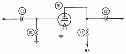
Fig. 3. An R-C--coupled grounded-cathode amplifier circuit.
The circuit in Fig. 3 is called a resistance-capacitance- coupled (R-C) circuit. A transformer-coupled circuit is given in Fig. 4. Its operation is similar to that of the circuit in Fig. 3. The transformer secondary and C1 are tuned so that only a very narrow band of frequencies will pass. Therefore, only the desired frequencies are coupled to the grid of the tube. The amplified signal appears at the plate and is coupled via T2 (which is tuned by C2 to the desired frequency) to the next stage.
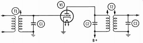
Fig. 4. A transformer-coupled amplifier circuit.
Another type of circuit is given in Fig. 5. Here the signal is coupled to the grid of the tube via C1--the same as in Fig. 3. However, here the similarity ends. Notice that the plate is connected directly to the B+ voltage source, so the signal will be bypassed to ground by the filter capacitors in the power supply. Also notice R2 and C2 connected to the cathode. In this circuit, called a cathode follower, the signal is developed across resistor R2 and coupled to the next stage by C2. No gain is accomplished in this circuit; in fact, there will be a slight loss. But, in certain applications the cathode follower has advantages over the amplifier circuit of Fig. 4.
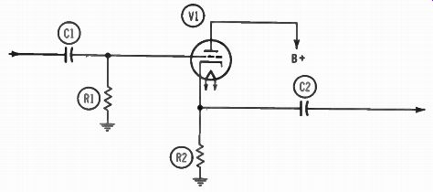
Fig. 5. A cathode-follower circuit.
Still another version of the triode amplifier is given in Fig. 6. This is called a grounded-grid amplifier. The signal is applied to the cathode, and the output is at the plate in this circuit. As you can see, the grid is not actually connected to ground as implied by the name. However, capacitor C1, connected between the grid and ground, serves as a by pass capacitor and removes any variations in the voltage which might occur at the grid.
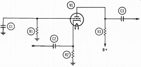
Fig. 6. A grounded-grid amplifier circuit.
Other Circuits
There are many variations in the basic circuits given in the foregoing. As explained in Section 5, often tetrode or pentode tubes are employed. Except for the added components for the screen circuit, operation is basically the same as for the triodes given here. Normally the signal is applied to the grid. The changes in the grid voltage caused by this signal increase or decrease the number of electrons which can flow through the tube from cathode to plate. Thus, the number of electrons flowing out the plate and through the plate load (i.e. the resistor or transformer winding connected to the plate) varies in step with the signal on the grid. This varying electron flow produces a varying drop across the plate load, and this drop is coupled to the next stage. Since a small change at the grid produces a much larger change at the plate, the signal is said to be amplified.
The foregoing is true no matter whether a triode, tetrode, or pentode tube is used. There are many special circuits which will generate their own signal, change the form of the applied signal, and perform many other functions. How these circuits operate is beyond the scope of this guide. Suffice it to say that the same basic idea of electrons flowing from cathode to plate, and the amount of this flow being affected by the elements between the cathode and plate, still applies.
Tube Voltages
All tube voltages are measured with respect to the cathode.
Often the cathode is connected to ground; at other times it is connected through a small-value resistor to ground. In the first instance, the actual voltage at the cathode is zero; in the latter, it will be a few volts positive. It makes no difference what the actual cathode voltage is--it could be -100 volts or +100 volts--as long as the voltage on the other elements is maintained in the proper relationship.
The grid is usually a few volts negative with respect to the cathode. The actual amount will vary with different tubes. Both the plate and the screen are positive with respect to the cathode. Normally this difference will be from 100 to 200 volts, but sometimes it is less and sometimes more.
Usually the plate will be slightly more positive than the screen grid, but sometimes the two voltages will be the same, and in certain instances, the screen will be more positive than the plate. The suppressor grid is usually connected to ground or to the cathode; hence, at most there will be only a few volts difference between it and the cathode.
BASIC TRANSISTOR CIRCUITS
Like tubes, transistors can be connected in three different ways-the common emitter, common base, and common collector. Also, since both PNP and NPN transistors are used, the number of variations is doubled. Now let's look at each of the basic transistor circuits and see how it operates.
The Common-Emitter Circuit
A common-emitter circuit using a PNP transistor is given in Fig. 7A, while the same circuit with an NPN transistor is given in Fig. 7B. Like its vacuum-tube counterpart- the grounded-cathode amplifier-the common-emitter circuit is the most popular. First look at Fig. 7A. The signal is coupled via C1 to the base of transistor Q1. R1 and R2 establish the proper operating voltages on the base, and R3 establishes the operating voltage on the emitter. The amplified signal appears across R4 and is coupled to the next stage via C3.
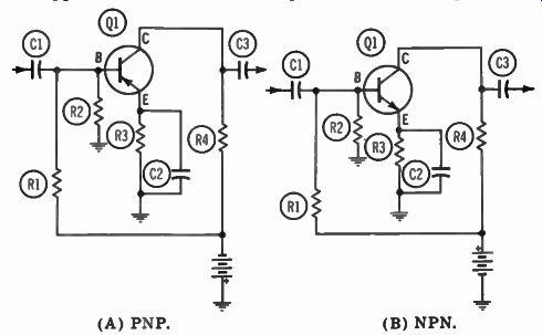
Fig. 7. Common-emitter circuits. (A) PNP. (B) NPN.
The circuit in Fig. 7B is the NPN version of the same circuit. Again, the signal is coupled to the transistor via C1, and the amplified version of the signal appears across R4 and is coupled via C3 to the next stage.
The only difference between the two circuits in Fig. 7 is the type of transistor and the way the battery is connected in the circuit. (The operating voltages will be discussed later.)
The Common-Base Circuit
The two circuits in Fig. 8 show the PNP and NPN versions of the common-base circuit. The input signal is coupled to the emitter of the transistor via C1. The amplified signal appears across R3 and at the collector of the transistor. Here it is coupled to the next stage via C3.
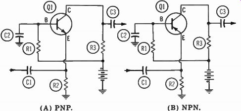
Fig. 8. Common-base circuits. (A) PNP. (B) NPN.
Resistor R1 establishes the correct operating voltage at the base. Note, however, that this resistor is bypassed by capacitor C2. Thus C2, by alternately storing and releasing electrons, removes any variations and maintains the base at a constant voltage. Since the voltage is constant as far as the signal is concerned, it is at ground potential. This is the same as for the grounded-grid tube-type amplifier discussed previously. As in Fig. 7, the two circuits in Fig. 8 are identical except for the type of transistor and the polarity of the battery.
The Common-Collector Circuit
The PNP and the NPN versions of the common-collector circuit are given in Fig. 9. The input signal is coupled by C1 to the base of transistor Q1, and the output signal appears across emitter resistor R3. Then it is coupled via C3 to the following stage. Resistors R1 and R2 establish the proper operating voltage at the base of the transistor. R4 performs the same function at the collector but, like the base of the previous circuit, the collector is bypassed by a capacitor (C2) . Hence, as far as the signal is concerned, the collector is at ground potential. Again, the only differences in the two circuits are the transistor type and the polarity of the battery.
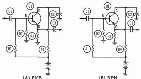
Fig. 9. Common-collector circuits. (A) PNP. (B) NPN.
Voltages
As we have pointed out in each of the basic circuits, the negative terminal of the battery is connected (through a resistor) to the collector of a PNP transistor, while for the NPN transistor the battery is reversed. Unlike a tube, in which electrons always flow in one direction (from cathode to plate), the electron flow through the two types of transistors is in opposite directions.
Electrons always flow from the negative terminal of a battery, through the circuit, to the positive terminal. In a PNP transistor electrons flow from collector to emitter; hence, the collector must be the most negative point. The base is maintained a few tenths of a volt negative with respect to the emitter. Therefore, the emitter has the most positive voltage of any of the elements.
The opposite is true of the NPN transistor. Here, the electrons must flow from the emitter to the collector. There fore, the emitter is the most negative point. The base is a few tenths of a volt positive with respect to the emitter, and the collector is the most positive point.
SUMMARY
The circuits discussed in this section are the basic amplifier circuits. In the next section, we shall see how these circuits are modified for use in actual radio receivers. The basic principles outlined in this section apply to all of the circuits-regardless of the refinements.
QUESTIONS
1. What is the purpose of a rectifier?
2. What is a passive circuit?
3. In which direction do electrons flow through a diode tube when the plate is negative with respect to the cathode?
4. What are the two types of transistors?
5. Which of the basic tube circuits produces a loss?
6. In which direction do electrons flow through an NPN transistor?
7. What element of the tube is used as the reference point for all tube voltages?
8. What are the three basic transistor circuits?
9. What are the three basic tube circuits?
10. From what terminal of a battery do electrons flow?