AMAZON multi-meters discounts AMAZON oscilloscope discounts
Most schematics follow the same general arrangement. The input is normally at the upper left-hand corner, and from here, the path is usually arranged in rows from left to right and from top to bottom. Starting at the input, you can trace your way through the individual circuits as if you were reading a guide. The best way to read a schematic is to analyze each stage, forming a mental image of what happens in it, and then see where its output goes. This is the input of the next "block" in the equipment. Continue through all the stages until you reach the output device (i.e., speaker, picture tube, indicator, etc.).
If this pattern is followed for any schematic, the operation of any equipment-whether it be a radio or TV receiver, transmitter, radar, or even a computer-should become apparent.
RADIO-RECEIVER SCHEMATIC ANALYSIS
The schematic of a typical five-tube AC-DC radio receiver is given in Fig. 1. Let's see just what information it contains.
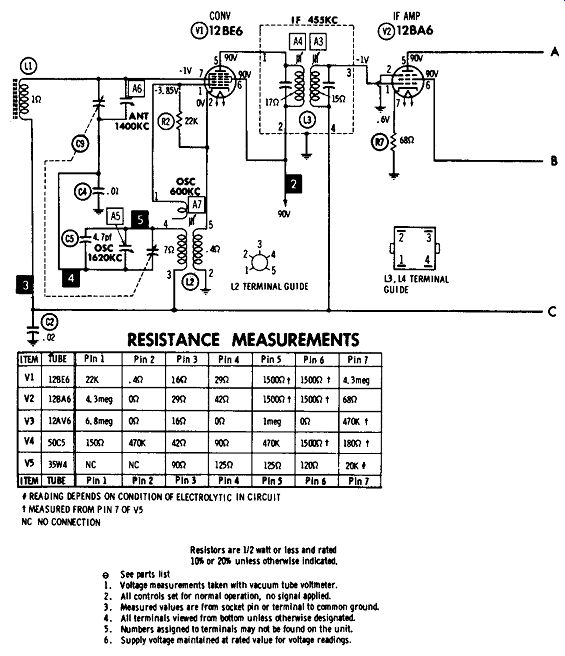
Fig. 1. Schematic of an AC-DC radio with phono.
The Signal Path
It is suggested that you refer to Fig. 1 as we follow the signal from tube to tube (stage to stage in electronics terminology) on its journey through the radio. The same general principles can then be applied to many other circuits.
The Converter--The first stage (tube) in most present day radios is the converter, which actually functions as an RF amplifier, oscillator, and mixer. The signal is first intercepted by loop antenna L1 in Fig. 1. The two variable capacitors connected across L1 tune the circuit to the frequency of the desired station. The signal is then connected to the grid (pin 7) of converter tube V1. Coil L2, the two variable capacitors (C9 and A5), capacitor C5, resistor R2, the grid (pin 1), and the cathode form the oscillator portion of the stage.
The signal from the oscillator and the one from the antenna are combined, or mixed, within the tube. The two original signals are still present at the output (the plate, pin 5) of the tube, but two more also appear. One is equal to the sum of the frequencies of the two original signals, and the other is equal to the difference between them. Both are exactly like the original antenna signal except in frequency.
Transformer L3 is "tuned" to accept this difference frequency, called the IF (intermediate frequency) and to pass it across the secondary to the next stage.
IF Amplifier--The next stage is the IF (intermediate-frequency) amplifier. The IF signal at the secondary of transformer L3 is connected to the grid (pin 1) of IF amplifier tube V2. Here the signal will be boosted, or amplified, by the time it reaches the plate (pin 5). From here it appears at the primary of transformer L4, and is coupled to the secondary, as before, for application to the next stage.
Detector, AVC, and Audio Amplifier--The signal from L4 is connected to pin 5 of dual-purpose tube V3. The element at pin 5 is a diode plate and, with the cathode (pin 2), operates like any diode tube. The remainder of the tube (pins 1, 2, and 7) forms a triode. (The other diode, pin 6, is connected directly to ground, so effectively it is not used in this circuit.) The signal applied to pin 5 undergoes a change by a process called detection. Here the carrier signal from the transmitter is removed and a signal which corresponds to the original one--music, speech, etc.--at the station appears across volume control R1. This is the audio-frequency signal (one whose frequency can be heard by the human ear). It is far too feeble to operate a speaker (although it could be heard from an earphone connected at this point). A portion (the amount depends on the volume-control set ting) of this audio signal is coupled to the grid (pin 1) of the triode section through the .005-mfd capacitor in PC1. Here, it is amplified by the tube and appears across the 470K resistor in component combination PC1, ready for coupling to the next stage.
Another voltage is also developed, at the bottom of R6.
Called the A VC (automatic volume control) voltage, it varies according to the strength of the signal received at the antenna. It is applied through L3 to the IF amplifier, and through L1 to the mixer stage to change the gain, or amount of amplification. Thus, if the signal becomes stronger or weaker (say, because of atmospheric conditions), the gain of the previous stages is automatically decreased or increased accordingly, to compensate for the change.
Audio-Output Stage--The signal across the 470K resistor (in PC1) is coupled via the .005-mfd capacitor ( also in PC1), to the grid (pin 2 or 5) of tube V4. Like the other stages, it amplifies the signal which appears at the plate and across transformer T1. The speaker (SP1) connected across the secondary of T1converts the amplified signal into sound.
Power Supply--Before any of the stages discussed in the foregoing can work, the proper voltages must be applied to them. This is the purpose of the components located in the lower-right corner of the schematic (Fig. 1). The line cord, which is plugged into a 117-volt AC outlet, is shown at the left. The next symbol is for an AC interlock, a special type of plug-and-socket arrangement that removes the line voltage from the receiver when the back is removed. When switch S1B is moved to the radio position, it connects one side of the line to the tube.
RF bypass capacitor C6 removes any high-frequency noise that might be present on the power lines and be passed into the receiver. The tap on the rectifier-tube filament allows a dial lamp to be connected between pins 4 and 6, although not used in this receiver. The 6.3 volts between these two points is just the proper amount for the lamp. The line voltage, minus the 6.3-volt drop between pins 4 and 6, is connected to the rectifier plate ( pin 5) . You will recall from the previous Section that a diode ( or any other tube) will conduct only when its plate is more positive than its cathode. The AC line voltage varies from positive to negative; hence, during the positive half-cycles the tube conducts and a pulsating DC is present at the cathode (pin 7). The two-section electrolytic capacitor (C1A and C1B) and resistor R5 smooth out these pulsations. Thus the voltage at the output is essentially DC. The symbols connected in a row and extending from pin 3 represent the filaments of the other tubes in the radio. This arrangement, called a series string, is most popular for the smaller home radios. The sum of the voltage requirements for all tubes is the same as the applied line voltage. Hence, by connecting them across the line in this manner, no separate transformer is needed to lower the voltage to the value required for each individual tube. The disadvantage is that, like the old-fashioned Christmas-tree lights, if one burns out it opens the circuit and they all go out.
In addition to the radio, the unit in Fig. 1 includes a phonograph. Notice that in either the radio or phono position the shorting bar on switch S1B will connect AC power to the rectifier tube. Closing switch S2 will cause power also to be applied to the phono motor Ml. Switch S1 is a two section switch; the other portion (S1A) is located below tube V3. In the radio position the output of the detector (pin 5 of V3) is connected to the volume control through the switch. In the phono position, the converter, IF amplifier, and detector portions are disconnected and instead the phono cartridge (M2) is connected to the volume control via S1A. C8 is an RF bypass capacitor.
Voltage and Current
In addition to the signal path, many more items are included on the schematic diagram. One is the voltage at each pin of every tube. This information comes in handy for troubleshooting the equipment. Notice that the voltages at the various points in the filament circuit are included in the power-supply portion of the schematic. Also included here is the total current flowing through the rectifier ( 56 ma, for milliamperes). The power rating of the equipment (28 watts at 117 volts) is given at the line cord. The notes below and to the left of the line cord state the conditions under which the voltage measurements were taken.
Other Information on Schematics
Many other items are included in Fig. 1, and each is useful in analyzing circuit operation or in troubleshooting.
For example, to the right of L2 is the drawing that shows the location of the terminals on the coil. These numbers are also included on the schematic symbols. The terminals on L3 and L4 are located below the drawing. Also given in Fig. 1 are the pin numbers of each element for each tube, and the connections to the resistance-capacitance component combination PC1.
Transformers and other components often have colored leads for identification. These are shown in Fig. 1 for audio-output transformer T1 and electrolytic filter capacitor C1.
The chart at the lower left gives the correct resistance reading, in ohms, from each tube pin to ground. Also given beside each coil on the schematic is its resistance (if over 1 ohm), since the easiest method of checking the condition of a coil is to measure its resistance.
Letter-and-number combinations A1 through A7, shown in the squares, are the alignment points for the receiver.
Adjustments are made here, according to the instructions, to tune each stage to the proper frequency.
TRANSISTOR RADIOS
Like its vacuum-tube counterpart, a transistor radio can also be broken down into a group of simple circuits. In the transistor-radio schematic of Fig. 2, for example, each transistor forms a block in the operation of the over-all unit.
The signal from the station is first received at antenna coil L1. The converter transistor (Q1) performs the same function as its vacuum-tube counterpart. L2 is the oscillator coil. The signals from the oscillator and antenna are mixed in this stage, and the IF (difference frequency) is coupled to the next stage via transformer L3. The signal enters transistor Q2 at the base (B), and the amplified signal appears at the collector (C) and across the primary of transformer L4. It is then coupled to the base of transistor Q3 ( another IF amplifier) via CS. The further amplified signal appears across the primary of L5. Crystal diode X2, connected to the secondary of L5, is the detector; it demodulates the IF signal, leaving the audio component at the variable arm of volume control R1. (This audio component corresponds to the original sound at the station.) From the volume control, the audio signal goes to the base of audio-amplifier transistor Q4, where it is amplified. It is then coupled directly to the base of transistor Q5. Here the signal is amplified and coupled via transformer T1 to the speaker ( SP1). The transistor receiver in Fig. 2 is designed to operate directly off the 117-volt power line. Here semiconductor rectifier X1 is used in place of the tube in Fig. 1. otherwise, the circuit operation is very similar to that described previously.
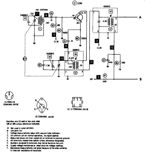
Fig. 2. A transistor radio.
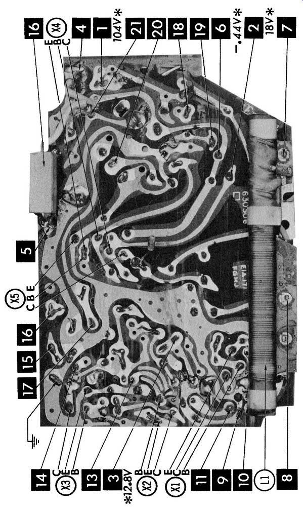
Fig. 3. Printed circuit used in the radio in Fig. 3.
The numbers 1 through 21 in the black boxes appear on the schematic and also in Fig. 3, a photograph of the chassis. Called CIRCUITRACE (a trade-name of Howard W. Sams & Co., Inc.) this system greatly aids in locating the various points on a printed-circuit board. By referring to the schematic and Fig. 3 simultaneously, technicians are saved tedious tracing of the printed wiring.
FROM SCHEMATIC TO CHASSIS
One of the most difficult problems a beginner faces is to locate, on the chassis, a component included in a schematic; or to look at a schematic and construct the circuit. Unfortunately, as you saw in Section 1, the actual chassis does not look like the schematic. In fact, in the schematic a resistor may be shown next to a tube element, but may be at the other side of the chassis. The reason is that a schematic can show electrical connections only, but a component must also have some means of mechanical support.
Terminal strips are often included on the chassis, and the terminals utilized for connecting between two points. Not all pins are used for internal connections on all tubes, but the tube socket will have terminals for each pin. For example, for mechanical support, one end of the resistor may be connected to an unused tube-socket terminal, which is then connected by a wire at the other end of the circuit.
If you have a photograph or pictorial drawing like the ones shown in Section 1, a component is easy to locate. But the component can still be located, even if only the schematic is available. Just look for a familiar nearby point in the circuit. (Tube pins are usually the most convenient points.) Then see what components are connected between this point and the desired component. Next find this point on the schematic, and follow any wire connected to it. Be sure to trace out all leads connected to any tie points (terminal strips or unused tube pins). If you encounter a component not connected between the wanted one and the starting point, go back and try a different route. While such hit-and-miss tracing sounds tedious, with a little practice it soon becomes easy and fast. Remember: the fact that a component is connected to a tube-socket terminal doesn't mean there is an internal connection to the tube. This connection may be there for mechanical support only.
OTHER TYPES OF EQUIPMENT
No matter how complex, the schematic of any piece of electronic equipment can be broken down into individual stages, as you did in this Section. Then by following the connections between stages you will be able to fit the blocks together and in this way determine the over-all operation of the circuit.
QUIZ
1. Where is the input normally located on a schematic?
2. What three functions are performed by the converter stage?
3. What additional aid in locating transformer leads is often included on a schematic?
4. What is the purpose of the AVC voltage?
5. How does the IF signal differ from the signal received from the station?
6. What is the best way to analyze a schematic?
7. What type of signal appears across the volume control?
8. What is the disadvantage of connecting all tube filaments in series?
9. Does an earphone or a speaker require more power for operation?
10. What is the purpose of an RF bypass capacitor?