AMAZON multi-meters discounts AMAZON oscilloscope discounts
When a circuit is closed, a complete path is provided over which electrons can flow. Conversely, when open no path exists and hence the circuit is inoperative. Some means must be provided to open or close many of the circuits in electronic equipment. Each of the devices discussed in this Section will perform this switching function.
SPST SWITCHES
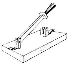
Fig. 1. A single-pole, single throw knife switch.
The simplest switch is the knife switch illustrated in Fig. 1. When the arm moves down, it engages the clips at the end and completes the circuit to which it is connected. Such a device is called a single-pole, single-throw switch (abbreviated SPST). It can make connections for only one line, and at only one point. The symbols for SPST switches are given in Fig. 2. All look alike except B, differing only in the arrow- heads (which indicate the movable contact) and the small circles (which indicate the connection points). Other types of construction can be used for the SPST switch, such as the familiar on-off switch for controlling our house lighting. The toggle switch, slide switch, and radio or TV on-off switch (which is activated by rotating or pulling and pushing a shaft), are all SPST units and are identified by the symbols in Fig. 2.
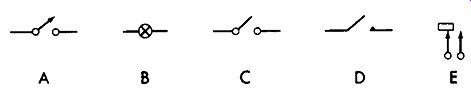
Fig. 2. Single-pole, single-throw switch symbols.
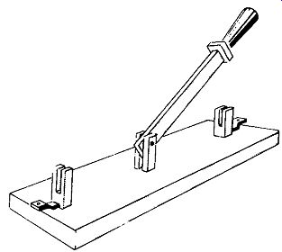
Fig. 3. A SPDT knife switch.
SPDT SWITCHES
The knife switch shown in Fig. 3 can be used to connect the center terminal to either outside terminal. It still makes connections for only one line at a time, but to either point.
Called a single-pole, double-throw (abbreviated SPDT) switch, it appears in many forms-toggle, slide, rotary, and pushbutton, to name a few. The symbols for the SPDT switch (Fig. 4) are the same as those of the SPST except for the added connection.
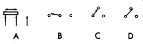
Fig. 4. SPDT switch symbols.
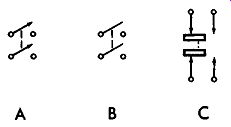
Fig. 5. DPST switch symbols.
DOUBLE-POLE SWITCHES
To control two separate circuits with a single switch, a double-pole unit is needed. It comprises two sections, each like the single-pole type shown previously, that are mechanically but not electrically connected. For instance, a double-pole, single-throw (DPST) knife switch consists of two blades, each of which can be connected to one set of terminals. The two blades are connected, or ganged, together (by an insulating material) so that when one is moved, the other automatically follows. Fig. 5 shows the symbols used to denote DPST switches. The dashed line indicates that the two arms are mechanically but not electrically connected.
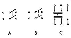
Fig. 6. DPDT switch symbols.
By adding another set of terminals to the two-bladed knife switch so that the two mechanically-connected blades make contact in either of two positions, it becomes a double-pole double-throw (DPDT). Fig. 6 shows the symbols for this type.
WAFER SWITCHES
The wafer switch shown in Fig. 7 is very popular for making connections to more than one point. Fig. 8 shows the symbols for one type. Here, the center terminal can be connected to any one of the six points around it. Often the wafer is constructed as shown in Fig. 9. One contact around the edge is longer so that it always makes connection with the circular ring in the center. Notice that one point on the ring extends out farther than the rest. As the switch is rotated, this point will be connected to each contact, one after another, around the outside. This, then, is actually a single pole, 12-throw switch. Fig. 10 shows the most common symbol for it. The arrows extending from the small circles represent the contacts around the outside. The longest arrow is the longest contact. The ring is deliberately drawn so that it does not touch the arrowheads except at the long contact and at the point of extension on the ring. As the switch is rotated, this extension contacts each arrowhead in turn. The symbol is usually pictured as being viewed from the shaft end, and the terminals are numbered clockwise, as shown in Fig. 10. If the wafer is being pictured from the rear, the numbers will be numbered counterclockwise, of course.
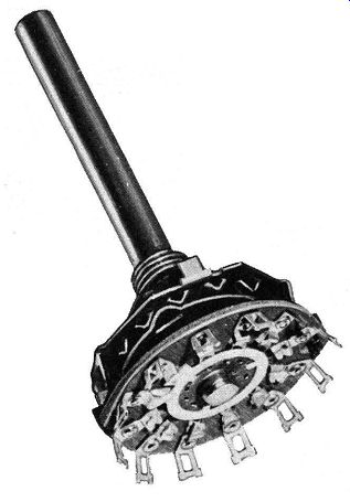
Fig. 7. A typical wafer switch.
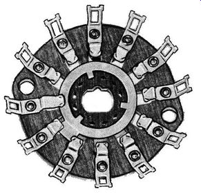
Fig. 9. A typical wafer.
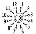
Fig. 10. A single-pole, 12-position wafer-switch symbol.

Fig. 8. A single-pole, 6-position switch symbol.
A single-section wafer switch can be used when two or more circuits must be switched in and out at the same time.
By making some points wider on the rotating ring, certain connections can be made between them and the stationary contacts. The ring may also be broken instead of solid so that one half will serve some of the stationary contacts, and the other half the remainder. For instance, symbol A in Fig. 7 11 shows a switch in which terminals 2 and 3 are connected to terminal 5, and terminals 7 and 9 to terminal 11. The arrow at the center indicates the direction the center portion moves when the switch is rotated. Rotating the switch one position will connect terminals 3 and 4 to terminal 5, and terminals 8 and 10 to terminal 11. Any number of connections can be made by such switches, each depending on the construction of the shorting ring. Two other possibilities are shown in symbols B and C.
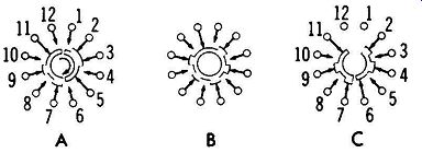
Fig. 11. Wafer-switch symbols.
Another method of showing a wafer switch, especially for TV tuners, is shown in Fig. 12. Here the switch is laid out horizontally. The bar below the row of arrowheads represents the inner shorting ring (which for illustrative purposes has been straightened out and broken). The jagged lines at the ends of the bar signify the broken bar. In the actual switch, the two ends are connected at this point. As the switch is rotated, the bar moves along and makes connections to the various contacts. The principal advantage of depicting the switch in this manner is that coils, which are usually connected across the various contacts, can be shown more easily.
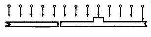
Fig. 12. Another method of representing a wafer switch.
Several wafer sections are often connected to a single shaft. Thus, rotating the shaft will change the connections at each section. While most of the wafer switches shown in this Section have 12 positions, many have from 18 to 24 or more. The symbols used by some companies will vary slightly.
For example, the numbers representing the terminals may be placed within the circles. Nevertheless, all symbols will be very similar to the ones shown here.
PUSH-BUTTON SWITCHES
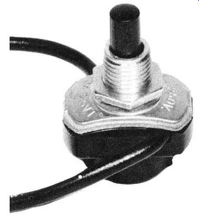
Fig. 13. A push-button switch.
Sometimes the general switch symbol in Fig. 2 is utilized for the familiar push-button switch of Fig. 13. Symbol A in Fig. 14 is more widely used, however. The vertical portion represents the button; when pushed, it moves the bar down to make connection across the contacts, represented by the two circles. The same switch is also shown by symbol B. Here, the arrowheads represent the contacts. Both symbols A and B represent a normally open switch. If the switch is normally closed, pushing the button will open the circuit.
Symbols C and D denote this type of switch.
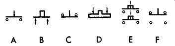
Fig. 14. Push-button switch symbols.
A push-button switch can also be of the double-pole variety, as shown by symbol E. Here, pushing the button closes two circuits. Symbol F represents a switch which opens one circuit and closes another when the button is pushed.
Code Letters
Switches may be designated by several different letters.
The more common are S, SW, M, and E. In addition, the letters WS are sometimes used to indicate a wafer switch.
RELAYS
All the switches discussed previously were actuated by either rotating or sliding a knob, pushing a button, or some other mechanical movement. A relay is an automatic switch, which may or may not require a physical action to be activated. For instance, a relay could be connected into a photo electric-cell circuit. When light falls on the cell, more current will flow through the tube and a relay in its plate circuit will close.
A typical relay consists of a coil of wire wound around an iron core, and two contacts. The relay becomes energized as current flows through the coil and causes its core to act as an electromagnet. One of the contacts, being movable, is attracted by this electromagnet, and in moving toward it, touches the other (stationary) contact, completing the circuit. When current through the coil decreases below a certain amount, a spring returns the contact to its original position.
Just as there are many types of switches, there are also re-lays of many types and shapes to fit a multitude of applications. A few of them are pictured in Fig. 15.
The symbol for a simple relay is given at A in Fig. 16.
The bar at the top of the symbol is the movable contact, and the arm with the arrowhead is the stationary one. The relay coil is represented by a wire wrapped around a rectangle (representing the core). The dashed line (sometimes omitted) signifies that the core attracts the movable element.
Another method of showing the same relay is by symbol B; here, the regular iron-core coil symbol is used to represent the relay coil.
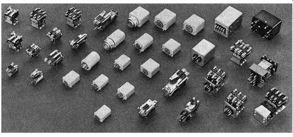
Fig. 15. Various types of relays.
The relays in symbols A and B are both single-pole, single throw units. All types of relays are available, however. For example, symbol C shows a single-pole, double-throw unit.
The movable contact completes the circuit to the upper stationary contact. This is called the de-energized position (no current flowing through the coil). When current does flow, the movable contact is pulled down, opening the upper circuit and closing the lower one.
To simplify circuit layout, the connections to the relay are sometimes brought out different sides, as shown in D. The circuit between the two contacts in this relay is normally closed. When energized, the movable contact is pulled down and opens the circuit. Sometimes the letters NC (for normally closed) or NO (for normally open) are placed beside the contacts on the schematic to signify the de-energized position.
A single relay coil may operate more than one movable arm at the same time. Symbol E depicts a two-section relay.
The top part is a single-pole, single-throw section which is normally closed. The bottom part is a single-pole, double throw unit which is normally connected to the upper contact.
A somewhat different way of representing a relay is given at F.
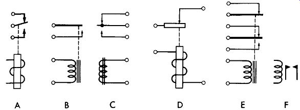
Fig. 16. Relay symbols.
There are innumerable possibilities in the types of relays, but their operation is obvious from examining the contacts.
Just remember that the relay is normally shown in its de energized position, and that energizing the relay will cause the position of the bar to move toward the coil.
The most common letters for designating relays on schematic diagrams are K, RE, RL, M, and E.
QUIZ
1. What is the basic purpose of a switch?
2. What type of switch is most commonly used as the on-off switch for a radio?
3. What type of switch does the abbreviation SPDT indicate?
4. What is the purpose of the switch in Question 3?
5. What is a relay?
6. What does a dashed line between two points on a switch symbol indicate?
7. What is the purpose of the coil in a relay?
8. What are three of the code letters used to designate switches on schematics?
9. Draw the symbol for a double-pole, double-throw switch.
10. Draw the symbol for a single-pole, double-throw relay.