AMAZON multi-meters discounts AMAZON oscilloscope discounts
The term thyristor refers to a broad family of semiconductor devices used primarily for power control. Thyristors are basically fast-acting electronic switches.
Common members of the thyristor family include silicon controlled rectifiers, unijunction transistors, triacs, diacs, and (strangely enough) neon tubes.
Silicon controlled Rectifiers
Silicon controlled rectifiers (SCRs), which are probably the most common of all thyristors, are three-lead devices resembling transistors. The three leads are referred to as the gate, cathode, and anode. An illustration of SCR construction, lead designation, and electrical symbol is given in Fig. 1.
An SCR will allow current to flow in only one direction. Like a diode, the cathode must be negative, in relation to the anode, for current flow to occur. However, forward current flow will not begin until a positive potential, relative to the cathode, is applied to the gate. Once current flow begins, the gate has no more control of the SCR action until it drops below its designated holding current.
One method of stopping the forward current flow, in a conducting SCR, is to reverse-bias it (cause the cathode to become positive relative to the anode). Another method is to allow the forward current flow to drop below the SCR's holding current. The holding current is a manufacturer's specification defining the minimum current required to hold the SCR in a conductive state.
If the forward current flow drops below the specified holding current, the SCR will drop out of conduction. When this happens (as a result of either a voltage polarity reversal or a loss of minimum holding current), control is again returned to the gate, and the SCR will not con duct (even if forward-biased) until another positive potential (or pulse) is applied to the gate.
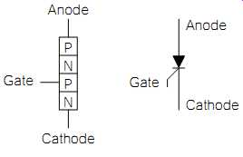
FIG. 1 SCR construction and electronic symbol.
Like a transistor, the SCR is considered a current device because the gate current causes the SCR to begin to conduct (if forward-based). Also, the forward current flow is the variable that maintains conduction, once the SCR is turned on by the gate current.
Because SCRs can be turned off when they are reverse-biased, they are very commonly used in AC power applications. Because AC power reverses polarity periodically, an SCR used in an AC circuit will automatically be reverse-biased (causing it to turn off) during one-half of each cycle. During the other half of each cycle, it will be forward-biased, but it will not conduct unless a positive gate pulse is applied. By control ling the coincidental point at which the gate pulse is applied together with a forward-biasing half-cycle, the SCR can control the amount of given power to a load during the half-cycles it is forward-biased.
Consider the circuit shown in Fig. 2. As long as SW1 remains open, RL will not receive any power from the AC source because the SCR will not conduct during either half-cycle. If SW1 is closed (providing a continuous positive potential to the gate), the load will receive half of the available power from the AC source. In this condition, the SCR acts like a diode, and conducts current only during the half-cycles when it is for ward-biased. (Resistor RG is placed in the gate circuit to keep the gate current from exceeding the specified maximum.)
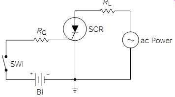
FIG. 2 Demonstration of SCR operating principles.
If it were possible to rapidly turn SW1 on and off, so that the SCR received a gate pulse at the "peak" of each forward-biasing half-cycle, the SCR would only conduct for "half" of the half-cycle. This condition would cause the load to receive one-fourth of the total power available from the AC source. By accurately varying the timing relationship between the gate pulses and the forward-biasing half-cycles, the SCR could be made to supply any percentage of power desired to the load, up to 50%. It cannot supply more than 50% power to the load, because it cannot conduct during the half-cycles when it is reverse-biased.
There are several important points to understand about the operation of this simple circuit. First, once the SCR has been turned on by closing S1, it cannot be turned off again during the remainder of the forward biasing half-cycle. As long as the SCR is conducting a current flow higher than its minimum holding current, the gate circuit loses all control.
Second, before the SCR receives a gate pulse and begins to conduct, there is virtually no power consumption in the circuit; it looks like an open switch. Once the SCR begins to conduct, virtually all of the power is delivered to the load.
An SCR wastes very little power when controlling power to a load, because it functions in either of two states: ON (looking like a closed switch), or OFF (looking like an open switch). A closed switch might have a high amplitude of current flow through it, but it poses no opposition (resistance). Therefore, the voltage drop across a closed switch is virtually zero. Because power dissipation is equal to current times voltage (P = IE), when the voltage is close to zero, so is power dissipation. In contrast, an open switch might drop a high voltage, but does not allow current flow.
Again, it becomes irrelevant how high the voltage is, if there is no cur rent flow; power dissipation is still zero.
To understand the importance of efficient power control, consider another method of varying power to a load. FIG. 3 illustrates a circuit in which a rheostat is used to vary the power delivered to a 50 ohm load (RL ).
The rheostat is adjustable from 0 to 50 ohms. When it is adjusted to 0 ohm, it will appear to be a short and the entire 120-volts AC source will be dropped across RL. The power dissipated by RL can be calculated as follows :
P __ _ _ 288 watts 14400
_ 50 1202
_ 50 E2
_ R
The power dissipated by the rheostat will be
P __ _ 0 (0) 2
_ 0 E 2
_ R
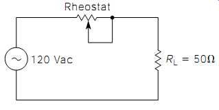
FIG. 3 Rheostat power control circuit.
If the rheostat is adjusted to present 50 ohms of resistance, the voltage dropped by the rheostat will be equal to the voltage dropped by RL.
Therefore, 60 volts AC will be dropped by both. Because they are both equal in voltage drop and resistance, the power dissipation will also be equal in both. Therefore, under these circumstances, the power dissipation of either is
P __ _ _ 72 watts 3600
_ 50 602
_ 50 E2
_ R
Because the purpose of the circuit shown in Fig. 3 is to control the power delivered to the load (RL ), all of the power dissipated by the rheostat is wasted. In the previous example, the efficiency of the power control is 50%. At different settings of the rheostat, different efficiency levels occur; but it is obvious that this level of waste is unacceptable in high power electrical applications.
A disadvantage of using a single SCR for power control, as illustrated in Fig. 2, is that it is not possible to obtain full 360-degree control of an AC waveform (only 180 degrees, that is, the forward-biasing half-cycle, can be controlled). To overcome this problem, two SCRs might be incorporated into a circuit for full-wave power control.
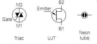
FIG. 4 Additional thyristor symbols.
The Triac
Another member of the thyristor family, the triac can be used for full wave power control. A triac has three leads designated as the gate, M1, and M2. Triacs are triggered on by either a positive or negative pulse to the gate lead, in reference to the M1 terminal. Triacs can also conduct current in either direction between the M1 and M2 terminals. Like an SCR, once a triac has been triggered, the gate loses all control until the current flow through the M1 and M2 terminals drops below the manufacturer's specified holding current. Triacs are considered current devices. The electrical symbols used for triacs are illustrated in Fig. 4.
The principle of efficient power control is essentially the same for the triac as it is for the SCR. Because a triac operates in only two modes (ON or OFF), full-wave power control can be obtained without appreciable power losses in the triac itself. The primary advantage of a triac is its capability of being triggered in either polarity, and controlling power throughout the entire AC cycle.
Triacs are commonly used for smaller power control applications (light dimmers, small DC motors and power supplies). Unfortunately, triacs have the disadvantage of being somewhat difficult to turn off (especially when used to control inductive loads). Because of this problem, SCRs (rather than triacs) are used almost exclusively in high-power applications.
Unijunction Transistors, Diacs, and Neon Tubes
So far in this section, you have examined the theoretical possibility of controlling power with SCRs or triacs. If you could vary the gate trigger pulse timing relative to the AC cycle (this is called varying the phase angle of the trigger pulse), you would have an efficient electronic power control tool. Obviously, it would be impossible for a human to turn a switch on and off at a 60-hertz rate to provide trigger pulses for power control.
Unijunction transistors, diacs, and neon tubes are commonly used to accomplish this function. (The neon tube is not actually a member of the thyristor family, but its function is identical to that of the diac.
Some equipment still uses neon tubes for triggering, because they serve a dual purpose as power-on indicators.)
Like the transistor, the unijunction transistor (UJT) is a three-lead device.
The three leads are referred to as the emitter, B1, and B2. The schematic symbol for UJTs is given in Fig. 4. Unlike the previously discussed SCR and triac, the UJT is a voltage device. When the voltage between the emitter and B1 leads reaches a certain value (a ratio of the applied voltage between the B1 and B2 leads, and the manufactured characteristics of the UJT), the resistance between the emitter and B1 decreases to a very low value.
Contrastingly, if the voltage between the emitter and B1 decreases to a value below the established ratio, the resistance between the emitter and B1 increases to a high value. In other words, a UJT can be thought of as a voltage breakdown device. It will avalanche into a highly conductive state (between the emitter and B1 leads) when a peak voltage level (expressed as Vp ) is reached. It will continue to remain highly conductive until the voltage is reduced to a much lower level called the "valley voltage" (Vv ).
Firing circuits are electronic circuits that vary the amplitude and phase of an AC trigger voltage applied to the gate lead of an SCR (or other thyristor). Using a combination of amplitude adjustment and phase-shifting techniques, the Vp level (resulting in UJT voltage break down) can be made to occur precisely and repeatedly at any "phase angle relative to an AC power waveform applied to a triac or SCR." The conductive breakdown characteristics of the UJT are used as a means of providing the gate trigger pulses to "fire" the SCRs or triacs. Therefore, the SCRs or triacs can be repeatedly fired at any point on the AC wave form, resulting in full-wave (0 to 100% duty cycle) power control.
Another voltage breakdown device is the diac. Because diacs are special-purpose diodes, their operational description and symbols have already been discussed in Section 7. Diacs are simply the solid-state replacement for neon tubes. The schematic symbol for neon tubes is given in Fig. 4. Neon tubes and diacs are devices which will remain in a nonconductive state until the voltage across them exceeds a breakover voltage (or ionization voltage in the case of neon tubes). At breakover, they will become conductive and remain so until the voltage across them drops below a holding voltage (a much lower voltage than the breakover voltage), at which time they will become nonconductive again.
Building a Soldering Iron Controller
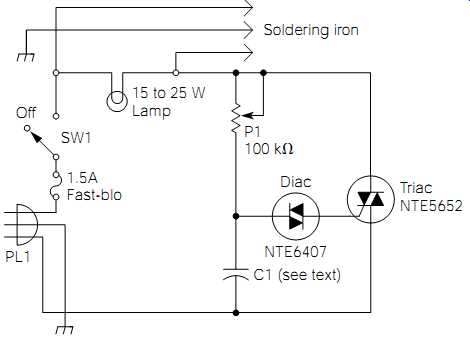
FIG. 5 A soldering-iron controller.
Soldering irons are available in many power ranges. The smallest sizes, around 15 watts, are recommended for very small and precise work, such as surface-mount-component (SMC) work. Medium sizes, about 30 watts, are recommended for most general electronic work, including PC board soldering. Larger sizes, from 60 watts and up, are for large soldering jobs, such as making solder connections to large bus bars or stud-mount diodes.
If you run into situations where you need to do a variety of different types of soldering, there are several solutions. The obvious solution is to buy several different types of soldering irons. Another solution is to buy a soldering station, with an automatic tip temperature regulator (starting at about $100.00). A good middle-of-the-road solution is to buy a 60-watt soldering iron, and use it with the circuit illustrated in Fig. 5. In addition to being a useful and convenient tool, this circuit will help illustrate most of what has just been discussed concerning thyristors and power control.
Referring to Fig. 5, the incoming 120-volt AC power is applied across the triac through the load (lightbulb and soldering iron, in parallel).
Assuming SW1 is turned on at the instantaneous point in time that the AC voltage is at zero, the triac is off (nonconductive). As the AC voltage begins to increase through a half-cycle (the polarity is irrelevant because the diac and triac are both bilateral in operation), all of the AC voltage is dropped across the triac because it looks like an open switch.
Similarly, the same voltage is dropped across the firing circuit, or trigger circuit (P1, the diac, and C1), because it is in parallel with the triac.
C1 will begin to charge at a rate relative to the setting of P1. As the AC half-cycle continues, C1 will eventually charge to the specified breakover voltage of the diac, causing the diac to avalanche, and a current pulse (trigger) to flow through the gate and M1 terminals of the triac.
This trigger pulse causes the triac to turn on (much like a closed switch), resulting in the remainder of the AC half-cycle being applied to the load (lamp and soldering iron). When the AC power has completed the half-cycle and approaches zero voltage (prior to changing polarity), the current flow through the triac drops below the holding current and the triac returns to a nonconductive state. This entire process continues to repeat with each half-cycle of the incoming AC power.
There are several important points to understand about the operation of this circuit. The diac will reach its breakover voltage and trigger the triac at the same relative point during each half-cycle of the AC wave form. This relative point will depend on the charge rate of C1, which is controlled by the setting of P1. In effect, the setting of P1 controls the average power delivered to the load. P1 can control the majority of the AC half-cycle because C1 also introduces a voltage-lagging phase shift.
Without the phase shift, control would be lost after the peak of the AC power cycle was reached. Throughout the entire power control range of this circuit, the power wasted by the triac is negligible, compared to the power delivered to the load.
PL1 is a standard 120-volt AC three-prong plug. If you build this project in an aluminum project box, the ground prong (round prong) should be connected to the aluminum box (the chassis in this case). For safety reasons, the 120-volt AC hot lead should also be fuse-protected. P1 is mounted to the front panel of the project box for easy access.
I used a flat, rectangular aluminum project box large enough to set the soldering iron holder on. I also connected the soldering iron internally to a phenolic solder strip with a strain relief to protect the cord.
This, of course, is a matter of opinion. You might want to wire the circuit to a standard 120-volt AC socket for use with a variety of soldering irons.
The triac, diac, and C1 can be assembled on a small universal perf board or wired to a phenolic solder strip.
The 15- to 25-watt lamp is a standard 120-volt AC incandescent light bulb of any style or design you like (it might also be any wattage you desire, up to 60 watts). It is mounted on the outside front panel of the project box and serves several useful indicator functions. First, it indicates that the power is on and that the circuit is functioning. Second, with a little practice, the brightness of the bulb is a good indicator of about how much power you are applying to the soldering iron. For example, if you're using this circuit with a 60-watt soldering iron, and you adjust P1 until the bulb is about half as bright as normal, you're supplying about 30 watts of power to the tip. Third, the lightbulb makes a good reminder to turn off the soldering iron when you're finished working. (I can't count how many times I have come into our shop and found the soldering iron still turned on from the previous day.) The best value for C1 will probably be about 0.1 uF. After building the circuit so that it can be tested using the lightbulb as the load, try a few different values for C1, and choose the one giving the smoothest operation throughout the entire power range. C1 must be a nonpolarized capacitor rated for at least 200 volts.
In addition to controlling the power delivered to a soldering iron, this circuit is a basic light-dimmer circuit. You might use it to control the power delivered to any "resistive" load up to about 150 watts. For control ling larger loads, you will need to use a larger triac and, depending on the triac, you might need to use different values for P1 and C1. For con trolling large loads, it's also a good idea to place a varistor (MOV) across the incoming 120-volt AC line (such as an NTE2V115).
Circuit Project
The theories and postulations are done. Now's the time for applications and fun!
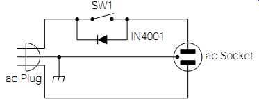
FIG. 6 Simple soldering iron power control.
An Easier Way?
They don't get any simpler than this: a very simple soldering iron power control as shown in Fig. 6. This circuit inserts a diode (with SW1 open) in series with the soldering-iron heating element. The diode will block one-half of the incoming AC voltage to the heating element, resulting in a power decrease.
Although it would seem logical that the soldering iron would operate at half-power with the diode in the power circuit (that is, a 60-watt iron would become a 30-watt iron), it is not quite that simple. The type of wire universally used in resistive heating elements is called nichrome.
Nichrome, like most resistive substances, has a positive temperature coefficient; as it becomes hotter, its resistance value goes up. When a resistive heating element designed for a 120-volt AC application (such as in a soldering iron) experiences a decrease in applied power, its temperature goes down, resulting in a proportionate decrease in resistance. This decrease in resistance has the effect of causing the wire to dissipate more "power per volt" than it did at the rated voltage.
The circuit illustrated in Fig. 6, if used in conjunction with a 60 watt soldering iron, would decrease its operational power down to about 40 watts. In reality, this would handle the vast majority of soldering jobs you will encounter. If you used this circuit with another soldering iron rated at 30 watts, it would decrease it down to about 18 watts (just about right for SMC work). In other words, two soldering irons (a 60-watt and a 30-watt), two general-purpose diodes, and two switches will provide you with the full gamut of soldering iron needs. One additional benefit- using a 50- or 60-watt soldering iron with the diode in the power circuit (and placing the wattage at about the optimum point for general-purpose electronic work) will cause the heating element to last about 40 times longer, and will thus increase tip life.
By the way, placing a general-purpose diode in series with incandescent (but not fluorescent!) lightbulbs will cause the lightbulbs to last about 40 times longer. The disadvantage resulting from this is the lower quantity and efficiency of the light produced.
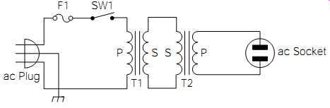
FIG. 7 General-purpose isolation circuit.
Isolation
FIG. 7 shows how to construct a simple isolation transformer for your electronics bench. Typically, isolation transformers are needed when testing line-powered equipment with line-powered test equipment.
For example, referring back to Fig. 5, suppose you wanted to observe the waveshape across the parallel circuit of the soldering iron and lamp with a line-powered oscilloscope. You connect the ground and scope probe across the lamp, turn on SW1, and "boom"-the fuse blows and the triac might be destroyed. What happened? For safety reasons, the ground (common) lead connections on most line-powered test equipment are connected to earth ground. Looking at Fig. 5, imagine the results of connecting earth ground to either side of the lamp/soldering iron connections. From a problematic viewpoint, there are several possibilities: two possibilities of how PL1 is wired (correct and incorrect), and many possibilities of how the scope can be connected. Out of these possibilities, three would result in improper operation, or destroyed components.
For example, if the iron controller's power cable were connected with the black wire going to the fuse (which is standard, safe, and correct), and the scope "common" probe was inadvertently touched to that part of the circuit (fuse, SW1, or that side of the lamp), then a direct short to ground would exist! If the probe connection was made to the cable side of the fuse, a catastrophic short would occur, hopefully blowing the fuse or breaker at the main box. If the connection were made beyond the fuse, this short could blow either the main fuse, the controller fuse, or both.
If the controller were isolated from the main power line, by using the isolation transformer, neither of the lines (black or white) going to the controller have any continuity to ground. Remember, in household wiring, the white wire is called the neutral, and it is kept at "ground" potential. The black and red wires are hot. Without the isolation provided by the transformer, the common scope probe, which is connected to earth ground and neutral (through the house wiring) and attached to the hot side of the controller, would present a dead short. For this reason, among others, isolation transformers are handy to have around.
In Fig. 7, T1 and T2 are any two "identical" power transformers, with appropriate ratings for the desired application. For example, assume that T1 has a secondary rating of 25 volts at 2 amps. It is, therefore, a 50-V A (volt-amp) transformer (25 volts x 2 amps= 50 VA). To calculate the maxi mum current rating of the primary, simply divide the volt-amp rating by 120 volts (intended primary voltage). This comes out to a little over 410 milliamps. The primary and secondary of any individual power transformer will always have the same volt-amp rating.
If you decided to use two such transformers for the isolation circuit, the primary of T1 would be connected to the line (120 volts AC). The secondary of T1 would be connected to the secondary of T2, whose primary would be the output. In other words, the function of the first transformer is to convert 120 volts AC down to 25 volts AC (step-down application), and the second transformer converts 25 volts AC back up to 120 volts AC (step-up operation). This "conversion from the original" and "conversion back to the original" process is the reason why both trans formers must be identical.
As explained earlier, 410 milliamps is the highest current load that can be drawn from T2's "intended primary" under ideal conditions. However, there are losses in power transformers, and, in this case, the losses are doubled. Therefore, it is necessary to derate T2's primary maximum cur rent value by 10%. Consequently, the maximum current output from this hypothetical isolation circuit will be only about 370 milliamps--a little too small for most general-purpose isolation requirements.
If you decide to build this type of isolation circuit for your bench, you'll probably want to use transformers with significantly higher volt-amp ratings. Unfortunately, it soon becomes apparent that power transformers in the 400- to 500-VA range are expensive, but so are isolation transformers. However, some "odd" value industrial transformers with high VA ratings can be purchased very inexpensively from many surplus electronic dealers. Just make sure that they are not ferroresonant transformers, or power transformers intended for use with 400 hertz AC power.
Latch Circuit
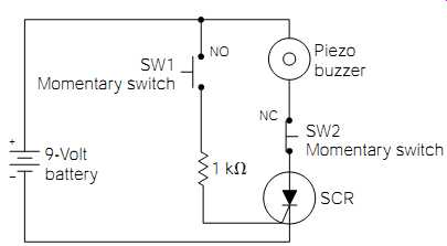
FIG. 8 SCR latch circuit.
FIG. 8 is an SCR latch circuit. When assembled as illustrated, depressing the "normally open" momentary switch (SW1) provides a positive gate pulse (relative to the cathode) and fires the SCR. Once conducting, the gate has no more control over the SCR, and it continues to conduct, powering the piezo buzzer, until the cathode/anode current flow is interrupted by depressing the "normally closed" momentary switch (SW2). Because the cathode/anode current flow drops below the holding current of the SCR (it actually drops to zero), control is returned to the gate, and the SCR will not conduct again until SW1 is depressed.
A circuit of this type is called a latch circuit. (The electromechanical counterpart of this circuit is a latching relay.) Just about any commonly available SCR can be used. The piezo buzzer can be substituted for almost any type of load that you need to be latched. There are many, many applications for such a circuit, but I would like to describe one that I had a lot of fun with.
I mounted this circuit in a small black box, using a 9-volt transistor battery as the power source. The piezo buzzer is commonly available in any electronics parts store. The buzzer was mounted close to the front of the box, where speaker holes were drilled. SW2 was located inside the project box. I mounted it in a lower back corner, so that the only way it could be depressed was to use a straightened paper clip through an almost invisibly small hole drilled through the back of the box. SW1 was mounted to the front plate with a large, red, plastic knob. Underneath the SW1 push button, I arranged stick-on letters to read "Do not push." You can probably guess the rest.
If the box is left in an obvious place, it will drive many people crazy, until they see what happens when the button is pressed. After their curiosity gets the better of them and they press the button, the piezo buzzer sounds off, and there isn't any apparent way to stop it.
After building this box, user discretion is advised! After playing this joke on a person lacking a really good sense of humor (while the buzzer was still sounding), I made the mistake of saying he could never figure out how to stop it. He promptly dropped it on the floor, and stomped on it with a large, silver-tip boot. I stood corrected.
Oscillator
The circuit illustrated in Fig. 9 is a UJT oscillator. UJTs make good oscillators for audio projects, and they have some distinct advantages over astable multivibrators. They are easier to construct, and require the use of only one UJT. Also, the output is in the form of a "sawtooth" wave, which provides more pleasing audio harmonics than square waves. (This circuit will be used as a foundation for later projects in this guide.) UJT oscillators do have a drawback. Their usable audio output, which is taken across the capacitor, has a very high impedance. Therefore, it is best to use an impedance-matching circuit, such as the Darlington pair common-collector amplifier shown in Fig. 9. (A JFET works very well for this application also. JFETs will be discussed in the next section.) Impedance matching circuits used for this type of application are often called buffers.
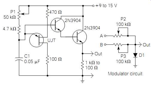
FIG. 9 Buffered UJT audio oscillator.
Using the values given in the illustration, a fairly wide range of the audio frequency spectrum can be produced by rotating P1 (frequency adjustment). The value of C1 can be increased for extremely low oscillations, and vice versa. The output of the Darlington pair can drive a small speaker directly, but the sound quality will be greatly improved by coupling the output with an audio transformer or, better yet, using a separate audio amplifier and speaker.
If you would like to experiment with some really unique sounds, build two of these UJT oscillator circuits and connect their outputs into the modulator circuit, also illustrated in Fig. 9. One UJT oscillator out put will connect to point A and the other, to point B. The output of the modulator circuit must be connected to the input of a separate amplifier and speaker. The diode can be any general-purpose rectifier diode.
An understanding of this modulator circuit requires an explanation of several new principles; the first involves diodes. When diodes are for ward-biased with very low voltages and currents, they react in a highly nonlinear fashion. This area of diode conduction is called the forward biased knee of the diode response.
A second new principle involves the process of modulation. Modulation occurs when two different frequencies are mixed in a nonlinear circuit.
The effect of modulation causes some additional frequencies to be created. For example, if a 1-kHz frequency and a 10-kHz frequency are applied to the inputs of a linear mixer, the output will be the original frequencies, only mixed together. If the same two frequencies are applied to the input of a nonlinear mixer circuit, the original frequencies will still appear at the output, but two additional frequencies, called beat frequencies, will also occur. The beat frequencies will be the sum and difference of the original frequencies. Using 1 kHz and 10 kHz as the originals, the beat frequencies will be 11 kHz (sum) and 9 kHz (difference).
When the two UJT oscillators are connected into the modulator circuit (with its output applied to the input of a power amplifier and speaker), P2 and P3 are adjusted to cause the outputs of the oscillators to fall into the "knee" area of D1's forward conduction response. You might have to add some additional series resistance between each oscillator and each modulator input. If this is the case, try increasing the resistance in 100-Kohm increments. When the two frequencies modulate, the sound produced will be instantly recognizable. This type of sound, or "tonality," has been in the background of most science fiction movies since the 1950s.
Forbidden Planet (movie) soundtrack
In 1956, MGM released a classic science fiction movie entitled Forbidden Planet, starring Walter Pidgeon, Anne Francis, and Leslie Nielsen. This movie was unique in that it contained no conventional music. Rather, the soundtrack was described as "tonalities," which were the original creation of Louis and Bebe Barron. I estimate that about 80% of these tonalities were generated with the fascinating circuit, called a ring modulator, illustrated in Fig. 10.
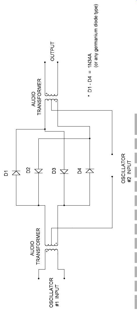
FIG. 10 A simple passive ring modulator circuit.
The simple modulator circuit shown in Fig. 9 can produce interesting modulation effects, but the original frequencies appear at the output along with the beat frequencies. The effect is somewhat muddy because of the various blends and amplitudes of the four frequencies (i.e., two beat frequencies plus two original frequencies). In contrast, the ring modulator circuit of Fig. 10 cancels out the two original frequencies, outputting only the beat frequencies. The effect is fascinating and quite impressive. The Fig. 10 circuit will function well with two audio signal sources of any type (i.e., two oscillator circuits of Fig. 9, two signal generators, two function generators, or any combination thereof). The modulator inputs must be several volts in amplitude for a suitable output.
Almost any two audio transformers will function well for the Fig. 10 ring modulator, but they must be matched (i.e., they must be the same model and type). Diodes D1 through D4 should be germanium types, although silicon diodes will work to some degree.
The theory of operation of the Fig. 10 circuit is fairly simple. Modulation occurs in the nonlinear diode circuitry, but the diodes are arranged so that the rectification process cancels out the original frequencies. Consequently, the only frequencies remaining at the output are the upper and lower modulation sidebands.
Ring modulators are used in many types of electronic music circuits, as well as sound-effect circuits, producing such effects as bells, clangs, and metallic sounds. They also produce a "harmonizing" effect if one of the oscillator inputs is held stable while a musical instrument input is applied to the other input.