AMAZON multi-meters discounts AMAZON oscilloscope discounts
Some circuits which do not fall into the earlier groups are included here. These are general but not related applications of transistors and diodes.
Ignition systems are an example; transistorized ignition systems for cars and trucks are surely just a matter of time. They offer longer life for the points in the internal-combustion engine; points have been and continue to be a weak link in today's high-performance automobiles. Transistor ignition will increase the reliability and efficiency of tomorrow's cars.
TRANSISTOR IGNITION SYSTEMS
From the first automobile ignition system designed, pitting and poor voltage output at high speeds have been a problem. The heavy current across the points causes wear and surface erosion, both of which mean the points require periodic replacement.
Also, the voltage output drops sharply at high speeds when the points are worn, causing incomplete combustion and consequent waste of fuel.
Although electronic ignition systems using tubes have been a possibility for a long time, only the transistor has made possible a rugged, efficient system with no filament warm-up necessary.
Three techniques are possible for using transistors and diodes in automotive ignition systems. (1) As shown in Part A of the diagram, primary-current switching can be used in a conventional system, where the transistor switch handles much larger currents than the breaker points. ( 2) Capacitor energy storage is another good ignition system. It comprises a transistor switch in series with the points, to discharge the capacitor in order to fire the spark plugs. ( 3) A transistor oscillator is used here to produce continuous or keyed pulses for the spark. All three circuits give a better performance than conventional systems.
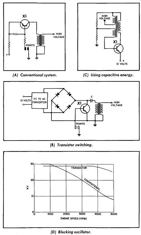
--------Transistor ignition systems. (A) Conventional system. (C) Using
capacitive energy. (B)Transistor switching. (D) Blocking oscillator.
An auto ignition system requires a properly timed spark of 15 to 35 kilovolts, with a peak spark power of about 900 watts. All three of these transistorized systems can meet these requirements, despite even a wide variation in battery voltage.
Transistor Switching
In the ordinary automotive ignition system the crankshaft, through gears, drives a cam which opens and closes the breaker points. When the points close, the primary current builds up to maximum. When the points open, the collapse of this magnetic field appears across the ignition-coil secondary as a high voltage.
A capacitor across the points reduces the arcing and provides a low-impedance path for the current How. But with the transistor in the circuit, the breaker points carry only 5% of the current, since the points are in the base circuit. The lower current flow across the breaker points will increase their life and reduce maintenance considerably.
After the breaker points open, a large reverse voltage appears across the primary coil and across the transistor. With a conventional 12-volt coil having a turns ratio of 1: 100, 300 volts could be developed across the transistor at maximum output. This is the same high voltage that causes arcing and pitting of contacts in conventional systems, and the transistor can be damaged unless some protection is provided. One method is to install a zener diode across the transistor terminals. A higher turns ratio (perhaps 1,000-to-l) can then be used for the transformer. Thus, the voltage across the transistor will be reduced while still providing the required high-voltage output.
One marked advantage of transistor ignition systems can be seen from the graph in Part B. The available output-voltage versus-engine-speed curve is quite flat for a transistor system. By contrast, in the conventional system the output voltage drops off at higher speeds, since the current build-up is slower. Hence, when the points close, the current How is not maximum. The result is poorer circuit efficiency.
Capacitive Energy
Although the usual ignition system uses inductive energy, it is possible to design systems in which the energy is stored in a capacitor. This type of system, although complex, is very effective.
As shown in Part C, the 12-volt supply is amplified by a DC-to AC converter. A bridge circuit of four diodes produces a DC out put of about 300 volts used for charging the capacitor. When the transistor base circuit is completed through the points, the transistor acts as a switch so that the storage capacitor will discharge through the coil and produce the required high voltage. Protection for this transistor from high-voltage transients (and the bridge high voltage) can be provided by zener diodes or several transistors in series ( or both). In this type of circuit there are two choices-either the points can do the triggering, or a rotating magnet can be used to induce pulses in a coil and these pulses then amplified for switching purposes.
Transistor Oscillators
In the third system, a blocking oscillator can be used as shown in Part D. Here there are two possibilities-a continuous output can be obtained and used for spark, or the circuit can be made to oscillate only as required. With ferrite cores used in the trans former, frequencies beyond 20 khz are possible. Much lower frequencies can be obtained by using other core materials. This transistor also requires protection from high voltages.
METER PROTECTION CIRCUIT
When a DC milliammeter or an ammeter is connected into a circuit to measure an unknown current, the meter movement must be protected from damage. A 2N256 power transistor is ideal for this purpose, as shown in the circuit.
R2 is the unknown impedance through which the current is to be measured and across which the voltage is to be held to 22.5 volts. The current is indicated by meter M. The emitter is sup plied from the 6-volt battery and adjusted by resistor R1 to the highest current the meter can withstand ( in this case, 25 milli amperes). Meters for higher currents may be used, up to the 3 ampere maximum rating of the transistor, provided the power dissipation rating of the transistor is not exceeded.
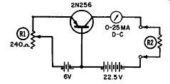
-------------- Meter protection circuit.
TUNNEL-DIODE FM TRANSMITTER
Its negative-resistance characteristic makes the tunnel diode ideal for use as an oscillator in the FM transmitter. Part A of the diagram shows a basic tunnel-diode oscillator. Its frequency is determined primarily by the LC components in the cathode circuit. Voltage divider R1-R2 provides a stable low-impedance voltage of about 150 mv for the anode, and capacitor C1 is used as the anode RF bypass.
Part B shows a transistor emitter-follower stage used to amplify the audio input from the microphone. Amplified audio is fed, through capacitor C2, to the tunnel-diode anode. Modulated FM is obtained in the antenna circuit as the audio signal instantaneously alternates the anode bias. For a tunnel diode, the characteristic curve is not perfectly linear in the negative-resistance region.
This causes the negative conductance to change slightly with the bias. FM deviations of +75 khz are possible from this circuit.
This FM transmitter can be used as a wireless portable micro phone. With an average FM receiver having a sensitivity of 10 µ.v, an operating range in excess of 100 feet can be obtained.
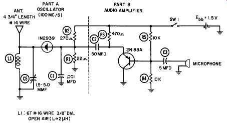
----------------- Tunnel-diode transmitter.
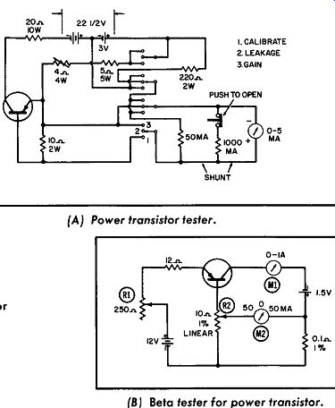
---------------------- Transistor testers. (A) Power transistor tester.
(B) Beta tester for power transistor.
TRANSISTOR TESTERS
This diagram shows two circuits used for transistor testing.
Part A depicts a circuit for testing power transistors. It will reveal all combinations of opens, shorts, leakage, and voltage breakdown, plus power gain as simulated by a DC test.
There are three switch positions: Leakage, Power Gain, and Calibrate. A spring return normally keeps the switch in the Leakage position. In the Calibrate position, the Calibrate knob is adjusted until the meter reads 2 ( 400 ma). If this is impossible, replace the battery. ( Do not push the button.) In the Leakage position, a reading greater than 0.1 ( 20 ma) indicates a C-B, C-E, or C-B-E short. If the reading is less than 0.1, push the button. A new reading greater than 2 ( 2 ma) means excessive leakage.
Creeping upscale is definitely leakage.
In the Gain position, a reading greater than 0.5 ( 100 ma) is a B-E short or any open. If the reading is below 0.5 ( 10 ma), there is a C-B, C-E, or C-B-E short. A reading of 2.2 (44 ma) indicates an available power gain of 30 db. Higher readings indicate lower power gains.
Part B shows a beta tester for power transistors. A PNP power transistor such as the 2N255 or 2N256 is plugged into the test socket. R1 is adjusted for the desired collector current ( such as 0.5 ampere) as read on meter M1. Then R2 is adjusted for zero current on meter M2. R2 has a dial scale of 0-100 divisions on which beta is read directly.
NPN power transistor may be tested by reversing the battery polarities and the connections to meter M1.
DIODE PROTECTIVE CIRCUITS
A low feedback bias can be obtained in vacuum-tube circuitry by using a silicon-junction diode such as the 1N465-IN470 in series with the cathode to provide a self-bias cathode voltage. The loss in small-signal gain of the vacuum-tube stage will be slight when a diode is used for cathode bias, because the circuit dynamic impedance is now much less than the static resistance. In amplifiers ( which must have a flat response down to very low frequencies), the use of silicon junction diodes as bias elements will eliminate the need for large bypass capacitors.
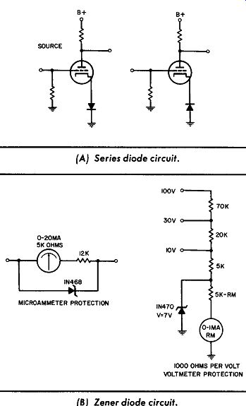
-------------------- Diode protective circuits.
(A) Series diode circuit.
(B)Zener diode circuit.
One or more diodes may be used in series in the forward direction, as shown in Part A of the diagram. However, at higher bias levels it may be more desirable to use a single diode in the zener region, as shown in Part B. Meter protection is another use for the diode. Both the forward and the reverse characteristics of low-voltage silicon junction diodes can be used to protect electrical instruments from accidental overloads. In order to protect micro-ammeters, it is usually necessary to add external series resistance until the voltage drop across the meter and resistor is approximately 0.4 volt when full-scale current is flowing. At 25°C., a silicon junction diode like the IN468 will pass only one microampere or so at a forward voltage of 0.4 volt. This means that if the diode is connected in parallel with the meter plus an external resistor, negligible meter error will result at full scale or less. Yet the meter movement will be overloaded by only a factor of two or three, even by current overloads as high as 200 to 300 milliamperes.
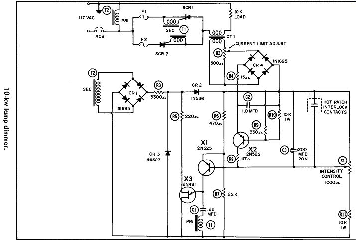
Voltmeters with a range of 0.5 to 1.0 volt can be protected by using the forward characteristic of a diode. For higher-voltage instruments, however, very sharp protection can be realized by using a sharp breaking zener characteristic, such as can be found in a IN470 and IN200. LAMP DIMMER This circuit uses a pair of C-60B silicon-controlled rectifiers ( SCR's) to control a 10-kw load of incandescent lighting. Protection against large surge currents is required because of the low resistance and high current of the lamp load. Here, X1 is used to control unijunction X3.
The two back-to-back SCR's control the current through the load, and the rest of the circuit is used to control the SCR's them selves. Intensity control R1 determines the base drive for transistor X1. In the current-limiting circuit, X2 provides overriding control and is driven, through CTI, by the current in the load.
R2 sets a limit beyond which X2 will conduct and reduce the base potential of X1. This bias reduces the collector current of X1 and ( through the SCR) the voltage applied to the load. The time constants of the control circuit give a response of one half cycle of line frequency.
---------------
Assume the circuit is energized with full output ( R1 setting minimum). Delay capacitor C3 will cause the firing angle of both SCR's to advance from maximum phase retard to full output. This will occur over several cycles of line frequency. When the load exceeds the peak-current limit of one cycle during this starting sequence, transistor X2 will take over and keep the SCR firing angle retarded until the load resistance approaches its steady state value.
Control R2 is set for the maximum allowable peak current rating of the SCR' s. This permits the SCR's to be safely used at their maximum rated junction temperature in order to bring the load quickly to full output.
A mechanical patch interlock is provided in case an additional load is plugged in while the circuit is energized. When momentarily closed, this interlock discharges C3 and reinitiates the starting sequence. With the interlock mounted as an integral part of the plugging arrangement, the delay circuit will be reset every time a load is added. This will allow maximum long-term reliability by holding recurring peak currents through the SCR' s to the rated values.