AMAZON multi-meters discounts AMAZON oscilloscope discounts
The basic method of obtaining a high-voltage supply is to step up an ac mains supply via a transformer.
At the same time, the transformer can be tapped, or provided with separate windings, to produce any other lower or inter mediate voltages which may be required.
Voltage step-up or step-down, using a transformer, is possible only with an alternating-current input. The resulting output is also ac, from which it follows that further components will be required in a power supply to provide stepped-up or-down direct-current voltages, such as required for the anode of a tube. Basically, this involves rectification of the transformed voltage, with the addition of smoothing, if necessary, to remove any remaining "ripple," in the dc output.
Voltage regulation may also be necessary, even if only aimed at limiting the value of transient voltages which may be introduced in the power-supply circuit. In that case, we are concerned with the peak inverse voltages (piv) which may be introduced in the power -supply circuit, affecting the loading of the components.
Voltage regulation itself can be expressed as a percentage: regulation (%) - 100(E1 -E2) E2 where E1 is the no-load voltage (no current flowing in the load circuit), and E2 is the full load voltage (rated current flowing in load circuit).
Three basic rectifier circuits are shown in Fig. 27-1. A single diode will provide half -wave rectification.
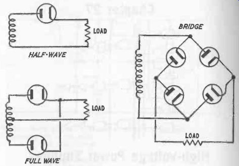
Fig. 27-1. Three basic rectifier circuits.
Two diodes can provide full-wave rectification, with the circuit completed through the transformer center tap. Alternatively, the bridge type circuit may be used for full-wave rectification.
Either tubes (diodes) or metal rectifiers can be used in such circuits.
Metal rectifiers have the advantage that they require no heater supply, but have to be fitted with cooling fins to dissipate the heat generated by their relatively high forward resistance. Tubes also get hot, and both need plenty of space within the cabinet, and good ventilation. Power supplies of these types, therefore, tend to be heavy and bulky.
Silicon power diodes are generally preferred to tubes or metal rectifiers. They can be produced in virtually miniature size, require no heater current, and have relatively low heating (and thus much higher efficiency), because of their very low forward resistance. While this latter feature is highly desirable, it does also emphasize the potential weakness of the silicon diode to the effect of high voltage surges developing which will destroy the diode. This is because of the relatively low piv values such diodes can withstand. Unfortunately, too, it is also a characteristic of silicon diodes that they tend to fail in a shorted condition, rather than "open," so that failure of one diode in a series could readily cause the remainder to fail as well.
Series connection of silicon diodes is generally necessary to realize the piv rating required. This is decided basically by the piv likely to be developed by the rectifier circuit. In the case of a single diode circuit, the piv across the diode will be approximately 1.4 times the ac voltage across the transformer coil. The center-tap circuit will yield a piv of about 2.8 times the ac voltage across each half of the transformer coil. The bridge circuit will again yield about 1.4 times the voltage across the coil.
The required rating can be built up by connecting as many diodes in series as necessary to factor their individual rating by 2, 3, 4 times, etc., allowing a suitable margin of safety.
This, however, will only be valid if the diodes are exactly matched in characteristics (particularly their reverse resistance). This is unlikely in practice, and so equalizing resistors are normally connected across each diode-Fig. 27-2. Alternatively, equalizing capacitors may be used in some circuits. Both configurations, incidentally, also act as transient suppressors to protect the diodes against surges of high current. Since capacitors are more effective in this respect, resistors and capacitors may be used in series across each diode as equalizing/ damping devices. Further protection may also be incorporated in the rectifier circuit by including a fuse to open-circuit a chain of diodes in the event of overload, or failure of one of the diodes.
One other precaution which may be necessary with silicon diodes is to "balance" their rating against temperature.
Although they do not generate much heat themselves, their performance is temperature dependent, and the maximum rating applies with a temperature limit. If they are to be worked at a higher ambient temperature, derating of performance is necessary. Temperatures for a maximum current rating may range from as low as 25°C to as high as 70°C, depending on type and manufacture. Derating, typically, is of the order of 10 percent per 10°C temperature rise above the rated temperature.
FILTERS
The output from a rectifier circuit is pulsating dc. To render this in the form of smooth dc, filtering must be applied.
While this may not be strictly necessary for tube operation, it is absolutely necessary to eliminate (or at least reduce) the "hum" content of the power supply applied to various stages of a transmitter or receiver circuit.
Effective smoothing of the supply is readily achieved by means of a capacitor -input filter, which may be either single -section or two section-Fig. 27-3. The single-section filter is generally adequate for radio transmitters, but the two -section circuit is preferable for radio receivers.
The addition of a "bleeder" resistor is generally recommended, its purpose being to discharge the capacitors when the power supply is not in use.
The value of the bleeder resistance should be chosen so that it draws 10 percent or less of the rated output current of the supply. (It can be calculated directly as 1000 E/I ohms, where E is the output voltage, and I is the load current in milliamps.)
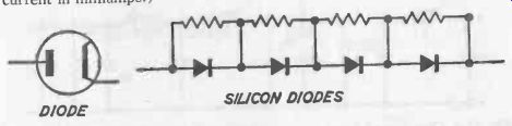
Fig. 27-2. Diodes with equalizing resistors.
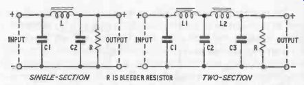
Fig. 27-3. Single- and two-section smoothing filters.
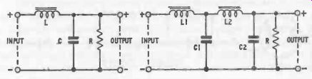
Fig. 27-4. Choke-input filters.
The ripple voltage remaining will be governed by the values of the capacitors and inductance. Typical values are 8µF for the capacitors (although C1 can be reduced to 4µF in the two -section circuit), with an inductance of 20 to 30 henries. Ripple voltage will get smaller as capacitance and inductance are made larger. Few problems are imposed in matching component values, and satisfactory smoothing is readily obtained. Capacitor -input filter circuits, however, exhibit poor voltage-regulation properties when used with varying loads.
The choke-input filter provides better voltage regulation, but less effective smoothing. Again, it can be single -section or two-section--Fig. 27-4. The two -section circuit is generally superior as regards smoothing.
Note again the use of a bleeder resistor to discharge the capacitor(s) when the power supply is not in use.
The first inductance can, with advantage, be of the "swinging choke" type-that is, having swinging characteristics over a range of about 5 to 20 henries over the full output current range. The highest value will then apply when there is no output load on the power supply other than the bleeder resistor. The second choke should then have a constant inductance of 10 to 20 henries with varying dc load currents.
With this type of circuit, it is possible to use capacitors with lower rated voltage than those necessary for a capacitor-input filter (which have to have a rating higher than the peak transformer voltage). However, a similar high-voltage rating is usually advised, as in the event of failure of the bleeder resistor the voltages would rise to these peak figures.
OUTPUT VOLTAGE
Basically, the dc output voltage is about 0.9 times the ac voltage across the transformer secondary in the case of a single diode or bridge circuit; and about 0.45 times the ac voltage across the transformer secondary in the case of the bridge circuit.
With capacitor-input filters, the secondary rms voltage required is thus 1/0.9 or 1.1 times the required dc output voltage, to allow for voltage drops in the rectifier and filter circuits, and in the transformer itself. In the case of a center-tapped circuit, this voltage must be developed across each side of the secondary center tap.
With a choke-input filter circuit following the rectifier, the required transformer secondary voltage can be calculated directly from:
where E = 1.1 (E + 1(R1 + R2) + E)
° 1000 E = full load rms secondary voltage
E = required dc output voltage (The open circuit voltage will usually be anything from 5 to 10 percent higher.)
Er = voltage drop in the rectifier
R1, R2 = resistance in filter chokes
VOLTAGE STABILIZATION
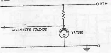
Fig. 27-5. Voltage stabilization with VR tube.
A basic method of obtaining voltage stabilization is by the use of a voltage-regulating tube in series with a limiting resistor, as shown in Fig. 27-5. The initial (unregulated) voltage needs to be higher than the starting voltage of the tube, which is usually about 30 percent higher than the operating voltage. The value of the limiting resistor is chosen to just pass the maximum tube current when there is no load current. With load added, the tube can then work down to its minimum current condition. Within this range the voltage drop of the tube is constant, thus providing a point for tapping off a stabilized voltage. Voltage regulation better than 10 percent can readily be achieved; and with the tubes in series, stabilization is further improved down to about 1 percent.
The use of two tubes in series also enables two different values of regulated voltage to be tapped, one from each tube.
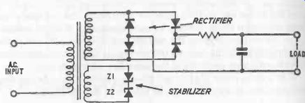
Fig. 27-6. Stabilization by zener diodes.
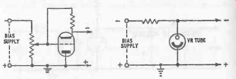
Fig. 27-7. Stabilization by bias voltage.
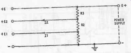
Fig. 27-8. Conventional voltage divider.
Figure 27-6 shows how Zener diodes can also be used to stabilize a high-voltage supply obtained from a transformer. The low -voltage Zener diodes (Z1 and Z2) are simply connected in back-to-back configuration across a low-voltage winding on the transformer.
BIAS VOLTAGES
Bias-supply requirements are basically a fixed voltage of the required value to set the operating point of a tube. The output should be well filtered, and capacitor -input filters are commonly preferred. A bleeder resistor is effective as a voltage regulator since it provides a dc path from the grid to the cathode of the tube being biased. However, to be really effective, this will need a low resistance value so that the current flowing through the bleeder resistor is several times the maximum grid current to be expected, which is wasteful of power.
In particular cases, therefore, it may be expedient to adopt more efficient methods of bias -voltage stabilization. Two such stabilizing circuits are shown in Fig. 27-7. One uses a triode as a regulator, and the other a VR tube. The latter is only applicable where the voltage and current ratings of the tubes permit their application.
VOLTAGE DIVIDERS
The conventional type of voltage divider is based on the circuit shown in Fig. 27-8. Basically, it comprises a series of resistors (or a resistor with a series of tapping points), from which voltages lower than the input voltage can be drawn by connecting to an appropriate tap.
The end resistor is considered only as a "bleeder," carrying a bleeder current which is normally 10 percent or less of the total load current.
The values of resistors required then follow from:
R1 = E1 lb E2 – E1 lb + I1 E - E2 R2 = R3 =
Ib ± + I2
Voltage regulation is very poor with voltage dividers of this type because the voltage taken from any tap depends on the current drawn from the tap (and will thus vary with varying load). Thus, while they are suitable for constant -load applications, additional voltage regulation would have to be applied for stabilization with varying loads.
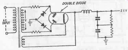
Fig. 27-9. Voltage -multiplier circuit.
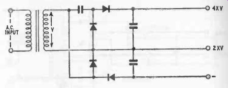
Fig. 27-10. Voltage -multiplier circuit using diodes.
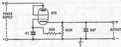
Fig. 27-11. Variable voltage supply.
VOLTAGE MULTIPLIERS
Rectifiers can also be used as voltage-multipliers, in integer factors--a feature which can often be used to advantage.
It is possible, for example, to accept an ac input direct into a rectifier circuit, without having to employ a transformer, and obtain both rectification and voltage doubling. Such a circuit is shown in Fig. 27-9. Each capacitor is charged separately to the same dc voltage from the two diodes and then discharged in series into the same load circuit (thus doubling dc output voltage obtained).
Figure 27-10 shows an extension of this principle, utilizing four di odes. The output from this circuit provides both voltage doubling and voltage quadrupling.
As with voltage dividers, voltage multipliers tend to offer poor voltage regulation, although this is less marked with silicon diodes as compared with diode tubes and metal rectifiers.
VARIABLE-VOLTAGE SUPPLIES
A simple type of variable-voltage supply for use with a constant-voltage power supply is shown in Fig. 27-11. This circuit eliminates series resistors as a source of voltage drop and, as a consequence, maintains a substantially constant source impedance. Voltage regulation is also provided, as well as voltage variation via the variable resistor, although the degree of stabilization will deteriorate with increasing voltage output. It is, however, another example of how simple circuits can often be used to provide solutions to particular requirements in transmitter and/or receiver circuits.
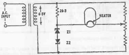
Fig. 27-12. Stabilized heater supply.
STABILIZED TUBE HEATER SUPPLIES
The heater supply for tubes tends to be regarded as non-critical, and conveniently supplied direct from a separate low -voltage coil on the power transformer, without rectification. As a minimum precaution, it is generally desirable to use separate heater supplies (e.g., separate transformer coils) for oscillator tubes, and voltage stabilization may well be considered as a method of further improving the overall stability of the stage(s) involved.
A simple circuit which offers considerable possibilities in this respect is shown in Fig. 27-12, employing two Zener diodes in back-to-back bridge circuit configuration. The variable resistor acts as a trimmer to set up the circuit, its value being about 20 percent of the total resistance value of the lower arm of the bridge. Voltage stabilization of better than 1 percent is claimed for this circuit, with a transformer voltage change of up to 13 percent.
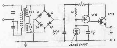
Fig. 27-13. Transistor power supply.
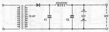
Fig. 27-14. Simple regulation circuit.
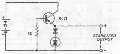
Fig. 27-15. Simple low-loss stabilizing circuit.
TRANSISTOR POWER SUPPLIES
Transistor circuits require only low voltages and thus considerably simplify power supply requirements, particularly as only a single voltage is usually required. They may, however, be fed from an ac supply, in which case, similar requirements apply as regards rectification and smoothing following the transformer. For voltage stabilization, a Zener diode is normally employed (the Zener diode is virtually the counterpart of the VR tube in higher voltage circuits).
A typical modern transistor power supply circuit is shown in Fig. 27-13, which is also notable for incorporating electronic smoothing. There are numerous variations on a similar theme but, in general, shunt regulation is taking preference over series regulation, as this will permit the output to be short-circuited without damage.
A very much simpler system is shown in Fig. 27-14, which merely uses half-wave rectification followed by smoothing, and a battery of the same voltage as the dc output "floating" across the output. This battery provides extremely good stabilization and at the same time can also act as a ripple filter. Capacitor C2, in fact, is not really necessary. Basically, the battery provides an additional source of power to combat voltage drop under load. A similar system of "floating" a battery across the output can equally well be applied to a full -wave rectifier output. Zener diode stabilization can also be added, if necessary, for an even higher degree of stabilization.
Stabilization is less readily provided across a direct battery feed to a transistor circuit since conventional methods of stabilization using Zener diodes and resistors almost inevitably mean a large increase in current drain, further loading the batteries. Various ingenious solutions have been proposed to combat this, such as the use of current -limiting circuits (which also safeguard transistors against overload). Figure 27-15 shows a simple low-loss stabilizing circuit, based around the use of a transistor as a constant current device, which can readily be extended to two stages if necessary.