AMAZON multi-meters discounts AMAZON oscilloscope discounts
Data Acquisition boards and external units allow one to measure signals and transfer the data into a computer. A standard commercial DAQ card contains an ADC (analog-to-digital converter) and a DAC (digital-to-analog converter) which allows input and output of analog and digital signals in addition to digital input/output channels.
To understand DAQ boards better, here are some digital fundamentals you may want to familiarize yourself with:
Sampling -- The data is acquired by an ADC using a process called sampling. Sampling an analog signal involves taking a sample of the signal at discrete times. This rate at which the signal is sampled is known as sampling frequency. The process of sampling generates values of a signal at time interval as shown in this figure:

The sampling frequency defines the quality of the analog signal that is converted. Higher sampling frequencies allow better-quality conversions of analog signals. The minimum sampling frequency required to represent the signal should be at least twice the maximum frequency of the analog signal under test. This is called the Nyquist frequency. In the figure above, an example of under-sampling is shown. If the sampling frequency is equal to or less then twice the frequency of the input signal, a signal of lower frequency is generated -- this phenomenon is known as aliasing.
Analog to Digital Conversion (ADC) -- Once the signal has been sampled, it needs to be converted into digital code. This process is called analog to digital conversion and is illustrated below for a hypothetical 3-bit ADC:

Common DAQ boards have different sampling frequencies. e.g., this PCI board from IOTech is a 16-bit model with a 1-MHz sampling rate.
Most boards also have a multiplexer that acts like a switch between different channels and the ADC. Hence, with one ADC, it's possible to create a multichannel-input DAQ board. The IOTech board has 24 channels. This makes it possible to acquire up to 24 analog signals in parallel. Note: the sampling frequency will be divided by the number of parallel channels.
Bit Resolution -- Accuracy and precision of the input (analog) signal converted into the digital domain depends on the number of bits the ADC uses. The resolution of the converted signal is a function of the number of bits the ADC uses to represents the digital data. The higher the resolution, the higher the number of divisions the voltage range is broken into, and hence, the smaller the detectable voltage change. An 8-bit ADC has 256 levels (28) compared to a 12-bit ADC that has 4096 levels (212). Therefore, a 12-bit ADC will be able to detect smaller increments of the input signals than a 8-bit ADC. LSB, or least significant bit, is the minimum increment of the voltage that a ADC can convert. Therefore, LSB varies with the operating input voltage range of the ADC. The figure below illustrates the resolution for a (very hypothetical!) 3-bit ADC. FS is full scale. If the full scale of the input signal is 5V then the LSB for a 3-bit ADC corresponds to 5/(23) = 0.625V. This is very poor! On the other hand, in a 12-bit ADC the least significant bit will be 5/(212) = 5/4096 = 0.00122V. If detecting smaller changes is important, higher-resolution ADCs must be used.

Resolution is very important in data acquisition systems. Let's go through another example. Suppose we were measuring the height of water in a 40-foot tall storage tank using an instrument with a 10-bit ADC. 0 feet of water in the tank corresponds to 0% of measurement, while 40 feet of water in the tank corresponds to 100% of measurement. Because the ADC is fixed at 10 bits of binary data output, it will interpret any given tank level as one out of 210 (or 1024) possible states. To determine how much physical water level will be represented in each step of the ADC, we need to divide the 40 feet of measurement span by the number of steps in the 0-to-1024 range of possibilities, which is 1023 (one less than 1024). Doing this, we obtain a figure of 0.039101 feet per step. This equates to 0.46921 inches per step, a little less than half an inch of water level represented for every binary count of the ADC.

The step value of 0.039101 feet (0.46921 inches) represents the smallest amount of tank level change detectable by the instrument. Yes, this is a small amount -- less than 0.1% of the overall measurement span of 40 feet. However, for some applications it may not be fine enough. Suppose we needed this instrument to be able to indicate tank level changes down to one-tenth of an inch. In order to achieve this degree of resolution and still maintain a measurement span of 40 feet, we would need an instrument with more than 10 ADC bits.
To determine how many ADC bits are necessary, we need to first determine how many 1/10 inch steps there are in 40 feet. The answer to this is (40 x 12) / 0.1, or 4800 1/10 inch steps in 40 feet. Thus, we need enough bits to provide at least 4800 discrete steps in a binary counting sequence. 10 bits gave us 1023 steps, and we knew this by calculating 2 to the power of 10 (210 = 1024) and then subtracting one. Following the same mathematical procedure, 211-1 = 2047, 212-1 = 4095, and 213-1 = 8191. 12 bits falls shy of the amount needed for 4800 steps, while 13 bits is more than enough. Therefore, we need an instrument with at least 13 bits of resolution.
Linearity
In a perfect world ... if a voltage applied to the input of an analog-to-digital converter (ADC) is increased linearly, the resulting digital codes will also increment linearly. Graphically, here's how linearity may be visualized:
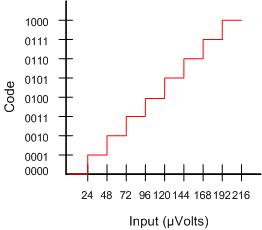
above: Transfer characteristic of a
paradigm analog-to-digital conversion.
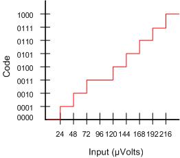
Most commercially-available DAQ boards have some inherent non-linearity. This specification is noted in the brand/model specifications as differential non-linearity.
Notes:
- DNL (Differential Non-Linearity) shows how much two adjacent code analog values deviate from the ideal 1-LSB step.
- INL (Integrated Non-Linearity) shows how much the DAC transfer characteristic deviates from an ideal one. I.e., the ideal characteristic is usually a straight line; INL shows how much the actual voltage at a given code value differs from that line, in LSBs (1-LSB steps).
Settling Time
On most DAQ boards, an incoming analog signal is first selected by a multiplexer, then amplified before it's converted to the digital domain by the ADC. The amplifier used between multiplexer and ADC must be able to track the output of the multiplexer; otherwise, the ADC will convert the signal that is still in transition from the previous channel's value to the current channel value. Suboptimalsettling time can be a major problem because it changes with sampling rate and the amplification gain of the DAQ board. Look for settling time specs to be around 5µs to 1 LSB for full-scale step.
Digital-to-Analog Converter and DAQ-board Components
This figure below is a block diagram of a typical 16-bit 200-kHz DAQ board. It plugs into an open PCI slot in you PC.

Other Factors That Affect the Quality and /or Accuracy of Data
Data Jitter
What is Jitter?
Various factors
(e.g. crystal oscillators, component tolerances, ADCs and DACs frequency
mismatch, electromagnetic fields, etc.) can prevent
these signals from reaching DAQ board (or its specific internal components)
at exactly the intended time. This timing inaccuracy
is what is
known
as "jitter".
Jitter: A Graphical Explanation

The top waveform is perceived as a perfect digital signal, the wave definition and timing are theoretically flawless. The lower waveform represents the exact information, but with jitter. In contrast, the waveform is distorted and the timing is inaccurate.
Also see: Digital-to-Analog Converter, Analog-to-Digital Converter, Digital FilterOther Resources on this Topic:
Anti-aliasing (Stanford University) -- covers problems with the Anti-aliasing Filter.