AMAZON multi-meters discounts AMAZON oscilloscope discounts
Objectives
This section will help to refresh and expand your understanding of basic electrical components and the basic terms used in electricity as required for instrumentation.
This section discusses
_ Basic passive components (resistors, capacitors, and inductors) used in electrical circuits
_ Applications of Ohm's law and Kirchoff's laws
_ Use of resistors as voltage dividers
_ Effective equivalent circuits for basic devices connected in series and parallel
_ The Wheatstone bridge
_ Loading of instruments on sensing circuits
_ Impedances of capacitors and inductors
It is assumed that the student has a basic knowledge of electricity and electronics and is familiar with basic definitions. To recap, the three basic passive components-resistors, capacitors, and inductors-as well as some basic formulas as applied to direct and alternating currents will be discussed in this section.
1. Introduction
Electrical power can be in the form of either direct current (dc) (one direction only) or alternating current (ac) (the current reverses periodically, see FIG. 1). In ac circuits the electromotive force drives the current in one direction then reverses itself and drives the current in the reverse direction. The rate of direction change is expressed as a frequency f and is measured in hertz (Hz), i.e., cycles per second.
Electrical signals travel at the speed of light. The distance traversed in one cycle is called a wavelength l, the relationship between frequency and wavelength (meters) is given by the following equation:
(eqn. 1)
where c is the speed of light (3 × 10^8 m/s).
In both dc and ac circuits, conventional current was originally considered to flow from the more positive to the less positive or negative terminal. It was later discovered that current flow is really a flow of electrons (negative particles) that flow from negative to positive. To avoid confusion, only conventional current flow will be considered in this text, i.e., current flows from positive to negative.
When measuring ac voltages and currents with a meter, the root mean square (rms) value is displayed. The rms value of a sine wave has the same effective energy as the dc value. When displaying sine waves on an oscilloscope it is often more convenient to measure the peak-to-peak (pp) values as shown in FIG. 1.
The peak amplitude of the sine wave (Vp or Ip) (0 to peak) is then (p - p)/2, and the rms value is given by
(eqn. 2)
The basic sine wave shown in FIG. 1 can be equated to a 360° circle or a circle with 2p rad. The period (cycle time) of a sine wave is broken down into four phases each being 90° or p/2 rad. This is derived from the trigonometry functions, and will not be elaborated upon.
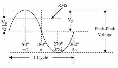
FIG. 1 The basic sine wave.
2. Resistance
It is assumed that the student is familiar with the terms insulators, conductors, semiconductors, electrical resistance, capacitance, and inductance. Hence, the basic equations commonly used in electricity will be considered as a starting point.
2.1 Resistor formulas
The resistivity r of a material is the resistance to current flow between the opposite faces of a unit cube of the material (ohm per unit length). The resistance R of a component is expressed by
(eqn. 3)
where l is the length of the material (distance between contacts), and A is the cross-sectional area of the resistor; l and A must be in compatible units.
TABLE 1 gives the resistivity of some common materials. The resistivity r is temperature dependant, usually having a positive temperature coefficient (resistance increases as temperature increases), except for some metal oxides and semiconductors which have a negative temperature coefficient. The metal oxides are used for thermistors. The variation of resistance with temperature is given by
RT2 = RT1(1 + a T) (eqn. 4)
where RT2 = resistance at temperature T2
RT1 = resistance at temperature T1
a = temperature coefficient of resistance
T = temperature difference between T1 and T2
The variation of resistance with temperature in some materials (platinum) is linear over a wide temperature range. Hence, platinum resistors are often used as temperature sensors.
Ohm's law applies to both dc and ac circuits, and states that in an electrical circuit the electromotive force (emf) will cause a current I to flow in a resistance R, such that the emf is equal to the current times the resistance, i.e.
E = IR (eqn. 5)
This can also be written as
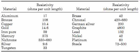
TABLE 1 Resistivity of Some Common Materials
where E = electromotive force in volts (V)
I = current in amperes (A)
R = resistance in ohms (?)
Example 1 The emf across a 4.7-k-ohm resistor is 9 V. How much current is flowing? Power dissipation P occurs in a circuit, whenever current flows through a resistance. The power produced in a dc or ac circuit is given by
P = EI (eqn. 6)
where P is power in watts. (In ac circuits E and I are rms values).
Substituting Eq. (eqn. 1) in Eq. (eqn. 6) we get
(eqn. 7)
In an ac circuit the power dissipation can also be given by P = Ep Ip/2 (eqn. 8)
where Ep and Ip are the peak voltage and current values.
Example 2 What is the dissipation in the resistor in Example 1?
P = EI = (9 × 1.9) mW = 17.1 mW
Carbon composition resistors are available in values from 1 ohm to many mega-ohms in steps of 1, 2, 5, and 10 percent, where the steps are also the tolerances, as well as being available in different wattage ratings from 1/8 to 2W.
The wattage rating can be extended by using metal film or wire-wound resistors to several tens of watts. When choosing resistors for an application, not only should the resistor value be specified but the tolerance and wattage should also be specified. The value of carbon resistors is indicated by color bands and can be found in resistor color code charts.
Power transmission is more efficient over high-voltage lines at low current than at lower voltages and higher currents.
Example 3 Compare the energy loss of transmitting 5000 W of electrical power over power lines with an electrical resistance of 10 ohm using a supply voltage of 5000 V and the loss of transmitting the same power using a supply voltage of 1000 V through the same power lines.
The loss using 5000 V can be calculated as follows:
If, however, the supply voltage was 1000 V the loss would be So that in going from 5000 to 1000 V, the losses increase from 10 to 250 W
2.2 Resistor combinations
Resistors can be connected in series, parallel, or a combination of both in a resistor network.
Resistors in series are connected as shown in FIG. 2a, their effective total value RT is the sum of the individual resistors, and is given by (eqn. 9)
Example 4 What is the current flowing in the resistor network shown in FIG. 2a?
Voltage dividers are constructed using resistors connected in series as in FIG. 2a. A divider is used to reduce the supply voltage to a lower voltage value. The output voltage from the resistive divider can be calculated by multiplying the value of the current flowing by the value of the resistor across which the voltage is being measured, or by using the resistor ratios.
Example 5 What is the value of Vout across R3 with respect to the negative battery terminal in FIG. 2a?
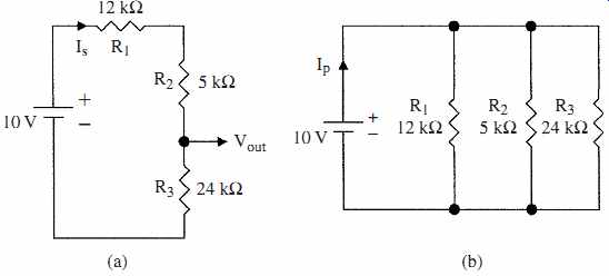
FIG. 2 Resistors connected in (a) series and (b) parallel.
Since the current flowing is the same in all resistors Vout = 0.244 × 24 kOhm= 5.8 V
Thus, using the resistance values in the example 5.86 V is obtained from a 10-V supply. Alternatively, Vout can be calculated as follows
From which we get
(eqn. 10)
This shows that the value of Vout is the supply voltage times the resistor ratios. Using this equation in Example 5
Potentiometers are variable resistance devices that can be used to set volt ages. They can have linear or logarithmic characteristics and can be constructed using carbon film tracks, or wire wound if longevity and accuracy is required (see FIG. 3b and c). A wiper or slider can traverse the track to give a variable voltage. A potentiometer is connected between a supply voltage and ground as shown in FIG. 3a. Using a linear potentiometer the wiper can be used to obtain a voltage proportional to its position on the track making a voltage divider. In FIG. 3b the output voltage is proportional to shaft rotation, and in FIG. 3c the output voltage is proportional to linear displacement. Linear potentiometers are used to convert mechanical movement into electrical voltages.
Logarithmic devices are used in volume controls (the ear, for instance, has a logarithmic response) or similar applications, where a logarithmic output is required.
FIG. 3 Circuit of (a) voltage divider potentiometer, (b) rotational carbon potentiometer, and (c) wire-wound slider type potentiometer.
Resistors in parallel are connected as shown in FIG. 2b, and their total effective value RT is given by (eqn. 11)
Example 6 What is the current Ip flowing in the circuit shown in FIG. 2b, and what is the equivalent value RT of the three parallel resistors?
RT = 120 kOhm/39 = 3.08 kOhm
Ip = 10/3.08 kOhm= 3.25 mA
Kirchoff's laws apply to both dc and ac circuits. The fist law (voltage law) states that in any closed path in a circuit, the algebraic sum of the voltages is zero, or the sum of the voltage drops across each component in a series circuit is equal to the source voltage. From FIG. 4a we get
(eqn. 12)
Kirchoff's second law (current law) states that the sum of the currents at any node or junction is zero, i.e., the current flowing into a node is equal to the cur rent flowing out of the node. In FIG. 4b for the upper node we get
(eqn. 13)
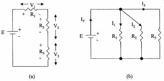
FIG. 4 Resistor networks to demonstrate Kirchoff's (a) voltage law
and (b) current law.
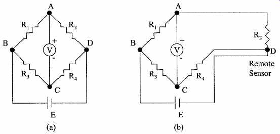
FIG. 5 Circuit of (a) Wheatstone bridge and (b) compensation for lead
resistance used in remote sensing.
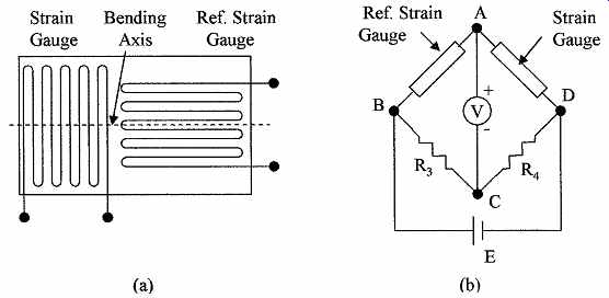
FIG. 6 Showing (a) strain gauge with reference gauge and (b) strain
gauges used in a Wheatstone bridge.
The Wheatstone bridge is the most common resistance network developed to measure small changes in resistance and is often used in instrumentation with resistive types of sensors. The bridge circuit is shown in FIG. 5a. Four resistors are connected in the form of a diamond with the supply and measuring instrument forming the diagonals. When all the resistors are equal the bridge is balanced, i.e., the voltage at A and C are equal (E/2) and the voltmeter reads zero.
If R2 is the resistance of a sensor whose change in value is being measured, the voltage at A will increase with respect to C as the resistance value increases, so that the voltmeter will have a positive reading. The voltage will change in proportion to any changes in the value of R2, making the bridge very sensitive to small changes in resistance. Abridge circuit can also be used to compensate for changes in resistance due to temperature changes, i.e., if R1 and R2 are the same type of sensing element, such as a strain gauge and reference strain gauge (see FIG. 6). The resistance of each gauge will change by an equal percentage with temperature, so that the bridge will remain balanced when the temperature changes. If R2 is now used to sense a variable, the voltmeter will only sense the change in R2 due to the change in the variable, as the effects of temperature changes on R1 and R2 will cancel.
Because of the above two features, bridges are extensively used in instrumentation. The voltmeter (measuring instrument) should have a high resistance, so that it does not load the bridge circuit. Bridges can also be used with ac supply voltages and ac meters. The resistors can then be replaced with capacitors, inductors, or a combination of resistors, capacitors, and inductors.
In many applications, the sensing resistor (R2) can be remote from a centrally located bridge. In such cases the resistance of the leads can be zeroed out by adjusting the bridge resistors. Any change in lead resistance due to temperature, however, will appear as a sensor value change. To correct for this error, lead compensation can be used. This is achieved by using three interconnecting leads as shown in FIG. 5b. A separate power lead is used to supply R2 so that only signal current flows in the signal lead from R2 to the bridge resistor R4.Any variations in voltage drop due to the supply current in the lead resistance do not affect the balance of the bridge. However, by monitoring any voltage changes between R4 and the voltage at the negative battery terminal a correction volt age that can be applied to the lead between R2 and R1 can be obtained, and this lead will also carry the supply current back to the bridge, and any changes in lead resistance will affect both leads equally.
Example 7 The resistors in the bridge circuit shown in FIG. 5a are all 2.7 kOhm, except R1 which is 2.2 kOhm. If E = 15 V what will the voltmeter read?
The voltage at point C will be 7.5 V, as R3 = R4, the voltage at C = 1/2 the supply voltage. The voltage at A will be given by
The voltmeter will read 8.26 - 7.5 V = 0.76 V (note meter polarity)
2.3 Resistive sensors
Strain gauges are examples of resistive sensors (see FIG. 6a). The resistive conducting path in the gauge is copper or nickel particles deposited onto a flexible substrate in a serpentine form. When the substrate is bent in a concave shape along the bending axis perpendicular to the direction of the deposited resistor, the particles are compressed and the resistance decreases. If the substrate is bent in the other direction along the bending axis, the particles tend to separate and the resistance increases. Bending along an axis perpendicular to the bending axis does not compress or separate the particles in the strain gauge; so the resistance does not change. Piezoresistors are also used as strain gauge elements. These devices are made from certain crystalline materials such as silicon. The material changes its resistance when strained similarly to the deposited strain gauge.
These devices can be very small. The resistance change in strain gauge elements is proportional to the degree of bending, i.e., if the gauge was attached to a pres sure sensing diaphragm and pressure is applied to one side of the diaphragm, the diaphragm bows in relation to the pressure applied. The change in resistance of the strain gauge attached to the diaphragm is then proportional to the pres sure applied. FIG. 6b shows a Wheatstone bridge connected to the strain gauge elements of a pressure sensor. Because the resistance of the strain gauge element is temperature-sensitive, a reference strain gauge is also added to the bridge to compensate for these changes. This second strain gauge is positioned adjacent to the first so that it is at the same temperature, but rotated 90°, so that it is at right angles to the pressure-sensing strain gauge element and will, there fore, not sense the deformation as seen by the pressure-sensing element.
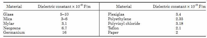
TABLE 2 Dielectric Constants of Some Common Materials
3. Capacitance
3.1 Capacitor formulas
Capacitors store electrical charge, as opposed to cells where the charge is generated by chemical action. Capacitance is a measure of the amount of charge that can be stored. The capacitance of a capacitor is given by C = eA/d (eqn. 14)
where C = capacitance in farads (F)
e = dielectric constant of the material (F/m) between the plates
A = area of the plates (m^2 )
d = distance between the plates (m)
The dielectric constants of some common materials are given in TABLE 2. A 1-F capacitor is defined as a capacitor that will store 1 C of charge when there is a voltage potential of 1 V across the plates of the capacitor (a coulomb of charge is obtained when a current of 1 A flows for 1 s). A farad is a very large unit and microfarad and picofarad are the commonly used units.
Example 8 What is the capacitance between two parallel plates whose areas are 1 m2 separated by a 1-mm thick piece of dielectric with a dielectric constant of 5.5 × 10⁻⁹ F/m?
In electrical circuits, capacitors are used to block dc voltages, but will allow ac voltages to pass through them. Capacitors do, however, present impedance not resistance to ac current flow. This is due to the fact that the current and voltage are not in phase. Impedance is similar to the resistance a resistor presents to a dc current flow, but as they are not identical they cannot be directly added and will be dealt with in Chap. 3.
The impedance of a capacitor to ac flow is given by (eqn. 15)
where XC = impedance to ac current flow
f = frequency of the ac signal
C = capacitance in farads
Ohm's law also applies to ac circuits, so that the relation between voltage and current is given by
E = IxC (eqn. 16)
where E is the ac voltage amplitude and I is the ac current flowing.
Example 9 What is the ac current flowing in the circuit shown in FIG. 7a?
= 1.06 × 10^3 ?= 1.06 kOhm
I = E/XC = 12/1.06 × 103
= 11.3 × 10⁻³ A = 11.3 mA
3.2 Capacitor combinations
The formulas for the effective capacitance of capacitors connected in series and parallel are the opposite of resistors connected in series and parallel.
Capacitors in series are shown in FIG. 7b and have an effective capacitance given by (eqn. 17)
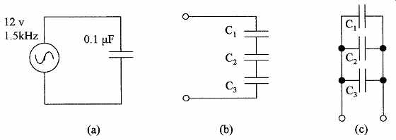
FIG. 7 Circuits (a) used in Example 9 (b) capacitors connected in
series, and (c) capacitors connected in parallel.
Capacitors in parallel are shown in FIG. 7c and have an effective capacitance given by (eqn. 18)
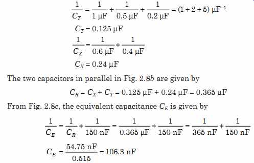
Example 10 What is the value of the capacitor that could be used to replace the capacitor network shown in FIG. 8a? In this example the first step is to reduce the three capacitors in series to a single capacitor and the two capacitors in series to a single capacitor as shown in FIG. 8b.

FIG. 8 Circuits for use in Example 10: (a) circuit used in example,
(b) reduction of series capacitors to single capacitors, and (c) replacement
of parallel capacitors with a single capacitor.
4. Inductance
4.1 Inductor formulas
Inductors are devices that oppose any change in the current flowing through them. The inductance of a coil is given by
(eqn. 19)
where L = inductance in henries N = number of turns of wire m = permeability of the core of the coil (H/m)
A = cross sectional area of the coil (m^2)
d = length of the coil (m)
A henry is defined as the inductance that will produce an emf of 1V when the current through the inductance changes at the rate of 1 A/s.
Example 11 A coil with a diameter of 0.5 m and length 0.7 m is wound with 100 turns of wire, what is its inductance if the material of the core has a permeability of 7.5 × 10⁻⁷ H/m?
Inductive impedance to ac current flow is given by:
XL = 2pfL (eqn. 20)
where XL = impedance to ac current flow f = frequency of the ac signal L = inductance in henries
Example 12 What is the impedance to a 50-kHz sine wave of a 10-mH inductance?
XL = 2pfL = 2p × 50 × 10^3 × 10 × 10^-3 = 3100 ohm = 3.1 kOhm
4.2 Inductor combinations
The formula for the effective inductance of inductors connected in series and parallel is the same as for resistors.
Inductors in series have an effective inductance given by
(eqn. 21)
Inductors in parallel have an effective inductance given by (eqn. 22)
Summary
This section was designed to refresh and expand your knowledge of basic electrical components. The main points covered in this section are:
1. Introduction to the different effects of dc and ac electrical supplies on circuit components
2. Resistivity of materials and their resistance when made into components, the effect of temperature on the resistance of components, introduction to Ohm's law, and power dissipation in resistive components
3. The effective resistance of resistors connected in series and parallel and their use as voltage dividers
4. Discussion of Kirchoff's voltage and current laws, Wheatstone bridge circuits and their use in the measurement of small changes in resistance, and the use of bridge circuits for strain gauge measurement
5. Description of capacitance and the formulas used for capacitors, the effective capacitance of capacitors connected in series and parallel and the impedance of capacitors when used in ac circuits
6. A description of inductance and the formulas used for inductors, the effective impedance of inductors used in ac circuits, and the effective inductance of inductors when they are connected in series and parallel
Problems
1. A radio beacon transmits a frequency of 230 MHz. What is the wavelength of the signals?
2. What is the power dissipation in a 68 ohm resistive load, when a 110-V (peak-to-peak) sine wave is applied to the resistor?
3. The resistivity of a material used to make a round 950 ohm resistor is 53 ohm per unit length. If the resistor has a radius of 0.16 in, what is it's length?
4. A resistor with a temperature coefficient of 0.0045/°C has a resistance of 130 ohm at 20°C. At what temperature will the resistance be 183 Ohm?
5. A dc voltage of 17 V is measured across a 133-ohm resistor. What is the current flowing through the resistor?
6. A dc voltage is applied to three resistors in parallel. The values of the resistors are 7.5, 12.5, and 14.8 kOhm. If the total current flowing is 2.7 mA, what is the applied voltage?
7. The configuration of the three resistors in Prob. 6 is changed from a parallel to a series connection. If the current flowing in the resistors is unchanged, what is the total voltage across the three resistors?
8. What is the supply current It flowing in the circuit shown in FIG. 9a?
9. Calculate the voltage across each of the resistors in Prob. 7. Does the result support Kirchoff's first law?
10. What is the current flowing in each of the resistors in Prob. 6? Does the result support Kirchoff's second law?
11. What is the voltage measured in the bridge circuit shown in FIG. 9b?
12 Two rectangular parallel plates 2.2 m by 3.7 m are separated by a material with a dielectric constant of 4.8 × 10^-9 F/m. If the capacitance between the plates is 4.3 µF, what is the separation of the plates?
13. A3.2 nF capacitor has an impedance of 0.02 M? when an ac voltage is applied to it. What is the frequency of the ac voltage?
14. What is the current flowing in Prob. 13, if the peak-to-peak ac voltage is 18 V?
15. Three capacitors are connected in series. See FIG. 7b. If the values of the capacitors are 110, 93, and 213 pF, what is the value of a single capacitor that could be used to replace them?
16. What is the value of a single capacitor that could be used to replace the capacitors shown in FIG. 10a?
17 An inductor of 2.8 mH is being constructed on a core whose diameter is 1.4 cm and length is 5.6 cm. If the permeability of the core is 4.7 × 10^-7 H/m, how many turns of wire will be required?
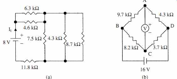
FIG. 9 Diagrams for (a) Prob. 8 and (b) Prob. 11.
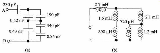
FIG. 10 Circuits for (a) Prob. 16 and (b) Prob. 20.
18. What is the value of inductance that will have an impedance of 11.4 kOhm at a frequency of 2.3 MHz?
19. What value of inductance can be used to replace two inductors connected in parallel, if their values are 4.2 and 8.7 mH?
20. What value of inductance would be used to replace the inductor network shown in FIG. 10b?
Related Articles -- Top of Page -- Home