AMAZON multi-meters discounts AMAZON oscilloscope discounts
A transmitter is a device containing a specialized circuit that can accept any of the signals from sensors such as millivolt, milliamp, voltage, or frequency pulses, and convert it to a 4-20 mA, 1-5 volt, 0-5 volt, or 0-10 volt signal. The electrical diagram of a typical transmitter is shown in ill. 1. In this diagram you can see that the sensor signal is accepted as an input signal in the upper left corner of the circuit. The two-wire sensor signal is sent through a low-pass filter section and a signal amplifier, which is a circuit that contains one or more op amps to provide zero, span, and linearization capabilities. The signal is then sent through an isolation transformer and then to an output amplifier, which conditions the small signal to a more usable 4-20 mA signal. The output section of the transmitter is powered by an external voltage supply (usually 12-20 volts dc). Notice that since the output signal for this type of transmitter is 4-20 mA, the output section will form a series circuit with the external power supply (Vs) and the system that will be accepting the signal. The system that accepts this signal as an input is identified as the load (RL) in the transmitter circuit. Also notice that the transmitter must have its own power supply of 12-50 volts dc to provide power for its electronic components and amplifiers. The diagram in ill. 1a shows an example of an electrical diagram for a two-wire transmitter. The two-wire circuit receives a small voltage input signal and the transmitter converts the signal to a 4-20 mA signal that is usable as the current input signal for recorders or controllers. This type of input signal is called a 4-20 mA loop.
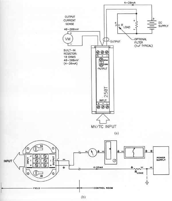
ill. 1: (a) Electrical diagram of a typical signal transmitter that converts
a voltage signal to a 4-20 mA loop signal. (b) A diagram that shows an
ammeter, recorder, and controller connected in series so that they all
receive the same current.
The diagram in ill. 1b shows the types of devices such as recorders and controllers that use the signal from the 4-20 mA loop. One of the main advantages of the current-loop signal is that the current is the same in all parts of the circuit, so each component in the circuit will receive the same signal. This means all the devices in the circuit such as the transmitter, ammeter, recorder, and controller are connected in series. Thus, they will all receive the same amount of current. This is important when all the devices in the circuit must be calibrated. it's also important that all of the devices in the circuit experience a loss of current if an open circuit occurs.
The other advantage of the 4-20 mA signal is that the 4 mA represents a live zero. This means that if the signal from the controller or transmitter ever drops to 0 mA, the circuit wiring or components have caused an open circuit to occur. If the controller or transmitter is trying to send a 0% output signal, the current loop will have 4 mA under normal conditions. Since the current loop can be used to send all components and devices connected in the loop the same amount of current, and the 4 mA offset can be used for a live zero, you will find that it's the most common type of signal used in industrial instruments and sensors.
ill. 2a shows a diagram of a sensor connected to a filter, amplifier, and display as you would find in a typical industrial installation. From this diagram you can see that the sensor requires a power supply to amplify its signal. If a display is used, an additional power supply is required for it. The output signal format is 4-20 mA, which means that the end user of the signal must be connected in series with the output amplifier. The end user of the signal in this diagram is indicated as the load (RLOAD). ill. 2b shows a picture of a transmitter mounted on a DIN rail and two thermocouple transmitters that can be mounted in a cabinet. A DIN rail is a mounting strip that is attached permanently to an electrical panel, and components such as transmitters can be mounted to the rail so that they can easily be removed and replaced if they need to be tested or changed.

ill. 2 (a) Diagram of a typical sensor connected to filters, amplifiers, and displays.
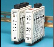 |
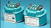 |
ill. 2. (b) Examples of signal transmitters that are mounted on DIN rails and three transmitters that can be mounted directly into any cabinet.


