AMAZON multi-meters discounts AMAZON oscilloscope discounts
Since most sensors provide a very small signal, it must be amplified or compared before it's of any use. The bridge circuit is used to compare the signal to some setpoint (SP) value and the op amp circuit is used to amplify any sensor signal that is too small. The Figure below shows a temperature sensor that changes resistance with changes in temperature. This sensor is called a resistive temperature detector (RTD) and it's connected to a bridge circuit. The variable resistor in the bridge is adjusted to provide a setpoint. If the temperature changes, the resistance in the RTD will change in proportion and the voltage through the bridge will reflect this change. Since the temperature can increase or decrease, the voltage at the bridge can swing to positive or negative. it's important to understand that any resistive sensor can be used in a bridge circuit.
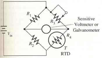
Above: Diagram of a resistive temperature device (RTD) connected to a bridge
circuit.
Another circuit that is widely used with sensors is the op amp circuit. Since sensors provide a voltage signal or a change in resistance, the op amp circuit must be able to amplify either voltage or resistive signals. The Figure below shows the op amp circuit with a photoconductive cell as its sensor. In this circuit, the sensor must also have a voltage supply. When light strikes the photoconductive cell, its resistance will change. Since this resistance is actually Rin for the op amp circuit, it will change the gain of the op amp when the resistance changes. When the gain of the op amp changes, it will change the output voltage of the op amp.
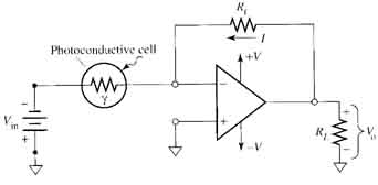
Above: Diagram of a photocell that changes its resistance when light strikes
it. The resistive sensors require a voltage supply.
The op amp must also be able to amplify signals from sensors that change voltage rather than resistance. The Figure below shows a circuit with a solar cell (photovoltaic cell) connected to the op amp circuit. When light strikes the solar cell, it will change voltage, and the op amp will amplify the small-signal voltage. This is the typical circuit that will be used for all sensors that produce small voltages.
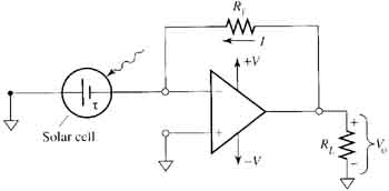
Above: Diagram of a photoconductive cell that is connected to an op amp.
Since the photoconductive cell produces its own voltage, it does not
require an additional voltage source.
Previous Page: Analog and Digital Signals | Next Page: Transmitters