Before you test any tubes or other parts in your antique radio, check the cables (speaker, antenna, etc.) and plugs for good connections and for continuity. Then isolate the trouble to a particular stage or tube as explained in the preceding Sections. If you have done your troubleshooting diligently, you should have a good idea of which tube or other part is at fault, and you shouldn’t have to check too many parts before you find the one that needs replacing or repair.
For testing parts, you will need a low-cost general-purpose instrument called the volt-ohm-milliammeter (VOM), or multimeter. Such an instrument is useful for measuring the resistance of parts and checking for short and open circuits. It is also useful for measuring battery voltages, tube DC voltages, and such AC voltages as filament voltages and audio output. The most important specification of a VOM is its sensitivity, measured in ohms per volt. Try to get a meter with an ohms-per-volt rating of at least 20,000 ohms per volt, such as the Triplett model shown in FIG. 1.
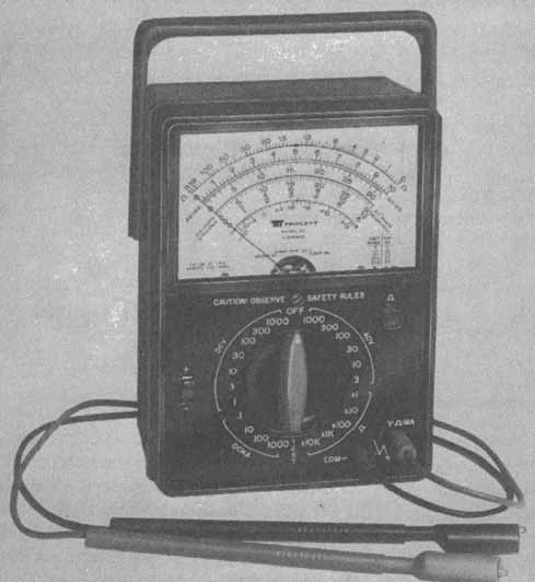
Fig. 1. A 20,000-ohms-per-volt multimeter such as this is desirable
for testing antique radios (from Tnplett Company).
Once you have been restoring radios for a while, you may want to acquire additional equipment. Probably the next piece of equipment to buy is an electronic multimeter. This instrument is capable of measuring higher resistances than a VOM—for example, the 0.5 to 5 megohms of the grid-leak resistors found in some sets. Further more, an electric voltmeter can measure the voltages in high- resistance circuits more accurately than a VOM (though for low-resistance circuits a VOM is just as good).
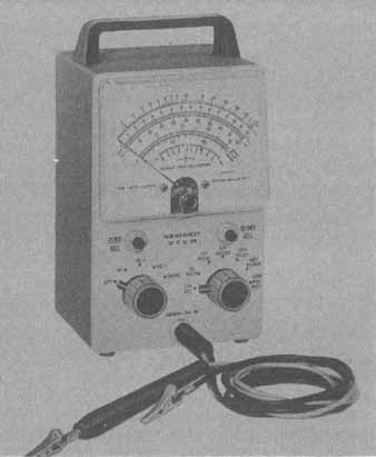
FIG. 2. After a VOM, the next piece of test equipment to buy is an electronic
voltmeter such as this one. This VTVM from Heath Company is a low-cost electronic
multimeter.
The original type of electronic multimeter was the VTVM. One model VTVM is the Heathkit Model IM-18, shown in FIG. 2. Solid-state multimeters are also available. An example is the Heath- kit Model IM-5225, shown in FIG. 3. These meters are more expensive than vacuum-tube versions, but they are more stable, more reliable and more portable. They feature cordless operation and measure current as well as resistance and voltage.
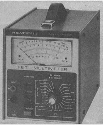
FIG. 3. This FET (field-effect transistor) multimeter is an electronic multimeter
from Heath Company. This solid-state meter is more desirable than the vacuum-tube
type if you can afford it.
Before removing any tubes, turn on the power to see whether they warm up properly. If the envelopes are of glass, a visual inspection will show whether any are burned out. If the tube envelopes are of metal, turn off the power before attempting to feel them with your fingers. One-volt or other low-current metal tubes, however, will not generate sufficient heat to do this.
If a tube tester is available, first turn off the power, and then remove and test the tubes one at a time. Substitute new tubes only for those that are shown to be definitely defective. If a tube is suspected of being intermittent, it should be tapped gently while being checked, to bring out any defect.
If a tube tester is not available, and modern testers may not test some very old tubes, troubleshoot by the tube substitution method.
TUBE CHECKING BY SUBSTITUTION
Replace the suspected tubes with new tubes one at a time. If the radio begins to operate normally, discard the last tube removed, and return the other original tubes to their sockets. Some circuits, such as some oscillator circuits, may operate with one good tube and not with another. This is because of the difference in the interelectrode capacitance between the tubes, which plays a large part in determining the resonant frequency. Therefore, if a tube does not operate in an oscillator circuit, do not discard it until it is known to be definitely bad.
Caution:
By rocking or rotating a tube, you could bend the pins, break the weld wire where the pin enters the glass, or—even if the weld does not break—cause a high-resistance joint to develop. Before handling large tubes, allow them sufficient time to cool.
In some cases, it is possible to remove a tube from one section of the equipment without affecting the section being checked. In such a case, it is possible to troubleshoot the defective section by using a tube—the same type, of course—from another section as a substitute, if sufficient spares are not available.
Note that if a replacement for a bad tube becomes defective immediately, check the component parts in that circuit.
If a component has more than one bad tube at the same time, substituting tubes one at a time and reinserting the original tube before substituting for a second tube will not locate the defective tube. The original tube may have been defective, but it was not evident because there is another defective tube that is preventing normal operation. To correct this trouble, install new tubes and keep putting in new tubes until normal operation is restored. The last tube replaced is defective and should be discarded. To determine whether another original tube is bad, return an original tube to its socket. If there is a noticeable change in operation, discard the last original tube installed. Another method is to install all new tubes, then replace them with the original tubes, one at a time. When failure or change is noticed, discard the last original tube installed. Do not leave a new tube in a socket if the equipment operates satisfactorily with the original tube. If not one of the above procedures restores the receiver to normal operation, further troubleshooting is necessary.
A tube should never be discarded unless a tube tester or other instrument shows it to be defective, or it can be seen that the tube has a broken glass envelope, an open filament or a broken base pin. Do not discard a tube merely because it has been in operation for a long time. Satisfactory operation in the equipment is the final proof of tube quality.
CHECKING SERIES FILAMENTS
Tube filaments connected in series present a problem. An open filament in a tube will cause all other filaments in the string to go out. This makes it difficult to detect a burned-out tube quickly.
One way to test the tubes for open filaments is to remove them one at a time and check the filaments for continuity with an ohmmeter, but this procedure usually takes too much time. In addition, it can cause burnouts in the 1-volt or other low-current tubes. The ohmmeter should be set on a scale other than the lowest, because the current the ohmmeter can pass through the tubes on its lowest scale is sometimes high enough to bum out the filament.
If the bottoms of the tube sockets are accessible, the tube with the open filament can be found by measuring the voltage across the tube filament terminals with all tubes in their sockets. All good tubes in the string will measure zero voltage across their filaments, but the one that is burned out will have the full voltage that is applied across the string ( FIG. 4). The open filament will have 6 volts across it. If any one tube in FIG. 4 has 1½ volts across it, all filaments are good, because the 6 volts will be divided equally among the four tubes.
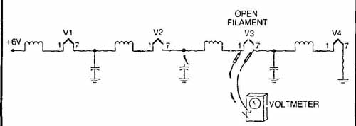
FIG. 4. Finding open filament with a voltmeter.
Radios using series-parallel filament circuits often have shunting resistors across some tube filaments in the series circuit to maintain the correct value of current flow in each tube. In this type of circuit, the voltage measured across a burned-out filament may be nearly the same as the voltage across a good tube. This is because the shunt resistor may be intact and why measurements should be made carefully and not too rapidly.
TESTING PARTS
When the trouble has been narrowed down to a section and then to a stage by using test equipment or simple short-cut methods, the trouble must be pinpointed to the defective part. This means testing the suspected parts—resistors, capacitors, or inductors. In many cases, the testing can be accomplished with a multimeter. This procedure is useful whether the parts are mounted in a unit or have been removed.
CHECKING RESISTORS
Before checking the suspected resistor with an ohmmeter, the circuit should be examined to determine whether it is necessary to disconnect one lead of the resistor. If it is shunted by another part that can form a DC path, the resistance indicated will be lower than the actual resistance of the resistor, because the total resistance of two or more resistances in parallel is less than the resistance of the lowest value in the branch. When the resistor is disconnected, it can be checked for continuity and resistance. It is advisable to use the ohmmeter range that will give a midscale reading to insure accuracy.
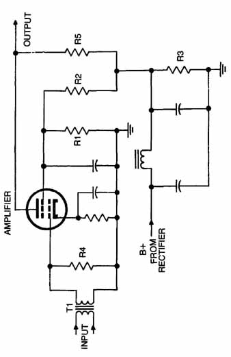
FIG. 5
In FIG. 5, resistor R4 is shunted across the grid winding of transformer T1. If a continuity measurement is made across R4, the low-resistance path through T1 in parallel with R4 will be indicated on the ohmmeter and an erroneous reading will result. It is therefore necessary to disconnect R4 at one end before checking it. Plate load resistor R5 has no parts in parallel with it and can be checked while it is in the circuit. The resistance from the screen grid to ground is measured through R1, which is in parallel with R2 and R3 in series. If the resistance and voltages are different from the specified values, any one of the three resistors could have changed in resistance. To check one of these parts, disconnect one end of it from the circuit.
It is important to use the right scale of the ohmmeter when measuring resistance or continuity. If a high range is used, a low- resistance part or a poor connection will show up as a full-scale or a closed-circuit reading. Use the high range only when checking high- resistance circuits. If a low range is used, a fairly high resistance will give the same reading as an open circuit. The resistance value will be known approximately, either by its markings or circuit information; therefore, you should use the range that will give approximate half-scale indications. Another precaution is to be sure that the fingers do not touch the ends of the test prods, because the resistance of the body will cause an inaccurate indication on the ohmmeter.
Sometimes a resistor will have normal resistance when it is cold, but will change value as its temperature rises. Measure the voltage across it as soon as the power is turned on, and also after it warms up. If the voltage changes considerably over a short time period, the resistor is changing in value and should be replaced.
If voltage or resistance tests indicate that a variable or adjustable resistor may be defective, a final test will have to be made, and for this purpose two of the three leads will have to be disconnected, thus effectively isolating the suspected resistor from the rest of the set. To check the resistor then, measure the resistance from one end to the other and from the top to each of the two ends separately. To test for breaks that show up only as the resistance is varied, slide the moveable member back and forth while testing it.
A resistor measured with an ohmmeter will usually measure a small amount higher or lower than the marking or color code specifies. This is because of the tolerance of the resistor. For example, a 1-megohm unit with a 20-percent tolerance will measure anywhere from 800,000 ohms to 1,200,000 ohms. In addition, the ohmmeter will not be 100-percent accurate, and its deviation from accuracy can cause a further error in measurement. A resistor having a tolerance of 5 percent is marked with a gold band and one with a tolerance of 10 percent is marked with a silver band. Resistors of greater tolerance are not marked.
TESTING COILS AND TRANSFORMERS
Coils and transformers include RF and audio chokes, power transformers, relay coils, audio transformers, IF transformers and coils and any component that is wound with wire, except wire-wound resistors. These items should be checked for resistance values and the readings compared with the normal values. If necessary, one lead should be disconnected to prevent errors in readings. If the readings look suspicious, you should check each winding for shorts or leaks to ground, or a leak to another winding within the same component.
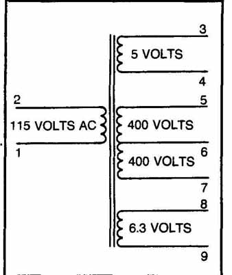
Fig 6. Power-transformer windings.
Refer to FIG. 6 for an example of a power-transformer-winding schematic diagram. TBL. i shows the check points, normal readings and the points to check for shorts.
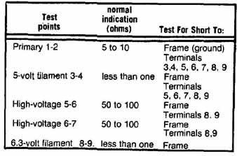
TBL. 1. Power-transformer resistance chart.
The condition of low-voltage windings is often difficult to determine because usually the resistance is so low that the readings appear as short circuits. However, don’t suspect these windings of short circuits unless there is a blown fuse or severe overheating of the transformer. These windings rarely open because the wire is so heavy that a fuse will blow before the winding opens. One method of testing a power transformer for shorts is to connect a 115-volt lamp of 50 to 100 watts in series with the primary winding. If the line voltage is 220 volts, a 220-volt lamp must be used. Remove all tubes to take the load off the secondaries.
Turn on the power. If the lamp lights brightly, the high-voltage secondary winding is probably shorted. If the condition existed only after the power had been turned on for some time, the test will not show the trouble immediately. It will then be necessary to run this test for several minutes to an hour. If the short circuit takes time to develop, the lamp will glow when the defect appears. This test does not apply to a defective primary. If the primary were shorted, the line fuse would have blown. The troubles that will cause the lamp to glow will therefore be in the secondary windings. If the lamp lights only when the tubes are in their sockets, the transformer is not at fault.
The windings used in RF and IF amplifier stages are subject to some of the defects found in power transformers. The windings can be tested for open circuits with an ohmmeter. They rarely develop short circuits, but if they are suspected, resistance checks can be used to detect them. When a coil has a very low normal resistance, the available ohmmeter may not be able to indicate accurately the difference between a normal and shorted coil. The only way to be sure is to install a new part. This information applies also to RF choke coils.
CHECKING CAPACITORS
A capacitor can fail in several ways. It may become shorted, develop a leak or an open circuit, or change its capacitance. A multimeter or VTVM can check most leaks or shorts. However, you must use a capacitor checker or AC meter to detect a change in capacitance. If you believe the capacitor open, a good method of double checking it, while it is in the circuit, is to bridge it with a capacitor known to be good.
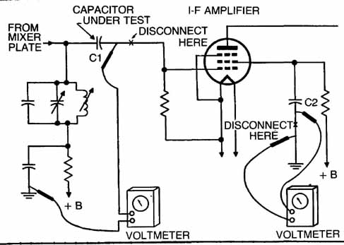
To determine whether a capacitor is leaky or shorted, disconnect it from the circuit and test is with an ohmmeter. There are occasions when a leak will not show up unless the capacitor is subjected to the voltage appearing in the set; therefore, the ohmmeter test will not indicate a defect. Disconnect coupling capacitor C1 in FIG. 7 at the low-voltage side. Connect the voltmeter between the free end of the capacitor, ground the set and turn it on. If there is a short or leak in C1, part of the DC voltage applied to the other side of C1 will be indicated on the voltmeter.
A suspected bypass or filter capacitor (C2 in FIG. 7) should be disconnected at the ground side. Connect the voltmeter between the low side of C2 and ground ( FIG. 8). With the set turned on, part or all of the screen-grid voltage will be indicated on the meter if C2 is leaky or shorted. Use an ohmmeter to test the capacitor, but turn the power off first.
Whenever a capacitor, such as C1 or C2 in FIG. 7, is suspected of being open, the quickest way to check it is to shunt a good capacitor across it ( FIG. 9).
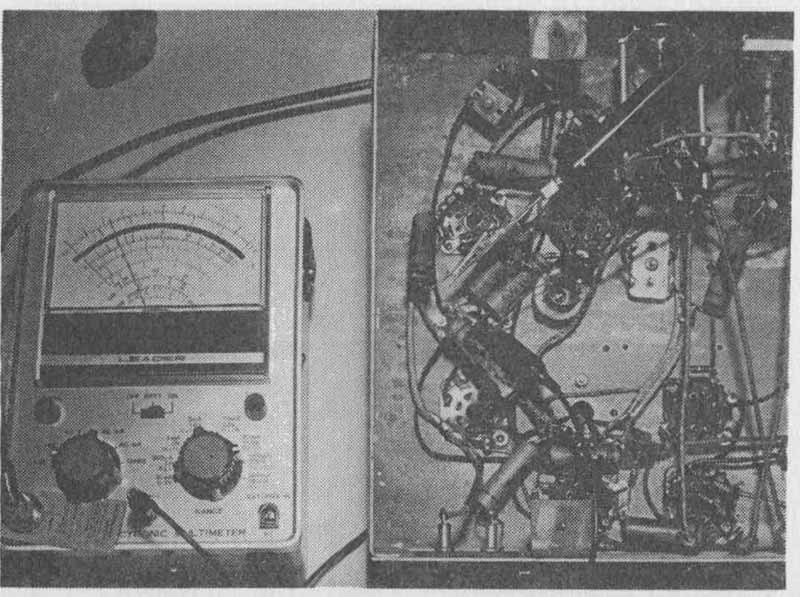
FIG. 8. Checking for an open capacitor.
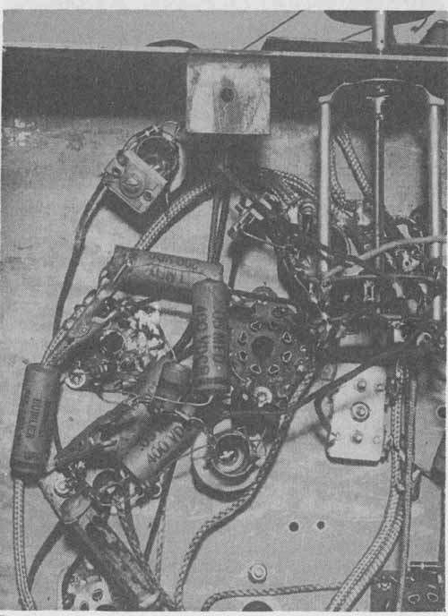
FIG. 9. Shunting a good capacitor across a questionable one.
Capacitors of comparatively large values, such as electrolytics, can be tested for open circuits with an ohmmeter. Be sure to connect the positive lead of the meter to the positive lead of the capacitor. Connect the ohmmeter terminals across the capacitor terminals and watch the meter needle. If the capacitor is good, the needle will rise rapidly as the capacitor is charging, and will fall slowly as the capacitor becomes charged.
Another test is to connect the capacitor across a source of DC power where the voltage is equal to, or less than, the DC voltage rating of the capacitor. If the capacitor is polarized, be sure to connect the plus side to the plus side of the power source. After a few seconds of contact, remove the capacitor and bring its terminals close together. If a spark results, the capacitor is not completely open.
Capacitors may change in value, thereby producing abnormal results. To check the capacitor accurately, it is necessary to disconnect one end or remove it entirely and check it with a capacitor checker. Electrolytic capacitors lose capacitance with age because the electrolyte dries out.
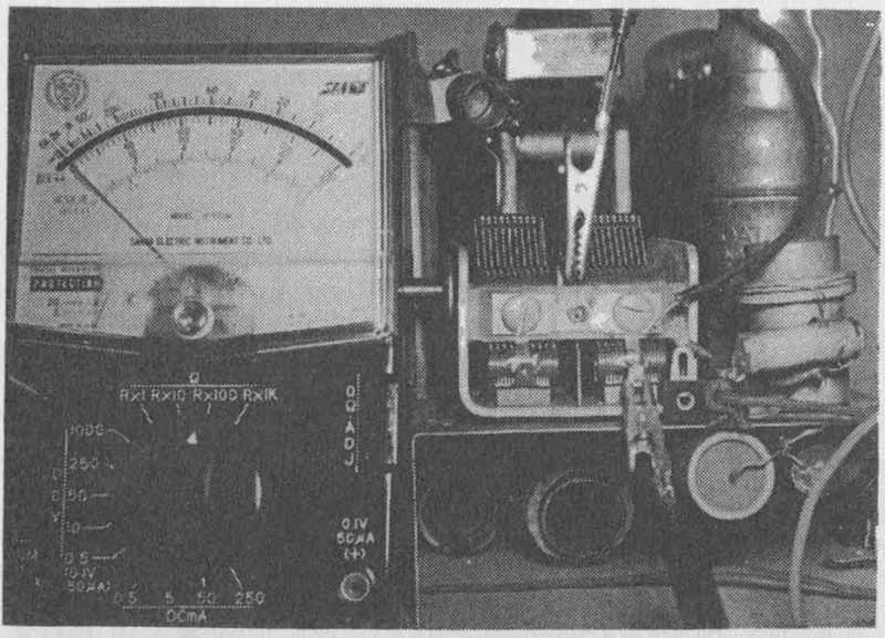
A variable tuning capacitor or air trimmer can become shorted or leaky. To test for either condition, one end of the capacitor must be disconnected from the circuit to prevent a DC path through a coil or other part. The operation is the same as for other capacitors; that is, the ohmmeter test leads must be connected from one set of plates to the other. Any accidental bent plates must be straightened and foreign matter removed from between them. While observing the meter needle, move the rotor plates through their complete range ( FIG. 10). When the abnormal condition has been remedied, the ohmmeter will read infinity.
