In restoring old-time radios, we are often confronted with a dilemma. One part of the dilemma is the unavailability of replacement parts. The other part is the impossibility or impracticality of repairing some parts. The solution is substitution. Substitution is particularly applicable to tubes, which cannot be repaired. The information in this Section shows which tubes can be replaced by which other tubes and what changes—if any—must be made to circuit wiring to accommodate the replacements. The Section includes a Mini- Manual of Old-Time Tubes, which will allow you to compare old-time tubes to see which are interchangeable. The Section also includes much other information about substituting for tubes and other parts.
TUBE SUBSTITUTION
If a tube is not available to replace one that is defective, a substitute must be used. However, the equipment probably will not operate as well as it did with the original tube and considerable labor may be involved. Do not put a substitute tube into a socket unless the substitute tube characteristics and socket connections have been compared with those of the original tube (refer to the Mini- Manual of Old-Time Tubes), If this procedure is not followed, the filaments may burn out or the power supply may be short-circuited.
A tube of similar electrical characteristics may prove a more or less effective substitute depending upon the purpose for which it would be used. A power tube would not be used to replace a voltage amplifier because the filament and plate current drain (see Mini- Manual) would probably be excessive. If the tubes are wired in parallel, a slight difference in filament current rating will not matter. If the filaments are in series, the filament drain must be the same for all tubes.
A tube of similar electrical characteristics may be physically different from the original tube. If it is considerably larger, it may not be usable. If it has a different type of base (see Mini Manual), the socket will have to be changed to make it available for use.
Tube substitution in critical RF amplifier and oscillator circuits may necessitate the realignment of the circuits.
TBL. 1 is a ready reference of the tube substitutions that I have found easiest and most likely to succeed. In each case, the substitute tube fits the same socket as the original tube and takes the same filament voltage. No wiring changes are required, but there may be some differences in gain, internal capacitances, filament current and other characteristics. In going from a metal to a glass tube, you may have to install a shielding can on the glass replacement tube.
For more information about tube substitutions, refer to the sections Data and Uses of the Tube Manual and Use of the Mini- Manual or Old-Time Tubes.
DATA AND USES OF THE TUBE MANUAL
Information in the tube manual is often helpful to the radio restorer. Suppose, for example, you have a defective 6A7 type tube for which you must find a substitute. There is no direct substitution possible for this tube, so it is not listed in TBL. 1. However, the RCA Receiving Tube Manual excerpt in Section A shows that the type 6A8 is electrically equivalent to the 6A7 and requires only the replacement of the 7-prong socket with an 8-prong socket.
USE OF THE MINI-MANUAL OF OLD/TIME TUBES
The Mini-Manual of Old-Time Tubes, incorporated in this volume as a guide within a guide, is a guide to the tubes used in old-time radios, As such, it is a unique aid to the restorer or collector of old-time radios. The Mini-Manual will allow you to compare the various old tubes to determine which are interchangeable and what wiring changes are required. ( TBL. 1 shows the substitutions for which no wiring changes are required.)

FIG. 1 Base connections of old-time tubes, looking from the bottom of the
tube. Sketch references such as 4-1 are referred to in Base column of the Mini-Manual
of Old-Time Tubes. Small centered circles drawn in dashed lines denote plate
cap or grid cap. Electrode symbols are: D, diode plate; F, filament; G, grid;
G1, Inner grid; G2, screen grid; G3, suppressor grid; H, heater; K, cathode;
NC, no connection; P, plate.

TBL. 1. Ready reference of easiest and most successful tube substitutions.
Original Tube | Replacements for Original Tube
The first thing to look for in determining interchangeability is whether the tubes have the same base connections. FIG. 1 shows the base diagrams for the various tubes in the Mini-Manual. In the Mini-Manual the type of base is indicated by two figures, which are keyed to the drawings in FIG. 1.
In some AC-DC sets, the filaments are wired in series. There is no transformer to drop the line voltage to the filament voltage.
Instead, the filaments and a series resistor are connected directly across the AC line. For this scheme to work, a substitute tube must have approximately the same cathode current (filament drain) as the original tube. Even with some transformer-powered AC radios in which the filaments are in parallel, the filament current drain may prevent some tubes from being used as substitutes, because the current drain may be more than the transformer can handle.
The voltages of other elements are not as critical as the filament voltage, but improper plate, screen or grid voltage can cause weak or distorted reception. Excessive plate current drain can overload the transformer, and can also cause immediate or premature failure of the tube or other parts. Insufficient grid bias (not negative enough) can cause excessive plate current, as can using a tube with too high a rated plate current.
SUBSTITUTE FILAMENT AND PLATE TRANSFORMERS
If a transformer is defective and an exact replacement is not available, a similar transformer may be used if its electrical characteristics and connections are known. Such information can be found by using an ohmmeter and AC voltmeter. The ohmmeter and volt meter may be combined in a multimeter or VTVM.
If the proposed substitute is too large to be installed in the space that was occupied by the original transformer, it may, in an extreme emergency, be connected externally. You must also determine whether the replacement transformer has the proper power rating.
Most transformers have terminals which are usually numbered. If a diagram of the windings and terminals appears on the transformer, the identification will be simple. If there is no diagram, the windings can be identified by their resistances and voltage tests described below.
Some transformers have leads instead of terminals. If the leads are color coded, they can be identified by comparing the colors with those in TBL. 2. Although this code is standard, other codes pertain in some cases.
The windings on the transformer with leads can be identified by visual inspection and by the thickness of the leads. The thicker leads are from the filament winding because the filaments draw more current than other circuits. In some transformers, there will be two or three filament windings: one for the rectifier filaments and the others for the other filaments. The rectifier filament usually draws less current than the other tube filaments combined.
The high-voltage winding carries the least amount of current, so the leads to it will be the thinnest of all. The primary winding is also thin; the difference can be determined by resistance measurements. Connect one ohmmeter prod to one lead and check for continuity to all other leads one at a time. The high-voltage winding will have the highest resistance, and the primary winding will have the next highest resistance.
A further check can be made with an AC voltmeter. When the primary winding has been found by the tests described above, connect it to the AC power line. Set the voltmeter to the highest range and measure the voltage across the thinnest leads. There probably will be three wires; the third one is the center tap in the case of a full-wave rectifier circuit. The highest voltage will appear across the ends of the winding. If one-half of this value is measured between either one of the end leads and another lead, the other lead is the center tap. The filament windings will show about 5 or 6 volts, depending on whether the winding being measured is the rectifier filament or the other filament winding.
There are some rectifier filaments that require 6.3 volts, rather than 5 volts. In this instance the winding with the thinner wire usually is the rectifier filament winding. If they are about the same size, and a low-reading ohmmeter does not show any difference, the leads with the heavier insulation feed the rectifier filaments. This is because this winding is usually at a high potential with respect to the chassis.
Some power transformers have thin leads in addition to the leads described above. They are probably taps on the primary winding. Such taps are provided so that the proper secondary voltages will be produced regardless of the line voltage. Continuity checks will show whether they are connected to the primary end leads. The highest resistance will be indicated between the extreme ends of the primary winding; the next highest reading will be indicated between the next highest voltage tap and the other end. If in doubt about which taps to use, connect the lead that indicates a high resistance to all the other taps to one side of the line, and one of the taps to the other side of the line. Measure the filament voltage under load. If it reads too high or too low, select another tap until the reading is about right. As long as the line voltage remains fixed around the same value, the connections can be made permanent.
TBL. 2. Power-Transformer-Lead Color Code.
Leads | Colors
Primary If tapped: Common Tap Finish High-voltage plate Center tap Rectifier filament Center tap Filament No. 1 Center tap Filament No. 2 Center tap Filament No. 3 Center tap
|
Black Black Black and yellow stripes Black and red stripes Red Red and yellow stripes Yellow Yellow and blue stripes Green Green and yellow stripes Brown Brown and yellow stripes Slate Slate and yellow stripes
|
Filament and plate transformers are treated the same as power transformers. There are only two windings, the primary and secondary. Some transformers of this type may have center-tapped secondaries. The filament leads will be much heavier than the primary leads. In a plate transformer, the high-voltage winding will have a greater resistance than the primary winding.


FIG. 2. Color code for transformers.
FIG. 2 summarizes the color-code information about power transformers and also shows the color codes for IF and interstage audio transformers. It also shows the colors that are sometimes used in chassis wiring for the purpose of circuit identification. These standards are not always adhered to, especially in the older sets.
SUBSTITUTE FOR BALLAST OR UNE CORD RESISTOR
Back in the early 1930s, probably because of the Great Depression, the hard-pressed radio manufacturers sought a way to reduce the cost of their radios so that more people could afford them. They hit upon the idea of eliminating the expensive power transformer by connecting the tube filaments in series, directly across the AC line ( FIG. 3). Of course, anything that is connected across the AC line has to drop (have a voltage rating of) 115 volts. To help drop the 115 volts, tube manufacturers brought out tubes with filaments rated at 25 volts or higher. A typical tube lineup in such sets was as follows: 6A8, 6K7, 6116, 6F5, 25A6 and 25Z6. The filament voltages ac counted for 74 volts of the 115-volt line voltage (6 +6+6+6+25 + 25 = 74). This left 41 volts (115— 74=41) to account for. To drop the 41 volts, the manufacturers added a resistance in series with the filaments to take care of the 41 volts. This resistance sometimes took the form of a length of heater wire enclosed in a glass bulb that was mounted on a tube base. These ballast tubes, as they were called, so resembled regular receiving tubes that some manufacturers couldn’t resist the temptation to include them in the tube count for advertising. Some “8-tube” sets actually had only five operating tubes plus three ballast tubes. Interestingly, this practice of exaggerating the tube count had a sequel in the early days of transistor radios when transistors used as diodes were sometimes included in the transistor count.

Fig. 3. Series tube filaments.
Sometimes the voltage-dropping resistance wire was enclosed within the line cord of the receiver ( FIG. 4). Usually it was wound around an asbestos rope and covered with an insulating sheath. Then it was combined with the other two wires inside a rubber sheath, which was in turn covered with a woven cotton sheath. These resistance cords ran very warm and deteriorated faster than ordinary cords.
The radio restorer is often faced with the necessity of substituting for a non-available resistance cord or ballast tube. To do so requires a resistor of the proper resistance to drop the voltage in excess of that required by the filaments. The resistor must have sufficient power-handling capability to dissipate the heat generated by the current that will flow in it.
To calculate the resistance, begin by adding all the filament voltages. In the example, they total 74 volts. Next, subtract this from the live voltage (115 volts) to determine the amount that must be dropped by the voltage-dropping resistor. In this case, 41 volts must be dropped by the resistor. The next step is to determine the filament current of the tubes, which the tube manual (see Section B) shows is 0.3 ampere. Now you have enough information to find the resistance, which by Ohm’s law is the voltage (41 volts) divided by the current (0.3 ampere). This is calculated as follows:
R= Volts/amperes = 41/0.31=137 ohms (approximately)
The nearest standard resistance value is 150 ohms.
To calculate the required power rating for the resistor, use the voltage and current determined above; only this again time, multiply instead of divide.
P = volts x amperes = 41 x 0.3 = 12 watts (approximately) There are 12-watt resistors available, but a better choice would be 15, 20, or 25 watts. A larger power rating provides a safety factor. A
150-ohm, 20-watt Ohmite Brown Devil would work fine. Be sure to mount the resistor away from cabinet and circuit parts susceptible to heat damage.
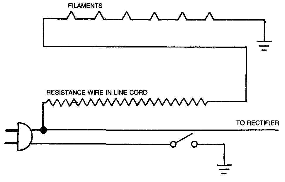
FIG. 4. The old sets often had a length of resistance wire in the line cord.
These resistance cords are often defective.
LOUDSPEAKER
The old-time sets generally used a large electrodynamic speaker with a field coil winding that was in series with the plate voltage. FIG. 5 shows the connections of this type of speaker. Because the field coil was in series with the plate supply, it acted as the filter choke of the supply. Since the field coil was matched to the other components in the power supply, it is best to repair the speaker, rather than replace it.
FIG. 4. The old sets often had a length of resistance wire in the line cord.
These resistance cords are often defective.

FIG. 5.
Another type of speaker is found in some radios, especially newer ones. This is the permanent magnet type, illustrated in FIG. 6. In these a permanent magnet takes the place of the field coil and electromagnet. Chokes are available from electronic supply stores and mail order houses. The choke you select should have an inductance of 7 henrys or so at 100-200 milliamperes.
It is sometimes possible to repair loudspeakers. A tear in the paper cone of a speaker is usually repairable with a small piece of masking tape. Be careful you don’t make the tear worse, as old speaker cones usually become brittle with age.

FIG. 6. Standard pin arrangement and color code for permanent magnet speakers
used in some sets.
Occasionally the voice coil of a speaker will rub against the pole piece of the magnet, causing rattles and distortion. Usually you can re-center the voice coil and stop the rubbing.
In testing an old speaker, note that the field coils of old speakers will read 500-2000 ohms on an ohmmeter, and voice coils 8 ohms. Recently made speakers may read 3-6 ohms. New headphones may read either a very low resistance (3-6 ohms for dynamic speaker types) or a very high impedance (almost infinity for crystal types). These new speakers and headphones are not suitable for use with old radios designed for a headphone resistance of 1000-2000 ohms. It is possible to match one of the new low-impedance speakers to the plate resistance of the audio output of an old radio by using a new audio transformer. The secondary impedance of the audio transformer should be the same as the voice coil impedance (3-4 ohms in some new speakers, 6-8 ohms in others). The primary impedance of the transformer should approximate the load resistance (impedance) of the audio output tube (last audio tube). Look up the load resistance in the Mini Manual or in the tube characteristics section of Section B.

FIG. 7. Resistor color codes: body-end-dot (top) and bands (bottom).
SUBSTITUTE RESISTORS AND CAPACITORS
In some instances a resistor or capacitor of a certain value may not be obtainable and a substitute part must be used. An application of Ohm’s law will quickly determine the correct value of resistors or capacitors that can be used in series or parallel to replace the original part. For example, if a 1000-ohm, 2-watt resistor is required but not obtainable, use two 500-ohm, 1-watt resistors in series, or two 2000-ohm, 1-watt resistors in parallel. In the case of capacitors, if a 1-uF, 400-volt capacitor is required, either two 2-uF, 200-volt capacitors in series can be used, or two 0. 5-uF, 400-volt capacitors in parallel.

FIG. 8. The dot color code for the mica and molded paper capacitors found
in old radios.
In general, the total resistance Rt of two resistors in series is given by:
Rt=R1=R2
The total resistance of two resistors in series is given by:
Rt=R1+R2/ R1x R2
The total power rating of resistors in series or parallel is simply the sum of the individual ratings.
Capacitances in series add as do resistors in parallel; that is:
C1 + C2
C
C1 x C2
Capacitances in parallel add as do resistances in series; that is Ct = C1 + C2
The voltage rating of capacitors in parallel is the same as that of the capacitor with the lowest voltage rating. The voltage rating of capacitors in series is the sum of the individual ratings.
Some of the resistors and capacitors used in the old-time radios are different from modem parts. To help you determine the electrical values of these parts, FIG. 7 through 11 give the color codes for the old parts (as well as new ones).
FIG. 7 shows the markings on two types of resistors. FIG. 8 presents the dot color code for the mica and molded paper capacitors that you find in the old sets. FIG. 9 shows the 5-dot color code that was used on capacitors with various dielectrics. FIG. 10 gives the 6-band color code for tubular paper dielectric capacitors. And FIG. 11 shows the color code for ceramic capacitors of various configurations. These figures should help you identify almost any resistor or capacitor that was marked according to some standard code.
MINI MANUAL OF OLD-TIME TUBES
The following table gives characteristics of various old radio tubes. The tubes are designated by number. Only the last two figures are required to identify the tube. For example, tube 301-A or 201-A appears in the table as 01-A. The type of base (illustrated in FIG. 1) is indicated by two figures, the first of which is the number of pins. These are mainly tubes used in the oldest radios (before 1935), and many of them are obsolete. For a more complete listing of tubes, including possible substitutes for the tubes in this table and tubes used in sets up to about 1950, refer to the date from the RCA Receiving Tube Manual in Section A.

FIG. 9. The five-dot color code that was once used on capacitors with various
dielectrics.
FIG. 10. The six-band color code for tubular paper-dielectric capacitors.

FIG. 11. Color code for ceramic capacitors having various configurations.