AR SYSTEM DRIVES NEW TURNTABLE
(also see Acoustic Research Turntable (Equip. Profile, July 1984))
TURNTABLE CONSTRUCTION projects have always been a rarity in the audio press. Even the most avid audio equipment builders have usually settled for commercially available turntables, despite their deficiencies and the expense of high-quality units. This article is an attempt to fill that void.
The turntable described here uses the drive system components (motor, belt, platter and sub-chassis) from the classic Acoustic Research (AR) Model XA. It retains the positive aspects of the AR design and corrects its weak nesses. The completed turntable, with a Mayware Formula IV, Mark II tonearm, is shown in Fig. 1.
Belt vs. Direct
No doubt most of you are aware of the continuing debate over belt versus direct-drive systems. From a technological standpoint, direct-drive designs appear to have greater speed accuracy, at least as far as established measurement techniques are concerned. Critical listeners, on the other hand, often find the sound of high-quality belt-drive designs to be far less colored and more musically natural than direct-drive designs using identical arms and cartridges.
Immunity to acoustic feedback in the audible range is, perhaps, the greatest virtue of belt-drive systems using three-spring suspension.
(Among these are the AR, Thorens and Linn systems.) Nearly all direct drive turntables have relatively stiff suspensions and are far more susceptible to acoustic feedback problems.
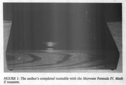
FIGURE 1: The author's completed turntable with the Mayware Formula IV, Mark IT tonearm.
A notable exception is the Goldmund turntable from France, but its $2,500 price tag makes it of little more than academic interest to most music lovers. The belt-drive turntable's suspension also isolates the platter from the motor's vibrations, which is impossible with the direct-drive approach (although a direct-drive motor admittedly vibrates at a far lower frequency and a lower level).
A belt-drive turntable with a heavy platter probably also has a smoother platter rotation than a direct-drive turntable. This is due to the belt driven platter's not being constantly monitored and corrected. Some critics of the direct-drive approach have speculated that the constant correction of the platter's rotation actually frequency modulates the information on the record. This has yet to be proved, though.
These differences are not reflected in conventional rumble, wow and flutter specifications. Even today's worst belt and direct-drive turntables do not suffer from audible rumble or speed variations, as measured by accepted techniques. There are, of course, many audiophiles who claim that turntable drive systems produce no sound of their own, therefore no audible differences exist between units. I do not agree with this assessment.
A belt-drive system will not per form up to its capability unless several areas of design are properly executed:
The three-spring approach to suspension is a must in maintaining proper isolation from acoustical feedback.
The base and subchassis must be free of vibration.
The bearing must have low friction.
The platter must be heavy and must not produce “ringing ” vibrations.
In my opinion, a properly designed belt-drive turntable will impart less of its own sound to the music than most direct-drive designs.
AR Strengths & Weaknesses
The AR turntable meets some of the […] it was first introduced in 1962, especially for its price range. Any serious use of the AR turntable in re-[…]
The subchassis is adaptable to a wide variety of tonearms.
The AR drive system components make an excellent basis for a new turntable. As I mentioned before, my design uses the motor, belt, subchassis and platter from the stock AR turntable. I designed a new base and top plate, along with modifications to eliminate the sub-chassis's resonance problems. I used a Mayware Formula IV, Mark II tonearm, as well as a Grace 747. Other tonearms of similar dimensions, including Mayware's newer arms, the Grace 707, the Infinity Black Widow and the Hadcock, should be easily adaptable. I also replaced the original platter mat, further the two-piece platter.
Although I based my turntable on the AR Model XA, the XB and the 77 are also adaptable. I do not recommend using the early AR turntables, which - two motors. The inner platter on these is the same as on the newer models, however, so you could order a new motor from Acoustic Research (10 American Drive, Norwood, MA 02062), along with a new pulley and belt, thus converting your older unit to a single-motor system.
Disassembly
If you do not already own an AR turn table, used ones are quite easy to find.
A single-motor AR XA in good con […] inner platter. […] spindle to make sure it has no visible scratches. If the spindle is okay, you are ready to begin. (The condition of the tonearm is irrelevant, since you must replace it anyway.
You might even save a few dollars by purchasing a turntable with a broken tonearm.) Disassemble the turntable. Re out of its bearing well and discard it.
Remove the outer platter and belt; set them aside.
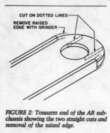
FIGURE 2: Tonearm end of the AR sub removal of the raised edge.
[…] inner platter. Wipe all the old oil off the go. with a soft paper towel.
Set spindle aside so it will not get scratched or bent. Carefully remove the motor pulley. It is a snug fit, but if you pull straight up, it will come off easily. Set the pulley aside.
Now remove the T-shaped sub chassis. As you do this, a steel ball bearing will fall out of the tonearm well. Discard it. The flat, white nylon bearing at the bottom of the platter spindle well might also fall out (although the oil usually holds it in place). Do not lose it. Remove the three 10-24 nuts and lock washers that hold the subchassis in place and pull the subchassis off the top plate.
Set the subchassis aside, along with the three springs, rubber spring mounts and foam dampers.
Cut the four motor leads, leaving them as long as possible. Remove the screws that hold the motor in place.
Be careful not to drop the motor or hit the shaft against anything. Set the motor and its mounting screws aside.
(The screws should be 4-40 by 1/8 inch.) Remove the 0.022uF capacitor from the power switch and the 0.1uF capacitor that was connected to the motor, leaving the capacitor leads as long as possible. Set the capacitors aside. If you are disassembling the 115/230V universal turntable, you must also remove the 0.1uF capacitor from the small circuit board near the motor. You may discard the circuit board and its other parts (two caps and a switch). If you are building this turntable for 230V, 50Hz use, retain the circuit board and all its parts, carefully noting motor wiring. This article describes 115V AC, 60Hz wiring only. Remember that the smaller motor pulley is for 115V AC, 60Hz use.
Subchassis Preparation
Construction begins with preparation of the subchassis. Remove the three springs, along with the rubber spring mounts and foam dampers. These are cemented in place, but will come off easily. Clean off any excess cement and set the springs aside.
Next, remove the foam at the top of the platter bearing well with the blade of a small screwdriver, but be extremely careful not to scratch the sleeve. The purpose of the foam was to soak up any excess oil.
Unfortunately, with the foam in place, you have no way of knowing whether enough oil has been applied.
Be sure that no small pieces of foam are left to get into the bearing sleeve.
Fill the bearing sleeve about three fourths full of rubbing alcohol. This will dilute the old oil. Let it sit for a minute, then plug the hole with your thumb and shake. Dump the contents into a small can. The nylon bearing should fall out. Wipe it off with a clean, soft cloth and set it aside. Wipe out the inside of the bearing well. The best way to do this is to push a soft cloth down into the well and twist it around a few times.
After removing the cloth, cover the bearing well tightly so no debris may enter. You can do this by wrapping several layers of masking tape around the entire well.
Now remove the tonearm bearing well with a hole saw slightly larger than the tonearm well's outer diameter. Remove the raised edge from the subchassis, as shown in Fig. 2. You may do this most easily on a grinder.
Then make two straight cuts as shown, leaving a U-shaped slot where you will install the new tonearm base.
Now temporarily fasten a 4.5-by 2-inch piece of 16-gauge aluminum with two 0.75-inch by 10-24 bolts. The aluminum piece should be positioned on top of rs subchassis, as shown in Fig. 3. As you can see from the photograph, the left edge is placed against the triangular protrusion on top of the subchassis. Drill holes for the bolts approximately halfway be tween the spring hole and the left edge of the 16-gauge aluminum.
After you tighten the bolts, mark the center of the tonearm pivot hole.
For the Mayware Formula IV, Mark II and IM, this will be 209mm (8.5, inches) from the center of the bearing hole; for the new Mayware Mark IV, this distance will be 212mm (87 inches). The distance is 222mm (8.5 inches) for the Grace 707 and 747 arms. If you are in doubt, consult the data for the tonearm you intend to use.
The hole's diameter will be the same as the threaded portion of the arm base, which should be 7.5 inch for the Formula IV, Mark II. Check your arm base to make sure, as different versions of the Formula IV tonearm vary. Do not use the rubber mounting grommets supplied with the Formula IV (or any other tonearm).
These grommets will decouple the tonearm from the rest of the turntable. If the tonearm is tightly coupled to the subchassis, only one resonance point will exist for the arm, subchassis and platter. If more than one resonance point exists, as in a decoupled tonearm, relative movement between the stylus and platter will prevent the stylus from accurately retrieving all the information in the record groove.
Use another piece of 16-gauge aluminum, 2 by 1.5 inches, to make a large washer for the bottom of the tonearm base. In the center of this piece will be another hole the same diameter as the threaded part of the tonearm base. It will probably be easier to drill the hole in a larger piece of aluminum, then cut the piece down to 2 by 1.5 inches. You can see the position of this 'washer' in Fig. 4. You must also drill a hole in the 4.5-by-2-inch piece of aluminum above the spring hole, as seen in Fig. 3. After you have drilled all the holes in both pieces of aluminum, set them aside, along with the tonearm base and the hardware.
The balsa wood damping blocks come next. Cut 24 pieces of 0.75-inch balsa or bass wood three inches square. You will make eight pieces of three-layer plywood with these pieces. Glue the plywood together with Titebond glue. When you are making the plywood laminate, the grain of the inside pieces should be perpendicular to the outside pieces.
Dry the plywood blocks under moderate pressure--i.e., in a vise or with some weight on top. Titebond dries in two hours.
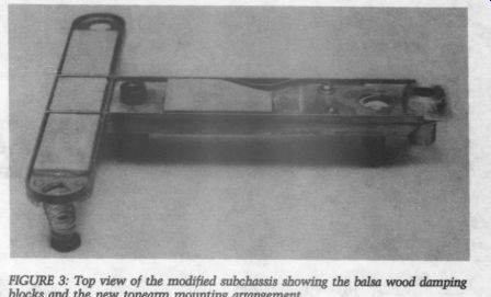
Figures 3 and 4 show the positions of the eight plywood blocks. Cut them to fit the spaces shown and
...damping blocks on...
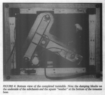
FIGURE 4: Bottom view of the completed turntable. Note the amping blocks
on the underside of the subchassis and the square “washer” at the bottom
of the tonearm base.
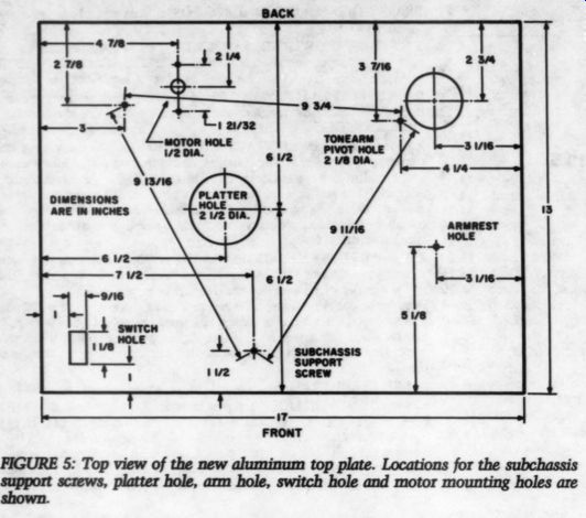
FIGURE 5: Top view of the new aluminum top plate. Locations for the subchassis
support screws, platter hole, arm hole, switch hole and motor mounting
holes are shown.
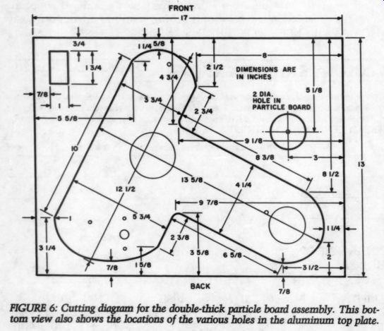
FIGURE 6: Cutting diagram for the double-thick particle board assembly.
This bottom view also shows the locations of the various holes in the aluminum
top plate.
...fasten them in place with five minute epoxy. Allow one hour for the epoxy to cure, as it will not reach a maximum strength in five minutes.
Now fasten the 16-gauge aluminum pieces and the tonearm mount.
Use the 10-24 bolts, flat washers, lock washers and nuts. If there is any play in the hole for the arm base, be sure the distance from the center of the bearing well to the center of the arm base is correct before tightening the large hex nut. You must also make sure that the two set screws in the arm base are positioned correctly. When the table is assembled as in Fig. 4, the Allen screw should face the rear of the turntable, and the other set screw should face the side.
When everything is in position, tight en the large hex nut and the 10-24 nuts. Be sure they are very tight.
Finally, replace the springs. The Grace tonearms (and the newer May wares) are too heavy for the original springs. Use Merrill Spring Kit A, available from Underground Sound ( 2125 Central Ave., Memphis, TN 38104), as a replacement for the original AR springs, but retain the rubber inserts and foam dampers […] Be sure to remove the springs […] subchassis. Run a bead of five-minute epoxy around the base of the springs and set them in place on the sub chassis, allowing one hour to dry..
Top Plate Preparation
Figure 5 is a top view of the new aluminum top plate, which should be 12-gauge aluminum, 13 inches wide by 17 inches long. It must be flat and square. My local welding shop did not cut mine perfectly square, and the necessary filing was an inconvenience at best.
You can cut the two large holes (for the platter spindle and tonearm) with a hole saw on a drill press. The exact position of the tonearm pivot hole will depend on the tonearm used. The location given in Fig. 5 is correct for the Mayware tonearms.
For most other arms, you must move the hole closer to the corner of the top plate (i.e., farther away from the platter hole). You can determine the exact distance between the platter hole and the tonearm pivot hole by consulting the data for the arm you intend to use. As stated earlier, it will be 209 or 212 mm for the various Mayware arms and 222 mm for the Grace 707 and 747. The size of the armrest hole will be determined by the diameter of the threaded base of the Formula IV armrest (which may vary, depending on which version of the Formula IV you own). The Formula IV, Mark III and IV tonearms, as well as the Grace 707 and 747 arms, have the armrest built into the tonearm base, making this hole unnecessary.
The square hole for the power switch accommodates the Carling illuminated power switch used in Hafler power amps. These are available from any electronic parts house. Of course, you may cut this hole to accommodate any switch you choose.
The motor shaft hole is 0.5 inch in diameter. The screw holes will be two holes slightly smaller than the 4-40 screw and then tap the holes.
You can purchase a 4-40 tap and handle at any hardware store.
You must also drill three holes to accommodate the subchassis support bolts (3-inch by 10-24 flat head). Positioning of each hole is shown in Fig. 5. The on-center distances between the screws is important if the sub chassis is to hang properly. You should countersink these holes to recess the top of the flat-head screws just below the aluminum surface. Do not mount the support screws, motor and switch at this time.
Figure 6 shows the cutout diagram for the double layer of 3/4-inch particle board that will be fastened to the top plate, as shown in Fig. 4. Begin by gluing and screwing together two pieces of 0.75-inch particle board, 13 by 17 inches, making a 1.5-inch-thick piece. Allow two hours for the Titebond glue to dry. Use 1.5-inch by #8 flat-head screws, countersunk. Then make cutouts in the particle board assembly for the switch, subchassis, motor and tonearm rest (if needed).
Numerous dimensions are given in Fig. 6 to assist in positioning the large T-shaped cutout, which allows space for the subchassis and motor. The size of this cutout is not critical, but the motor and subchassis must have adequate clearance. You may draw the cutout shape on the particle board, then do the cutting with a saber saw.
Fasten the particle board assembly to the aluminum top plate with 1% inch by #8 flat-head screws and 24-hour epoxy. Use nine screws, eight of which you should place around the perimeter of the top plate/particle board assembly. The ninth goes between the tonearm rest hole and the platter hole. Exact positioning of the nine screws is not critical, but each screw should have at least 1 inch of particle board on all sides to ensure a firm “bite ” into the board.
Countersink the screws into the top plate so that the tops of the flat head screws are recessed just below the surface. When you are sure that everything fits properly and all the holes are in the correct locations, apply a layer of 24-hour epoxy to the particle board, set the top plate on the particle board and install the nine screws. The screws should be tight.
Wipe off any excess epoxy before it cures.
Now install the subchassis support bolts (3-inch by 10-24 flat head) with lock washers and nuts. Be sure they are tight. Cover all countersunk screw heads with five-minute epoxy, leaving slightly more than needed to fill the holes. After the five-minute epoxy has cured (allow two hours), sand it flush with medium-fine sand paper, leaving the screw holes invisible. Then brush the entire top plate with medium-fine sandpaper, which will make a smooth surface. You might also have to sand the platter and tonearm holes and any other rough spots in the assembly.
To facilitate arm-height adjustment on the Mayware tonearms, drill two holes through the particle board, beneath and parallel to the aluminum top plate. These holes will allow easy screwdriver and/or Allen wrench to access to the set screws in the tonearm base. Drill one hole from the rear of the assembly, toward the center of the arm hole in the top plate. Drill the second hole from the side of the assembly, again toward the center of the arm hole. Both holes should be:
inch in diameter and % inch beneath the surface. These holes are un necessary if you are using the Grace tonearms. Spray-paint the entire assembly, bottom and top, with semigloss black enamel. Apply several thin coats.
Hardwood Base Construction
I will not give exact dimensions here, as they will vary somewhat depending on the thickness of the hardwood.
Minimum recommended thickness is 0.75 inch (I used 7/8-inch oak). The depth of the base should be 3.5 inches to allow plenty of clearance for the subchassis and tonearm wiring.
Because the top plate assembly will ...
--------------------
MATERIALS LIST
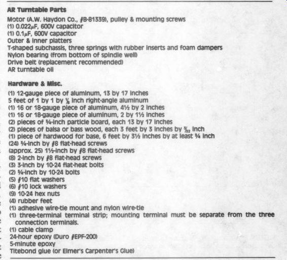
AR Turntable Parts
Motor (A.W. Haydon Co., #8-81339), pulley & mounting screws (1) 0.022F, 600V capacitor (1) 0.1xF, 600V capacitor Outer & inner platters T-shaped subchassis, three springs with rubber inserts and foam dampers Nylon bearing (from bottom of spindle well) Drive belt (replacement recommended) AR turntable oil Hardware & Misc.
(1) 12-gauge piece of aluminum, 13 by 17 inches 5 feet of 1 by 1 by % inch right-angle aluminum (1) 16 or 18-gauge piece of aluminum, 4% by 2 inches (1) 16 or 18-gauge piece of aluminum, 2 by 1% inches (2) pieces of %-inch particle board, each 13 by 17 inches (2) pieces of balsa or bass wood, each 3 feet by 3 inches by 3%, inch (1) piece of hardwood for base, 6 feet by 3% inches by at least % inch (24) %-Inch by #8 flat-head screws (approx. 25) 1%-inch by #8 flat-head screws (8 2-inch by #8 flat-head screws (3) 3-inch by 10-24 flat-heat bolts (2) %-inch by 10-24 bolts (5) #10 flat washers (6) #10 lock washers (9) 10-24 hex nuts (4) rubber feet (1) adhesive wire-tie mount and nylon wire-tie (1) three-terminal terminal strip; mounting terminal must be separate from the three connection terminals.
(1) cable clamp 24-hour epoxy (Duro §EPF-200) 5-minute epoxy Titebond glue (or Elmer's Carpenter's Glue)
-------------
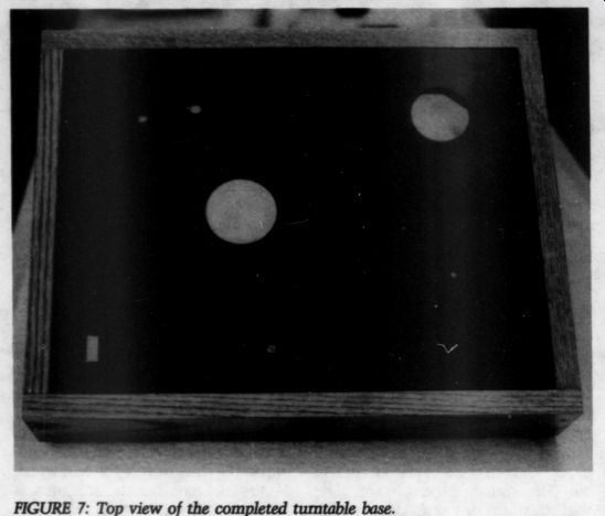
FIGURE 7: Top view of the completed turntable base.
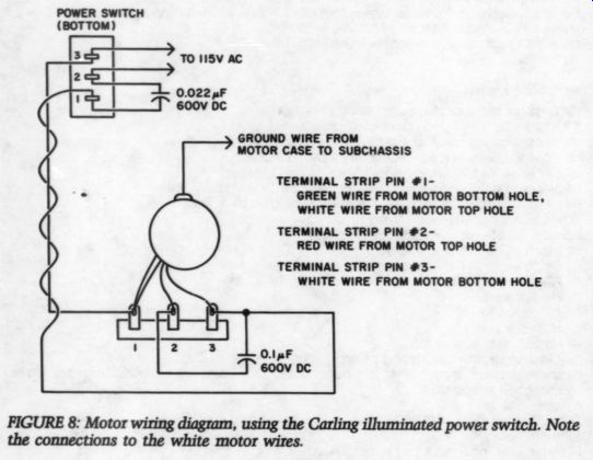
Fig 8. GROUND WIRE FROM MOTOR CASE TO SUBCHASSIS TERMINAL STRIP PIN #1
GREEN WIRE FROM MOTOR BOTTOM HOLE, WHITE WIRE FROM MOTOR TOP HOLE TERMINAL
STRIP PIN #2 RED WIRE FROM MOTOR TOP HOLE TERMINAL STRIP PIN #3 WHITE WIRE
FROM MOTOR BOTTOM HOLE.
... fit inside the hardwood base (as shown in Figs. 4 and 7), the inside dimensions of the base will be approximately 13 by 17 inches. This will normally require a custom fit, however, because of minor variations resulting from filing, sanding and finishing the top plate assembly. If you have already drilled holes in the top plate assembly to allow access to arm-height set screws, you should
drill two holes through the hardwood base.
A variety of finishes are possible for the hardwood base. I prefer a semi gloss polyurethane finish such as Zar, which also contains tung oil.
Fasten the top plate assembly to the inside of the hardwood base with four pieces of 1-inch, right-angle aluminum, as shown in Fig. 4. The right-angle pieces should be 1/8 inch thick. Exact length is not critical as long as the completed assembly resembles Fig. 4. You might have to notch the front aluminum piece as shown so that it does not interfere with the cutout in the particle board.
Use 24 3/4-inch by #8 pan-head screws (six for each aluminum piece). Be sure the top plate is flush with the top of the hardwood base before drilling pilot holes for the screws. Mount four rubber feet in the corners of the hardwood base, as shown. If screw fastened feet are not available, you can use adhesive feet, now carried by Radio Shack (No. 64-2342). This assembly, viewed from the top, should look like Fig. 7.
Motor Installation
Mount a three-terminal strip, using one of the screws holding the rear aluminum bracket, as shown in Fig. 4. Be sure the strip's mounting terminal is separate from its three connection terminals. Mount the motor with the original 4-40 machine screws. The motor wires should exit toward the rear of the turntable base (i.e., toward the three-terminal strip).
Connect a ground wire (using a spade connector) to the motor case, using the rear motor mounting screw. If the original 4-40 mounting screws are too short (or if the heads are too small), you can cut new 4-40 screws to size.
The ends of the 4-40 screws should not protrude beyond the surface of the top plate. Leave about 10 inches of ground wire; you will connect the other end to the subchassis later.
Figure 8 shows the motor and power switch wiring. I suggest that you make the connections to the power switch before you mount it in its hole. After mounting the power switch, complete the wiring as shown in Fig. 8. The wiring should be positioned as shown in Fig. 4. The two wires from the power switch to the terminal strip (which should be a twisted pair) should pass through a nylon cable clamp held in place by the middle screw used to fasten the aluminum bracket to the particle board.
At this point, plug in the line cord and turn on the switch. If the motor does not come on, you probably have the two white motor wires reversed.
Install the modified subchassis as shown in Fig. 4, using three 10-24 hex nuts, #10 flat washers and #10 lock washers. Be sure the bearing well is clean. Install a ground lug with another 10-24 hex nut as shown. Solder the ground wire from the motor case to this lug. Leave enough slack in the wire so that it will not interfere with the turntable's suspension.
Drop the nylon into the […] indentation faces up and the flat side rests against the bottom of the well.
Apply several drops of AR oil to the bearing well and to the spindle in the inner platter. (You may order extra bottles. of turntable oil ho Acoustic Research, 330 Turnpike Street, Can ton, MA 02021. ) Be sure the spindle is clean and insert it in the bearing well. You will probably have to add more oil. You have enough oil if you can see it bead up around the top of the well.
Gently push the motor pulley on to the motor. Be sure the pulley and inner platter rim are clean and free of grease and oil. Rubbing alcohol is an excellent cleaner, but don't get any on the rubber belt. Install a new AR belt around the inner platter and motor pulley (the smaller pulley is for 33.333 rpm). AR belts have a smooth side and a rougher side. The smooth side should come in contact with the pulley and inner platter.
Install the tonearm in its mounting hole according to the manufacturer's directions. Mount the cartridge and counterweight. The turntable should resemble Fig. 9.
Install the outer platter and the new platter mat. I recommend the Platter Matter, Music Mat or Audio quest mats, all available from HCM Audio ( 1600 Mangrove Ave., Suite B, Chico, CA 95926). Adjust the spring tension so that there is about 0.75 inch of clearance between the top plate and platter rim.
Now check the distance between the motor and the inner platter.
Carefully remove the outer platter and mat by pulling the assembly straight up, so the sub-chassis's relative position does not shift.
Measure the distance from the motor shaft to the edge of the inner platter.
It should be approximately 3/4 inch.
If the distance is too short, the motor pulley might hit the inner platter, and you must relocate the motor (an ...
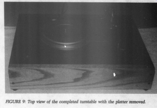
FIGURE 9: Top view of the completed turntable with the platter removed.
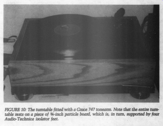
FIGURE 10: The turntable fitted with a Grace 747 tonearm. Note that the
entire turntable rests on a piece of 0.75-inch particle board, which is,
in turn, supported by four Audio-Technica isolator feet.
... admitted inconvenience). If you have followed the drilling locations in Fig.
5 carefully, however, you should have no problem. If everything is okay, reinstall the outer platter and mat.
Finishing Touches You can now complete the remainder of the arm and cartridge installation and alignment, again according to the manufacturer's instructions.
After inserting the tonearm cable into the base of the arm, tie the cable to an adhesive wire-tie mount (Radio Shack No. 278-441), as shown in Fig. 4. I recommend the location of the wire-tie mount shown in Fig. 4 only for extremely flexible tonearm cables.
A better location for most cables is next to the nylon clamp holding the switch wiring, on the opposite side of the turntable.
Leave plenty of slack in the arm cable so that it will not interfere with the turntable's suspension. Do not, however, allow the slack cable to touch any surface beneath the turntable, and be sure that this portion of the cable is not twisted. If the tonearm cable has a separate ground wire that connects to the turntable chassis (as the Mayware arms do), solder it to the ground lug on the sub chassis, as shown in Fig. 4. If not (which is the case with the Grace [… ] your preamp.
To level the turntable, first level the top plate, using a small, round bubble level (such as the Orbit Level, available in most hardware stores).
Technica insulator feet (discussed below) is also excellent. To level the platter, adjust the spring tensions slightly. You may also refine tonearm and cartridge adjustments. Be sure all set screws and mounting hardware are tight, and never use nylon cartridge mounting hardware.
The turntable is now ready to connect to your preamp. Be sure all ground wires are connected properly.
I advise against putting any type of cover over the bottom of the turntable. This creates a resonance cavity within the turntable base.
As you might already know, turn tables using a three-spring suspension are very sensitive to lateral vibration in the 0 to 10Hz region. This vibration is most frequently caused by a shaky platform or a floor that vibrates when someone walks on it. If you are plagued with an unsteady floor, the best solution is to mount a sturdy shelf on the wall to support the turn table. This will make the turntable virtually immune to floor vibrations.
As a less-effective alternative, I recommend using Audio-Technica AT-605 insulator feet. In my experience, the best way to use these is to set a piece of 0.75-inch particle board (same as turntable base) on top of the feet. Then place the turntable on top of this assembly, as shown in Fig. 10.
Figure 10 shows the turntable with the Grace 747 tonearm and Shure V15-IV cartridge. My current cartridge, however, is a Grace F9E/ Ruby. I use a dust cover (Fig. 11) manufactured by ADC for its 3001 cover is available from BSR (Parts Department, Route 303, Blauvelt, NY 10913). Contact BSR for avail ability and price information. I am sure a number of other dust covers will also fit this turntable. Do not hinge the dust cover to the base, as hinged covers are susceptible to air borne vibrations. You should, there fore, play your records with the cover removed.
In addition to the Merrill Spring Kit, Underground Sound also manufactures premium-quality replacement parts for AR turntables. These include a high-torque motor, platter antiresonance coating and new inner and outer platters. I have not used any of these myself, but I plan to try the high-torque motor in the near future. Contact Underground Sound for specific information and prices.
(Editor's Note: Also see the letter from Andy Catanzaro.)
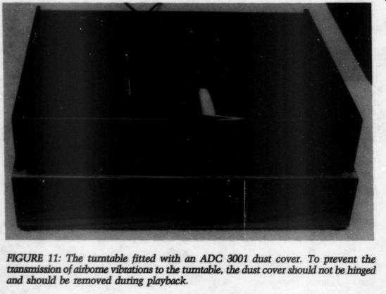
Fig. 11
Although it is not really appropriate for an author to 'review' his own design, I do want to say that this turntable is audibly superior to any conventional direct-drive turn table I have heard. It has more solid, well-defined bass reproduction than direct-drive designs and is free of the midrange and high-frequency harsh ness that plague many direct-drive turntables. I think builders will find that it compares quite favorably to many of the more expensive armless belt-drive turntables.
ACKNOWLEDGMENTS
I would like to thank Paul Steinberg of Potsdam, New York, for preparing the photographs for this article.
ABOUT THE AUTHOR: Mr. Galo is a recording engineer and electronics technician at the Crane School of Music, State University College of Arts and Science, Potsdam, New York, where he also teaches courses in sound recording and audio technology. For three summers, he has been on the faculty of the Saratoga-Potsdam Choral Institute. Mr. Galo has a B.M. in music education from the State University College at Potsdam. He is a member of the Audio Engineering Society, the College Music Society and the Association for Recorded Sound Collections.
REFERENCES
1. Benjamin, Andrew G., 'Turntables and Their Sound, Part I,’ Absolute Sound (Volume 7, Number 26), 1982, pp. 304-308.
2. Gloeckler, Fred M. Jr., 'Modifying the Formula 4 Tone Arm,' TAA 2/78, pp. 15-16.
3. Holt, J. Gordon, 'Formula 4 Tone Arm,’ Stereophile (Volume 4, Number 1), 1980, pp. 27-30.
4. Holt, J. Gordon, 'Replacing the AR ToneArm,’ Stereophile (Volume 4, Number 7), 1980, pp. 4-9.
5. Horan, John A., “Turntables,” Sensible Sound (Volume 3, Number 9), 1980, pp. 25-34.
6. Moncrieff, J. Peter, 'The Oracle Speaks,’ International Audio Review (Volume 5), pp. 3-15.
7. Moritko, Joseph, 'Modifying AR's Turntable for Other Tone Arms,' TAA 2/77, pp. 10, 11, 14.
8. Pfeffer, Arthur S., “The AR Turntable in Two Incarnations,” Absolute Sound (Volume 6, Number 24), 1981, pp. 492-494.
9. Spalding, John W., 'Adding Grace to AR, ” TAA 2/78, p. 36.
----
Also see:
Six-Transistor Ultra Low-Noise MC Phono Preamp
All-JFET MM/MC Phono Preamp, Part 1
Ultra-Low Distortion Phono Preamp: The LP-797
SAFETY FIRST-- and LAST, By Alan Watling