AMAZON multi-meters discounts AMAZON oscilloscope discounts
Although the inductor is one of the simplest of components as far as physical construction is concerned, its electrical behavior and proper ties may not be entirely obvious to the beginning student of electronics. Even among experienced technicians there may be some mystery as to how (1) a few turns of copper wire can have a current-limiting impedance of thousands of ohms, (2) voltage can appear across an inductor after it has been disconnected from the source, and (3) the voltage across the inductor can be greater than the source voltage. It is the purpose of this guide to examine the construction, characteristics, and applications of inductors and transformers, and to show that the "mysterious" proper ties of these components are easily understood consequences of a few basic principles.
In its basic form, the inductor is simply a coil of wire. The turns may be wound on a core of magnetic material to increase the inductance, or they may be wound on a non-magnetic coil form that serves no purpose except to provide mechanical support for the windings. If the coil has only a few turns, heavy-gauge wire can be used so that the turns will be self-supporting.
DEFINITION
Inductance is defined as that property of a component or circuit that opposes changes of electron low. It is this opposition to changing electron low that retards the build-up and decay of current through an inductor, causes the current to lag the applied voltage, and accounts for the fact that the impedance of the inductor is greater than its DC resistance.
The inductor opposes changes of current because such changes alter the intensity of the magnetic field. The changing field, in turn, cuts across the turns and induces a voltage of such polarity that it opposes the change that produced it. A sudden increase of current, for example, will generate a counter emf that opposes the supply voltage and therefore opposes the increase in current.
HISTORY
Inductance is an electromagnetic phenomenon. For this reason, the history of inductance is not entirely distinguishable from the history of electromagnetism. Although many experimenters have contributed to our understanding of electromagnetism in general and inductance in particular, three names st and out : Oersted, Faraday, and Henry.
Hans Christian Oersted, a Danish professor of physics, discovered that a magnetic force is produced by a current-carrying conductor. By observing the deflection of a compass needle, he proved that a circular magnetic field is established around the conductor.
In a sense, Professor Oersted and Michael Faraday crossed the same bridge, only in opposite directions. Oersted discovered that an electric current produces a magnetic field; Faraday discovered that magnetism can produce an electric current. Faraday, an English physicist, experimented with two coils of wire and discovered that current could be produced in one of the coils by either starting or stopping the current in the other coil.
Joseph Henry has been referred to as America's Faraday.
Faraday is credited with the discovery of mutual inductance, and Henry, with the discovery of self-inductance. In addition to his other experiments, Henry studied the spark discharge from a Leyden jar (an early form of the capacitor ) and discovered that the discharge was oscillatory rather than unidirectional. He laid the foundation for the development of radio communication by demonstrating that the discharge current through one wire could induce current in another wire at a distance.
CLASSIFICATION
Inductors can be classified in many ways: according to core material (air or iron), frequency (audio or radio), or application (power-supply filter, horizontal-linearity control, peaking coil, etc.). Classification can also be based on the Method of winding: single-layer, multi-layer, pancake, and pie sections.
The terms air core and iron core are employed in a very general sense. An " air-core" inductor, for example, employs a non magnetic core (not necessarily air; a tube or rod of ceramic or plastic may be used). Similarly, an "iron-core" coil may employ a magnetic material other than iron.
UNIT OF MEASUREMENT
The unit of measurement of inductance is the henry (in honor of Joseph Henry). A henry (h) is defined as the amount of inductance across which one volt will be induced when the current in it changes at a rate of one ampere per second. Expressed in another way, one henry is the amount of inductance that will have a reactance of 6280 ohms at a frequency of 1000 Hz*.
The millihenry (mh) and microhenry (uh) are subdivisions of the basic unit and are equal to a thousandt h and a millionth of a henry respectively. An inductance of 5 henrys is therefore equivalent to 5000 millihenrys or 5,000,000 microhenrys. Inductors commonly employed in electronic circuits range in value from the large "heavyweight " filter choke (t ypically 5 to 30 henrys) to the small peaking coils used in tv receivers (about 50 to 500 microhenrys).
* Hz (hertz) = cycles per second.
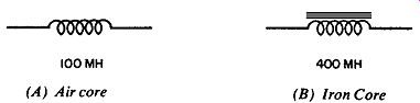
Fig. 1. The iron-core coil has more inductance than the air-core coil. (A) Air
core (B) Iron Core.
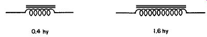
Fig. 2. Coil with twice as many turns has four times as much inductance.
FACTORS DETERMINING INDUCTANCE
What factors determine the inductance of a coil? What are the physical differences between a 5-henry and a 5-microhenry inductor? Inductance is determined primar ily by the number of turns and the type of core mat eial, and to a lesser extent by the diameter and spacing of the turns.
The effect of core material on inductance is illustrated in Fig. 1. The two coils shown are assumed to have the same number, size, and spacing of turns. As indicated, the coil with the iron core has a greater inductance than the one with an air core. In this example the permeability of the iron core is 400 (the coil with this core has 400 times as much inductance as the otherwise equivalent air-core coil).
Fig. 2 illustrates the relationship between inductance and the number of turns. The two coils shown are assumed to have identical cores and differ only with respect to the number of turns. For closely spaced turns, the inductance vaies approximately with the square of the number of turns. The inductor with twice as many turns therefore has four times as much inductance.
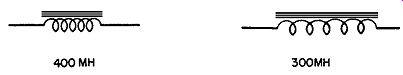
Fig. 3. Coil with closely spaced turns has greater inductance.
In Fig. 3 the coils are assumed to be identical in every respect except for the spacing of the turns. As shown, the one with closely spaced turns has greater inductance.