AMAZON multi-meters discounts AMAZON oscilloscope discounts
The characteristics of the inductor can be underst ood in terms of two basic concepts:
1. A magnetic field is established around a current-carrying conductor.
The magnetic lines of force encircle the conductor as shown in Fig. 1, and the direction of these lines can be determined by means of the left-hand rule: If the conductor is held in the lefthand with the thumb pointing in the direction of electron low, the fingers will be wrapped around the conductor in the same direction as the magnetic lines of force. If the conductor is wound in the form of a coil as shown in Fig. 2, the magnetic fields of the individual turns will combine to form a composite magnetic field. The composite field is such that one end of the coil is a north pole and the other end a sout h pole (like the field of a bar magnet). The direction of the magnetic field can be determined by means of another left-hand rule: If the coil is held in the left hand so that the fingers point in the direction of electron low, the thumb points to the end of the coil that is a north pole.
2. Voltage is induced in a conductor being cut by a magnetic field.
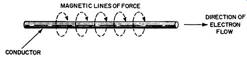
Fig. 1. Lilies of force encircle current-carrying conductor.
Fig. 2. Current-carrying coil generates a field like that of a bar magnet.
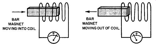
Fig. 3. Voltage is induced in coil cut by magnetic lines of force.
In Fig. 3, the turns of the coil are cut by the lines of force of the approaching magnet. As a result, voltage is induced in the coil, as indicated by delection of the meter pointer. If the magnet is now withdrawn from the coil, the turns will again be cut by the magnetic field, and voltage again induced in the coil. This voltage, however, is of opposite polarity to that induced when the magnet was moved into the coil. Voltage is induced in the coil only when there is relative motion of the field with respect to the coil. The effect is the same whether the magnet is moved and the coil is stationary, or the coil is moved and the magnet is stationary. If both the magnet and the coil are stationary, the turns are not cut by the magnetic field and no voltage is induced in the coil.
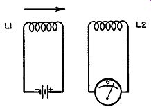
Fig. 4. Coil LI replaces bar magnet of Fig. 3.
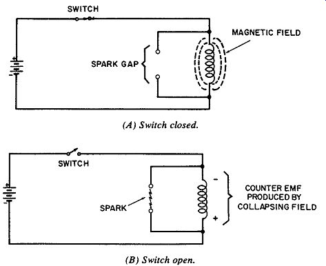
Fig. 5. Energy stored in magnetic field is returned to circuit when field
collapses. (A) Switch closed. (B) Switch open.
The bar magnet in Fig. 3 can be replaced by a current-carrying coil (Fig. 4). As before, motion of either coil with respect to the other will cause deflection of the meter. The need for mechanical motion can be eliminated by energizing coil L1 with alternating current rather than direct current. This produces an alternating magnetic field that cuts the turns of coil L2. Since the field itself is in motion (alternately expanding and contracting) mechanical motion of the coils is unnecessary. The reader may recognize this as the principle of transformer action.
ENERGY STORAGE
It is well known among technicians that a capacitor can store electrical energy. That an inductor can also store energy is less well known and perhaps less obvious. In the inductor, energy is stored in the magnetic field established by the current. This is illustrated in Fig. 5A. If the Switch is now opened as in Fig. 5B, the magnetic field will collapse and energy will be returned to the circuit. The collapsing field cuts across the turns and induces voltage in the coil. This voltage, the counter emf, produces a spark across the gap. The magnitude of the counter emf is determined by the intensity of the magnetic field, the rate at which it collapses, and the number of turns cut by the collapsing field. Because of the rapid collapse of the field in Fig. 5B, the voltage returned to the circuit is greater than the supply voltage.
This technique of increasing voltage is employed in various electronic devices. The high voltage required to ionize a fluorescent lamp, for example, is the counter emf induced in the inductor (ballast ) when the starter switch opens and allows the field to collapse. A similar technique, using the inductor as an autotransformer, is employed in the high-voltage circuit of the tv receiver. Automotive ignition systems employ the same principle. When the breaker points open, the collapsing field in the spark coil produces the high voltage for the spark-plug gap.
The amount of energy stored in the magnetic field of an inductor is specified in joules (a joule is equal to one watt-second): where, W is the stored energy in joules, I is the current in amperes, L is the inductance in henrys.
COUNTER EMF
When the current in an inductor changes, the magnetic field changes accordingly and cuts across the turns of the coil. In accordance with Lenz's law, the voltage induced in the coil by the changing magnetic field is of such polarity that it opposes the change of current. A decrease of current in the inductor, for ex ample, produces a counter emf that at tempts to increase the current. Conversely, an increase of current in the coil produces a counter emf that tends to limit the current. In a sense, the coil can be regarded as a current-regulator that at tempts to maintain the current at a constant value.
TIME CONSTANT
Although counter emf at tempts to prevent changes of current, it does not entirely succeed in doing this. It does, however, increase the length of time required for the current to change. This time constant of the inductor is determined by both the inductance and the resistance of the inductor. In Fig. 6A, the inductance is one henry and the resistance (including that of the coil) is 1000 ohms. With a 6-volt supply as shown, the final value of current will be:
I = E/R = 6ma
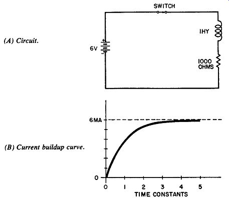
Fig. 6. When Switch is closed, current rises gradually toward final value
of 6 ma. (A) Circuit. (B) Current buildup curve.
When the Switch in this circuit is closed, however, the current cannot instantly rise to 6 ma. The buildup of current (Fig. 6B) is gradual rather than sudden because the increasing current produces an expanding magnetic field. The expanding field, in turn, induces a counter emf of opposite polarity with respect to the 6-volt supply. This opposing voltage effectively reduces the supply voltage and therefore limits the rate at which the current increases. As indicated in Fig. 6B, the current reaches its final value (approximately) after five time constants.
Numerically, the time constant is equal to the inductance divided by the resistance. The time constant of the circuit in Fig. 6A is therefore:
= 1 millisecond
SELF-INDUCTANCE AND MUTUAL INDUCTANCE
When the current in a coil changes in value, voltage is induced in this coil (self-inductance) as well as in any other nearby coil (mutual inductance). Two coils possess mutual inductance when the lux of each cuts the turns of the other. The value of mutual inductance therefore depends on the magnetic "closeness" of the coils. This closeness is referred to as the coefficient of coupling and is represented by the letter K. If all lux lines of each coil link the turns of the other coil, the coils are said to be completely coupled and the coefficient of coupling is specified as K = 1.
Since total coupling can exist only if the coils occupy the same space at the same time, practical values of K are always less than unit y.
The mutual inductance of two coils depends on their individual inductances and on the degree of coupling. Mathematically, mutual inductance is expressed by the formula:
__/ M = K __/L1 L2
…where,
M is the mutual inductance in henrys,
K is the coefficient of coupling,
L1 and L2 are the individual inductances of the two coils in henrys.
PARALLEL AND SERIES INDUCTORS
Coils connected in parallel have a total inductance less than the value of the smallest inductor. In this respect coils are similar to resistors in parallel, and a similar formula is employed. Assuming there is no coupling between the coils, the total inductance is:

---------
In practice, coils are rarely connected in parallel to obtain a smaller value of inductance. Cost, size, and weight considerations make it preferable to use a single inductor of the required value.
Coils connected in series are directly additive (if there is no coupling). Four henrys in series with three henrys will therefore produce a total of seven henrys. If the coils are magnetically coupled, however, the total inductance may be either more or less than the sum of the individual inductances-depending on whether the coils are connected aiding or opposing. If the coils are aiding, the total inductance is:
L, = L, + L2 + 2M
If the coils are opposing, the total inductance is:
Lt = L1 + L2 - 2M
… where, L1 and L2 are the individual inductances in henrys, M is the mutual inductance (also in henrys) and is equal to K __/L1 L2.
INDUCTIVE REACTANCE
Because inductance opposes changes of current, such changes lag the corresponding changes of supply voltage. If the DC input to an inductive circuit is suddenly changed in value, the current will not reach its new value until a inite length of time after the applied voltage has reached its new value. The same is true for an AC input voltage. In the case of a sine-wave input, for example, the current waveform will also be a sine wave but will lag the voltage sine wave. Each change of current lags the corresponding change of voltage. This is illustrated in Fig. 7; also shown is the waveform of the counter emf. Each time the current waveform reaches a peak (either positive or negative), for an inst ant the current is neither increasing nor decreasing-that is, the rate of change of the current is zero. Since the current is not changing, the counter emf at this inst ant is zero. It is for this reason that the counter emf waveform in Fig. 7 passes through zero at those inst ants when the current waveform is at its peak value.
The rate of change of current is most rapid when the current changes direction (passes through zero). At these instants, the counter emf is maximum.
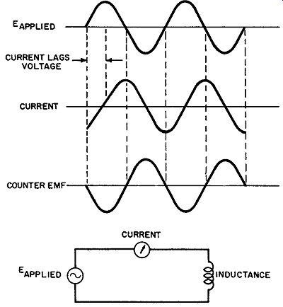
Fig. 7. Current lags voltage in inductive circuit.
As indicated in Fig. 7, the counter emf is 180° out of phase with the applied voltage. Since the counter emf "bucks" the applied voltage, current is limited to a smaller value than can be accounted for by the resistance of the coil. To the voltage source, the inductance therefore presents a high opposition to current. This apparent resistance of the coil is known as the inductive reactance.
Inductive reactance is specified in ohms and is symbolized by XL. Because the counter emf is larger if either the inductance or the rate of change of current is increased, the value of the inductive reactance depends on both the inductance of the coil and the frequency of the applied voltage. Numerically, inductive reactance is equal to:
X, = 2 pi fL
…where, X, is the inductive reactance in ohms, f is the frequency in hertz, L is the inductance in henrys, pi is a constant equal to 3.14.
A 1-henry inductance at a frequency of 1000 Hz will therefore have a reactance of:
XL = 2 pi fL = 2 x 3.14 x 1000 x 1 = 6280 ohms
The factor 2 pi r f is sometimes referred to as the angular velocity and is represented by a single symbol w (Greek letter omega).
The formula for inductive reactance can therefore be written:
X1 = wL
PHASE RELATIONSHIPS
In a purely inductive circuit (one with no resistance) as in Fig. 8A, the current lags the applied voltage by 90°. This is illustrated in Fig. 8B. Pure inductance can exist only in theory, however ; any practical inductor will exhibit some resistance.
For this reason, the actual angle by which the current lags will be less than the theoretical maximum of 90° (although the theoretical limit can be approached to within a small fraction of a degree). The phase angle between voltage and current is of ten rep resented by a vector diagram as in Fig. 8C. Because vectors are assumed to rotate counterclockwise. Fig. 8C indicates that current lags voltage.
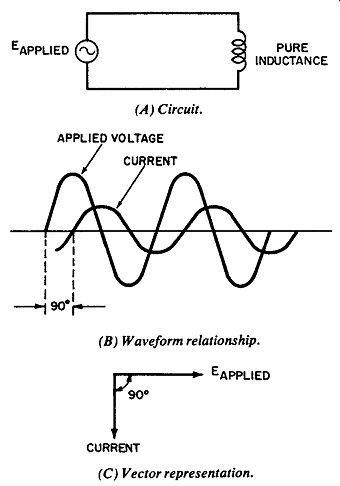
Fig. 8. Phase relationships in pure inductance. (A) Circuit. (B) Waveform
relationship. (C) Vector representation.
Since a purely inductive circuit has a phase angle of 90° and a purely resistive circuit has a phase angle of 0° (current in phase with voltage), a circuit containing both inductance and resistance will have a phase angle between 0° and 90°. An increase of resistance, either of the coil itself or any resistance connected in series with it, will therefore decrease the phase angle. For any given values of rand X,, the phase angle (6) can be determined from the relationship:
Example: By what angle does current lag applied voltage in a circuit having 3000 ohms of inductive reactance in series with 1000 ohms of resistance?
Solution:
X,
3000 tan 0=-r ==-- = 3 r1000
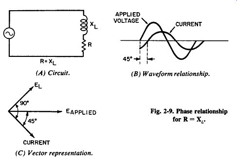
Fig. 9. Phase relationship for r= XL. (A) Circuit. (B) Waveform relationship.
(C) Vector representation.
Since the ratio of X_L to R expresses the tangent of the phase angle, the numerical value of this ratio must be looked up in a table of tangents. Reference to such a table indicates that a tangent of 3 corresponds to an angle of approximately 72°.
If the resistance of a circuit (Fig. 9A) is made equal to the inductive reactance, the tangent of the phase angle will be 1.
Reference to a table of tangents indicates that the phase angle is 45°, as illustrated in Fig. 9B. Note that the 45° angle is between current and applied voltage, not the voltage across the inductor. The voltage across the inductive component (Et ) is always 90° out of phase with the current, as shown in Fig. 9C.
Fig. 10 illustrates the relationship of the voltages in a circuit containing both inductance and resistance. Here the voltage drop across the resistor (ER) is assumed to be 30 volts, and the voltage across the inductor (E ) is assumed to be 40 volts. The applied voltage, however, is not 70 volts; voltages Es and EL are not directly additive because they are out of phase. These are alternating voltages, and the voltage across r is not 30 volts at the same inst ant the voltage across L is 40 volts. Since the voltage across r is in phase with the current, and the voltage across L leads the current by 90°,e and EL are 90° out of phase with each other. For this reason these two voltages must be added vectorially (a useful form for adding quantities at right angles to each other ):
E_applied = 50 volts
This can be compared to driving an automobile 30 miles north and then 40 miles east. At the end of the trip, the automobile is 50 miles (not 70) from its starting point.
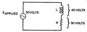
Fig. 10. Voltage relationships in circuit containing inductance and resistance.
IMPEDANCE
As shown in the preceding section, and EL must be added vectorially because they are out of phase. Likewise, the values of resistance and inductive reactance must be added vectorially to determine the total impedance of the circuit. A resistance of 80 ohms in series with a reactance of 60 ohms, for example, will not have an impedance of 140 ohms. Impedance Z is equal to the vector sum of rand X1:
Z= 100 ohms
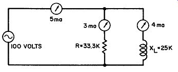
Fig. 11. R and X_L in parallel.
If the inductance and resistance are connected in parallel rather than in series, the total impedance will be smaller than either r or XL (similar to resistors in parallel). As shown in Fig. 11, the input voltage is applied across both rand X1 in parallel (the coil resistance is assumed to be so much smaller than the reactance that it can be disregarded). The inductor draws 4 ma of current (100 volts divided by 25K), and the resistor draws 3 ma (100 volts divided by 33.3K). The total current sup plied by the source is equal to the sum of these two branch currents. The currents, however, must be added vectorially because they are 90° out of phase with each other. The total current therefore is:
I_t = 5 ma
Since the 100-volt source supplies 5 ma of current, the total impedance (Zt) of the circuit is 20,000 ohms:
Z_t = 5 ma
LOSSES and Q
Pure inductance is only a theoretical concept; it can never be realized in practice. A practical inductor has resistance in addition to its inductance--the resistance of the wire with which it is wound. Current in the coil will therefore produce a power (PR) loss in the resistance of the conductor. For this reason a low resistance coil is preferable for most applications, and the suit ability of a given inductor for use in a particular circuit will depend on the resistance of the coil as well as the inductance. Two coils, for example, may have the same inductance but different resistances. The coil having the lesser resistance is of higher quality, or Q. This quality can be expressed as a numerical rating equal to the ratio of the inductive reactance to the resistance:
Q= X_L/R
Example: A coil in a certain circuit has 3000 ohms of reactance. If the resistance of the coil is 50 ohms, what is the value of Q?
Solution:
Q = 60
Q is a particularly important factor in communication equipment operated in crowded frequency bands. The selectivity of a receiver, for example, is determined by the Q of the coils in its tuning (tank) circuits.
The Q of a coil is also affected by the well-known skin effect. At high frequencies, current tends to circulate on the surface of a conductor rather than through the interior. This reduces the effective cross-sectional area of the conductor, and the high-frequency resistance of the coil is therefore greater than the value that would be indicated by an ohmmeter.
Litz wire is of ten utilized for coils designed for use in high frequency circuits. It is a conductor in which each strand is separately insulated. The combined surface area of these strands is greater than that of a single conductor of corresponding gauge (equivalent to the combined cross-sectional area of all the strands). Another means of compensating for skin effect is the use of hollow tubing instead of a solid conductor. Hollow tubing provides more surface area because it has two surfaces.
Another form of loss that has the same effect as increased coil resistance is loading. Assume that a second coil is placed near the first one for the purpose of coupling a signal. The additional coil is now the secondary of a transformer. If a load is connected across it, resistance will be reflected into the primary and will lower the Q of this coil.
Still another type of loss occurs in iron-core coils because the core behaves like a shorted single-turn secondary. As a result, the changing magnetic field produced by the coil induces eddy currents in the core material. An additional core loss, hysteresis, occurs at high frequencies because the core cannot reverse its magnetization as fast as the high-frequency current through the coil reverses polarity.