AMAZON multi-meters discounts AMAZON oscilloscope discounts
In digital counters and computers, information is represented and manipulated in binary numbers. The binary number system employs only two symbols (0 and 1) as compared to the familiar decimal system with its ten symbols: 0, 1, 2, 3, 4, 5,6,7,8 and 9.
Typical binary numbers therefore look like this: 110100001 and 1000010111.
The ones and zeros of the binary system can be represented by transist ors that are either conducting or nonconducting, by holes or no-holes at specified locations in a punched card, or by flux in either of two directions on a strip of magnetic tape.
Ferrite cores of ten are used to represent the ones and zeros of binary notation. A ring-shaped core (toroid) of magnetic material may be magnetized in either of two directions: clockwise or counterclockwise. One of these directions of magnetization can represent a binary one, and the other direction can represent a zero. The digits (bits) of a binary number can thus be represented by a group of magnetic cores, some magnetized in one direction and some in the other.
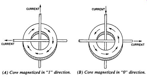
Fig. 1. Magnetic cores. (A) Core magnetized in "1" direction.
(B) Core magnetized in "0" direction.
As shown in Fig. 1, the direction of magnetization of a core depends on the direction of electron low in the wires passing through it. Actually, current is allowed to circulate for only a few millionths of a second; this is suf icient to magnetize the core.
The core then retains its magnetism in the same direction until current of opposite polarity in the wires reverses the magnetic flux. This ability of the core to magnetize quickly and to ret ain its magnetism indefinitely accounts for the use of thousands of cores in computer memories. The ferrite materials for this application are selected for their ability to ret ain magnetism and to reverse rapidly.
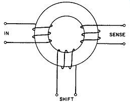
Fig. 2. Core Switching.
CORE SWITCHING
In addition to "remembering" binary data, ferrite cores are also useful for shifting dat a and for performing logical operations in the computer. A basic core arrangement is shown in Fig. 2.
If a pulse of current is passed through the "in" coil, the core will magnetize in the direction representing binary one. This process is referred to as setting the core or writing a one. If, at some later time, a pulse of current is passed through the "shift" coil, the core will magnetize in the direction representing binary zero. This process is referred to as clearing, reading or resetting the core.
Note that the "in" coil is used to put a one into the core, and the "shift" coil is used to clear the core to zero.
The "sense" coil produces output when the "shift" pulse reverses the magnetic flux of the core. This output is the voltage induced in the sense coil when it is cut by the reversing magnetic field. Note that an output may or may not appear in the sense coil at the time the shiftpulse is applied. This depends on the previous state (one or zero) of the core. If the core was already magnetized in the zero direction, the shiftpulse would produce no reversal of magnetic flux. Under these conditions, the sense coil would not be cut by lines of force and would produce no output voltage. The shiftoperation can therefore be regarded as an inter rogation of the core to determine whether it contains a one or a zero (in one case voltage will be induced in the sense coil, in the other case it will not ).
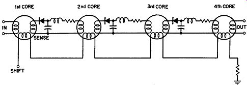
Fig. 3. Magnetic shift register.
THE SHIFT REGISTER
Fig. 3 shows a number of cores connected to form a shiftregister. Assume that the first core has previously received an in put pulse and is therefore magnetized in the one direction. If a shiftpulse is now applied, all cores will be Switched to the zero state (if they were not already in that state). As the first core switches from one to zero, voltage is induced in its sense coil.
The voltage charges a capacitor through a diode. After the shiftpulse is completed, the capacitor discharges through the input coil of the second core. The second core therefore magnetizes in the one direction. The binary one has thus been shifted from the first core to the second. If another shiftpulse is now applied, the one will move from the second core to the third. The diode connected in the output circuit of each core prevents the capacitor from discharging back through the sense winding of the same core. Discharge of the capacitor must therefore occur through the input coil of the following core. Shift-registers are useful for moving a long string of ones and zeros into or out of various computer circuits.
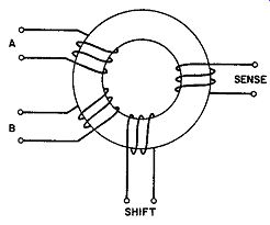
Fig. 4. Core with two input coils.
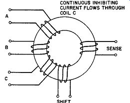
Fig. 5. Core with three input coils.
CORE LOGIC
Magnetic cores also are used to perform logical operations in computers and related equipment. Fig. 4 shows a core with two input coils labeled A and B. The core can therefore be set to the one state by applying a pulse to either coil A or coil B or both.
This corresponds to the logical operation "A OR B".
If current of opposite polarity is passed through coil B, it will cancel the effect of the current through coil A. Coil A is therefore inhibited and cannot wr ite a one into the core. The only way to set this core is to apply a pulse to A but not to B. This cor re sponds to the logical operation " A AND NOT B", a basic and important operation in computer logic circuits.
In Fig. 5, the core has three input coils. A continuous in hibiting current is passed through coil C. Both A and B must therefore be pulsed in order to overcome the inhibiting current and set the core to one. This corresponds to the logical operation " A AND B".
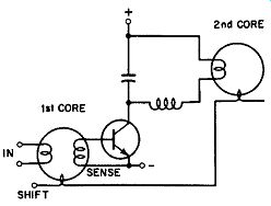
Fig. 6. Core-transist or shiftregister.
CORE TRANSISTOR LOGIC
For improved lexibility and reliabilit y, a transist or may be employed in conjunction with the core. As indicated in Fig. 6, the transist or receives its input from the sense winding. When a shiftpulse switches the core from the one to the zero st at e, the sense winding provides output voltage to "turn on" the transistor.
The transist or now conducts, and its current charges the capacitor. When the magnetic field of the core has inished reversing, no more voltage is induced in the sense coil. At this time, the transistor turns of fand the capacitor is free to discharge through the input coil of the next core. The capacitance and inductance provide suicient time delay to assure that the shiftpulse will be inished before the capacitor at tempts to set the following core.
This delay is necessary because a core cannot be set to the one state at the same time the shiftpulse is clearing it to the zero state.
High-speed switching of the core is desirable because it permits a greater amount of information to be processed in a given lengt h of time. The switching action of a magnetic core can be speeded up by employing a transist or in a regenerative feedback arrangement. A circuit of this type is shown in Fig. 7. Assume that a shiftpulse is applied, and the core begins to Switch from one to zero. Voltage is now induced in the sense coil, and the transist or conducts. Transist or current circulat es through the feedback winding and aids the shiftcoil in Switching the core to zero. As a result of this additional current through the feedback winding, the core reverses its magnetism very rapidly. As shown in Fig. 7, an undelayed output is available for the shiftwindings of other cores, and a delayed output is available for the inhibit or input coils.
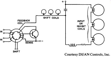
Fig. 7. Core-transist or logic. Coutesy DI/AN Controls, Inc.