AMAZON multi-meters discounts AMAZON oscilloscope discounts
Inductors and transformers are employed extensively in electronic equipment. A simple radio receiver, for example, has an antenna coil, an oscillator coil, two IF transformers, an audio output transformer, a power transformer, and a filter choke (which may be the field coil of the speaker). More elaborate receivers, such as those used in communications work, include more RF and IF stages and therefore require a greater number of transformers. Television receivers use an even larger number of these components. Industrial apparat us, telemet ering equipment, radar, navigational devices, and other electronic inst ruments also employ many inductors and transformers.
In general, inductors and transformers do not become defec tive as of ten as other components such as tubes and capacitors.
When a defect does occur, it is usually an open (broken wire) or a short (insulation breakdown). A coil may open because of excessive current or because chemical action (corrosion) has eat en away the copper wire. Other causes are thermal expansion of the coil form, or mechanical damage caused by careless handling.
Often, the break occurs at the solder terminal. In this event the coil can be easily repaired by cleaning the tip of the wire and re-soldering it to the terminal. Open coils can be easily located by checking for continuity with an ohmmeter. Shorted coils are more dificult to locate because only a few of the turns (or even a single turn) may be shorted. An ohmmeter will not reveal this defect because the shor tdoes not change the total resistance of the coil appreciably.
OHMMETER TESTS
The ohmmet er, used as a continuity checker, is useful for locating open coils. Depending on the associated circuitry, it may be necessary to disconnect one end of the coil from the circuit before making the measurement. A burned-out secondary winding in an audio-output transformer, for example, will still show a continuity reading because it is shunted by the voice coil of the speaker. Likewise, an open heater winding of a power transformer will show a continuity reading unless the tubes and pilot light are removed or one end of the winding is disconnected.
Manufacturer's schematics and service manuals frequently indicate the resistance of coils and transformer windings. When such information is available, the actual ohmmeter readings should be compared with these values. Even when such values are not available, an experienced technician will know the ap proximate ohmic values of various types of inductors and transformers. The windings of an IF transformer, for example, generally range from 5 to 20 ohms, a power-supply filter choke is typically 150 to 1500 ohms, and a power-transformer primary is usually about 10 ohms.
When an open coil is located, some thought should be given to the probable cause of this defect. An open caused by excessive current, for example, is distinguishable from an open caused by cor rosion or mechanical damage. A power transformer or filter choke that has been burned open by excessive current can be ident ified by the characteristic odor of overheated insulation.
If a bumed-out coil is replaced without adequate consideration of the probable cause, the new coil may bum out for the same reason as the original. An open filter choke or power transformer, for example, should not be replaced until the rectifier and filter capacitors have been checked for defects. Possible shorts in other circuits connected to the B supply should also be taken into con sideration.
In addition to checking the resistance of coils and transformer windings, the ohmmeter is also useful for checking leakage and shorts. A primary-to-secondary shor tin an interstage transformer, for example, allows the B voltage from one stage to reach the grid circuit of the following stage. A primary-to-core shor tin an interstage transformer causes the B voltage to be grounded through the core. This shor tincreases the current drain from the B supply, and may damage the filter choke, rectifier, or power transformer. Winding-to-winding shorts in a transformer are located by connecting the two ohmmeter leads to the two windings. The ohmmeter should show an extremely high reading -- corresponding to the resistance of the insulating material in the transformer. In a good transformer, this insulation resistance is many kilomegohms. If the transformer has more than two windings, similar tests should be made between all pairs of windings: primary to secondary 1, primary to secondary 2, secondary 1 to secondary 2, etc. In addition, each winding should be checked for possible shorts to the core. If one of the transformer leads is connected to ground (chassis), this lead should be disconnected before the transformer is checked for winding-to-core shorts.
All ohmmeter tests should, of course, be made with the power off.
Shorts between adjacent turns or adjacent layers are of ten dificult to detect with an ohmmeter because they produce only a small change in the total resistance of the winding. This does not imply that the short is not important if it involves only a few turns.
Even a single shor ted turn will prevent normal operation of the circuit and can cause excessive current. A shorted turn in the secondary of a power transformer, for example, can burn out the primary winding. Since a heavy current circulates through the shorted turn, and since this power must come from the primary circuit, primary current rises far above its normal value. Similarly, a shor tin the B-H circuit will of ten bum out the primary winding of the transformer.
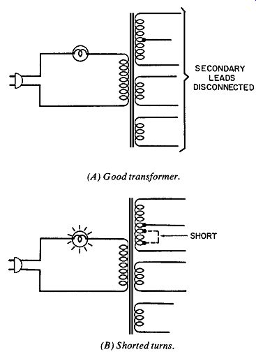
Fig. 1. Testing for shor ted turns. (A) Good transformer. (B) Shorted turns.
Turn-to-turn or layer-to-layer shor ts can sometimes be ident iied by the Method illustrated in Fig. 1. All secondary leads are disconnected, and a light bulb is wired in series with the primary.
If the transformer is not defective, only a small magnet izing current will circulate in the primary circuit--not enough to light the bulb (Fig. 1A). If the transformer has shor ted turns, however, the primary current will be high enough to light the lamp as shown in Fig. 1B.
VOLTMETER TESTS
Defective inductors and transformers often can be located with voltage checks. A power transformer, for example, can be tested simply by measuring the voltage across each winding. The voltage outputs of the two sections of a center-tapped secondary should be measured separat ely and compared. These voltages should be equal, or almost equal within manufacturing tolerances.
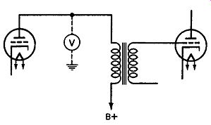
Fig. 2. Voltage test reveals defective coupling transformer.
Unbalance in the two halves may indicate shor ted turns, particularly if the transformer has been running hot ter than normal.
Voltage measurement is also useful for checking AF, RF, and IF transformers. The voltmeter used must be able to respond to these signal frequencies, or an appropriate probe must be used to conver tthe signal to a DC potential.
A voltmeter check for revealing a defective coupling transformer is illustrated in Fig. 2. Assuming the B supply voltage has been measured and found to be reasonable in value, the voltmeter is now connected to the plate side of the transformer primary. At this point, the voltmeter shows no reading. The transformer primary is therefore assumed to be either open, or grounded through a shor tt o the core. If the transformer appears to be overheating, this would lend credibility to the assumption that it is shorted. If the transformer is "cold," it can be assumed to be open. In either case, the results obtained by the ohmmeter will verify the assumption.
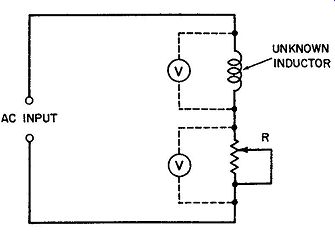
Fig. 3. Technique for determining value of unknown inductor.
A technique for measuring the value of an unknown inductance is illustrated in Fig. 3. The inductor and a Variable resistor are connected in series across an AC input. This input may be obtained from an audio generator or from the power line (avoid excessive current, which might overheat the inductor or resistor). The variable resistor is now adjusted until the voltage across it is equal to the voltage across the unknown inductor. The Function Switch of the voltmeter should, of course, be set to Alternating current. Two met ers are shown in Fig. 3, but only one is required. A single meter is, in fact, preferable because of possible differences in the calibration and accuracy of two separate meters. The meter is connected first across the inductor and then across the resistor which is adjusted to make these voltages equal.
If desired, an oscilloscope can be used instead of the meter, and the Variable resistor adjusted until the scope pattern across it is equal in height to the pat tern obtained across the inductor. When this balance is established, the value of the resistor is equal to the impedance of the inductor. The power is now turned of fand the resistor (leftat the same setting) is measured with an ohmmeter.
The resistance of the inductor is also measured with the ohm met er, and the unknown inductance can now be determined from:
VR2--r2 2 pi f where, L is the inductance in henrys, ris the measured value of the Variable resistor in ohms, ris the measured value of the coil resistance in ohms, f is the frequency of the AC input in hertz, tt is a constant equal to 3.14.
Examples: The Variable resistor in Fig. 3 is adjusted for a con dition of balance as described before. This Variable is now measured and found to be 2100 ohms. The resistance of the coil when also measured is found to be 150 ohms. If the frequency of the AC input is 60 Hz, what is the value of the unknown inductance?
Solution:
_VR2--r2 27f V21002- 1502 6.
28 X 60 5.5 henrys
Although this method does not yield laboratory accuracy, it is adequate for most applications and of fers the advantages of being quick and convenient to use. In addition, it requires no special equipment such as an inductance bridge.
RESONANCE METHOD
Fig. 4 illustrates a technique in which the unknown inductance is resonated with a known capacitance. The inductor and capacitor are connected as a parallel-resonant tank, and this tank is connected through a Variable resistor to a signal generator. In general, an AF generator is preferable to an RF generator, to mini-mize the effects of stray and distributed capacitance. An AC voltmeter (or an oscilloscope) is connected across the tank as shown.
SIGNAL GENERATOR KNOWN VALUE OF CAPACITANCE
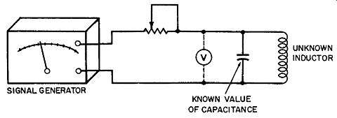
Fig. 4. Resonance Method of determining value of unknown inductor.
The Variable resistor and the signal generator are now adjusted so that the voltmeter pointer will swing sharply upscale as the gen erat or is tuned through the frequency to which the tank is resonant (the generator frequency that produces maximum delection of the voltmeter ). The unknown inductance can now be determined from:
where,
L is the inductance in henrys, fis the resonant frequency in kilohertz, C is the tank capacitance in microfarads.
Example: Maximum delection of the voltmeter in Fig. 4 occurs when the generator is set to 8 kHz. If the tank capacitance is.01 microfarad, what is the value of the unknown inductance? Solution:
A,neL L =-pc
=
Wxln = 64- =.0395 henry
INDUCTANCE BRIDGE
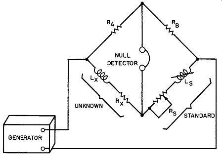
Fig. 5. Basic inductance bridge.
When high-accuracy measurement of an unknown inductance is required, an inductance bridge must be used. This is a laboratory-type instrument capable of much greater accuracy than can be at tained using the techniques illustrated in Figs. 3 and 4.
In the bridge circuit, the unknown inductance is compared against a known value of inductance called the standard. This standard inductance is Variable, as shown in the basic inductance bridge of Fig. 5.
An AC signal from the generator is applied to opposite terminals of the bridge. The frequency of this signal is commonly 60, 400, or 1000 Hz. A null detector, usually a headset or met er, is connected across the other terminals of the bridge circuit. The standard inductor (LA.) is now adjusted to balance the unknown inductor (L), and the standard resistor (Rs) is adjusted to balance the resistance (Rx) of the unknown inductor. When this balance has been established, the audio tone of the generator can no longer be heard in the headset. If a meter is used instead of the headset, the null or balance will be indicated by a zero reading of the meter. This occurs because the two terminals to which the null detector is connected are at the same potential when the bridge is balanced. The inductance and resistance of the unknown can now be determined from:
RX~ Rb
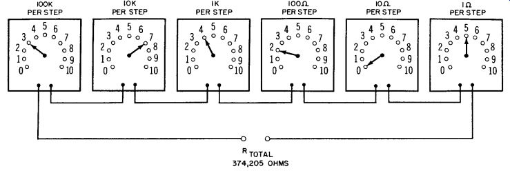
Fig. 6
Note that the standard and unknown inductors need not be equal in value when the bridge is balanced, but that the ratio of the unknown to the standard inductance be equal to the ratio of RA to RB. For this reason, a Switch may be provided in the in st rument to select one of several different resistors for use as R, (or RB). Its setting determines the range of inductance that can be measured. One Switch position, for example, may permit measurement in the microhenry range, another for the millihenry range, and still another position for the measurement of inductors of many henrys.
Calibrated dials generally are at tached to Variable standards Ls and Rs. When the bridge is balanced, these dials indicate the values of the unknowns, Lx and r. In most commercially available bridges, the Variable standards are called decades. A resistance decade, for example, consists of a Switch and several fixed resistors. According to the setting of the Switch, these fixed resistors can be connected in various combinations to produce different totals. Typically, six decades are used, and the resistance values are selected so that the total resistance can be changed in Steps of 1 ohm, 10 ohms, 100 ohms, IK, 10K, and 100K. A panel ar rangement for a six-decade resistance standard is shown in Fig. 6. With the Switches set as shown, the total re sistance is 374,205 ohms. Although each decade has eleven Switch positions (including 0), only four resistors per decade are required. The one-ohm-per-Step decade, for example, would have four resistors of 1, 2, 3, and 4 ohms. When the Switch is set to the 5 position, the 2- and 3-ohm resistors are connected in series; in the 7 position, the 3- and 4-ohm resistors are in series; in the 9 position, the 2-, 3-, and 4-ohm resistors are in series; etc. Similarly, the standard inductor (LA.) consists of fixed inductors and appropriate switching arrangements.
A headset is shown as the null detector in Fig. 5, but a meter is of ten used instead. To permit more accurate bridge balance, a high-gain amplifier is used with the null detector. As a result, even a slight unbalance of the bridge will produce an observable in dication on the null meter. The bridge can therefore be adjusted to near-perfect balance. Null amplifiers are sometimes designed to have a logar it hmic response. This prevents the null meter from being driven of fscale when the bridge is considerably of fbalance, but still provides high gain for small signals as the bridge is brought close to per fect balance. By the use of RC networks or LC tanks, the null amplifier is tuned to the frequency of the generator used to excite the bridge. The AC input is applied to the bridge, and the bridge output to the null amplifier, through shielded leads to minimize direct pickup from the generator to the amplifier.
OWEN BRIDGE
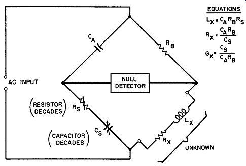
Fig. 7. The Owen bidge.
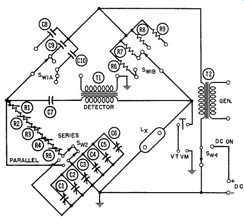
Fig. 8. Incremental inductance bridge.
Because low-tolerance inductance standards are expensive and dificult to manufacture, many inductance-measuring inst ruments employ a bridge that does not require a standard inductor. The Maxwell bridge, and also the Hay bridge, employ a capacitor as the standard. In the Owen bridge, shown in Fig. 7, the unknown inductor is balanced by a resistance decade (which can be more easily manufactured to a closer tolerance). A leading voltage (because of the lagging current ) appears across the unknown inductor in one side of the bridge. Because of the capacitance in the other side of the bridge, a leading voltage is produced across the standard resistor. For this reason, the resistance in one side of the bridge can be used to balance the inductance in the other side.
The resistance of the unknown inductor determines the phase angle of the leading voltage across this inductor. A variable capa citance determines the phase angle in the other side of the bridge and therefore balances the resistance of the inductor. The Switch dials of the standard resistance decades indicate the value of the unknown inductance. The Switch dials of the capacitor decades indicate the conductance (G) of the unknown. The resistance of the unknown inductor can be easily determined by:
The circuit diagram of an increment al inductance bridge is shown in Fig. 8. Switch SW1 selects the range of the bridge, to permit measurements up to 1111.1 henrys. Switch SW2 connects the resistor decades in either series or parallel with the capacitor decades (depending on the Q of the unknown inductor, sharper null balance may be achieved with either the series or parallel ar rangement of the standards). Switch SW3 permits con nection of an external vtvm to indicate the voltage across the un known inductor. When this switch is released, the vtvm is discon nected to prevent its input capacitance from unbalancing the bridge. Since the value of an iron-core inductor may vary ac cording to the DC current through it, it may be desirable to mea- sure the inductance at a particular value of current. A bridge that permits such measurement is known as an increment al inductance bridge. The instrument illustrated in Fig. 8 permits this type of measurement by means of SW4. Through this Switch, an external DC source can be connected in series with the input transformer from the AC generator. Capacitor C7 blocks the DC component from the output transformer that feeds into an external null-detector amplifier.
Another increment al inductance bridge is shown in Fig. 9.
It has full-scale ranges from 111 microhenrys to 1111 henrys, and can be balanced to a precision of 0.1 percent for an inductance as low as 0.1 microhenry. Full-scale conductance ranges are from 111 micro-mhos to 1111 mhos. The digits of the Switch dials are visible through windows in the front panel, providing in-line digit al readout of inductance and conductance.
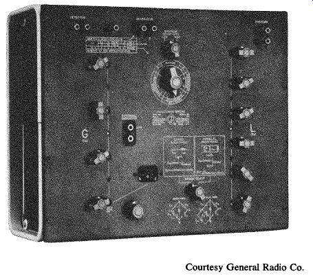
Fig. 9. Type 1632-A inductance bridge. Courtesy General Radio Co.