High-quality am/fm circuits can be found in the compact stereo component system, stereo receiver, AM/FM tuner-amplifier, or in a separate AM/FM/MPX tuner ( FIG. 1). The latest development is the digitally synthesized tuner with fully automatic tuning circuitry that offers precise reception. The automatic-tuning system automatically searches for receivable stations while a preset tuning system enters station frequencies into memory circuitry to provide one-touch, accurate tuning. In a direct- tuning system, push the number-input buttons to register a station frequency and the tuner will move directly to the input station. You might find all of these features in one deluxe AM/FM/MPX tuner chassis.
The digital and synthesizer tuner is controlled like the new TV chassis. The controller selects the station by supplying correct tuning voltage to the AM and FM varactor tuners ( FIG. 2). The controller has both manual pushbutton and random-search station-selection capability. Memory, latch, and LED display circuits are tied to the synthesizer controller.
Denon DRA-335R receiver
The Denon DRA-335R and DRA-435R receivers are quite similar except the 435R receiver has more functions, such as a second tape input for VCR, and a video in and out monitor. Also, the 435R has a separate bass-equalizer stage.
Both receivers have a digital tuning system controller, which tunes in the AM and FM stations ( FIG. 3). The input selector switches in the various audio-video modes. A microcomputer controls the digital controller, input selector, main volume, function indicator, function key switch, and speaker-protection system.
The DRA-435R receiver has power output of 55 W per channel, at 8 11, from 20 Hz to 20 kHz with no more than 0.05% total harmonic distortion. DRA-335R receiver has power output of 40 W per channel at 8 ohm.

FIG. 1 The Realistic Model STA-730 AM/FM/MPX stereo receiver with push-button
functions.
Remote control
Many of the new high-power receivers can be controlled with an infrared transmitter like the TV or VCR player. Besides being able to control the receivers, the same remote control unit can control a cassette deck and CD player. The full-system remote-control unit operates all major functions such as function switching, volume control, and preset station selection ( FIG. 4). The remote can be checked with an infrared indicator or with a nearby portable radio.
Digital synthesizer control
The PLL (phase-locked loop) frequency synthesizer provides electronic control of the AM/FM tuner. Both the AM and FM sections are controlled by signal voltage from the synthesizer control to the varactor tuner.
The FM system is a conventional tuner with varactor diodes in place of the mechanical capacitor with rotor and stator plates. This controlled voltage varies a local oscillator instead of the mechanical tuner. Buffer and prescaler stages are added so that the controller knows to what frequency the local oscillator is tuned. A stop signal is sent to the controller IC to tell the controller when a station is tuned in. When using the stop signal, the controller might stop when searching for a station. The audio is shut off with a muting circuit as it receives a muting signal from the controller when it’s in the searching mode.
The AM tuner is a conventional tuner but with varactor diodes replacing the mechanical tuner. A signal voltage from the controller selects the required station. The AM tuner and controller works in the very same manner as the FM system.

FIG. 2 Block diagram of Denon DRA-335R receiver tuning circuits.
Practically all controller features are performed by IC components. These large synthesizer processors have from 28 to 42 terminals. The controller also sends signals to the multiplexed drive display, showing the frequency of the tuned station on a multiplexed display. A signal is also sent to control the memory of the LEDs. Besides synthesized control, you might find analog frequency and quartz-locked tuning in the AMIFM tuner.

FIG. 3 The digital control tuning circuits of Denon DRA-335R receiver
system.
The varactor tuner The FM varactor tuner is tuned with several varactor diodes. A varactor diode will change capacitance when a different voltage is applied to it. By varying the voltage across the diode, a variable capacitor tunes the FM and AM bands like the TV tuner. In many of the early FM chassis, the tuning was controlled by a variable resistance control with a tuning knob. When the variable resistor was rotated, a different voltage was applied to the varactor diode, tuning in the various stations.
Along with the FM varactor tuner, you might find a varactor diode in the RF, nter, and oscillator stages ( FIG. 5). The same signal voltage is supplied by the controller. In some chassis there is a test point to measure the controlled voltage. The voltage applied to the varactor diode is a different voltage for each station.
Suspect a defective synthesizer processor if improper voltage or no voltage is found at the varactor diode. The controller or display might be defective if there is improper lighting of the various LEDs. Check the driver and memory circuits if there is no memory LED display. Critical voltage measurements at the processor or IC components should locate the problem. Replace all ICs, processors, and varactor diodes with components having the original part number.

FIG. 4 Remote control units are available with many of the newer receiver
control circuits. Remote Power; TAPE DECK SELECTOR buttons; FUNCTION SELECTOR
buttons; PRESET CHANNEL buttons

FIG. 5 All three FM RF, oscillator, and mixer stages are tuned with a
varactor tuner by a control voltage from the controller. In the earlier
receivers, the varactor tuners were controlled with a variable resistor.
FM FET radio-frequency amplifier Most FM receivers use an FET transistor in the varactor or conventional capacitor RF stage. Diode D3 is the varactor diode in the RF stage of the varactor tuner in FIG. 6. Here the tuning voltage applied to D3 is supplied through R4 (33 k-ohm) The FM coil (L4) is tuned by varactor diode D4. The same tuning voltage occurs at R7 from the same tuning-voltage source. TP1 is a test point to check the varying voltage supplied by the controller or pushbutton voltage selection.

FIG. 6 Varactor diode D3 tunes RF coil L2 with a variable voltage through
voltage-dropping resistor R4. Controlled voltage.
Conventional FET FM radio-frequency amplifier: A conventional AM/FMJ MPX block diagram is shown in FIG. 7. The conventional FM-RF amp is tuned by a mechanical tuner, VC101 ( FIG. 8). The tuned RF signal selected by VC101 is capacity coupled through C103 to the base terminal of the FET RF transistor. The secondary of L102 is tuned with another section of the mechanical tuner to the base of the mixer transistor, Q2 ( FIG. 9). Suspect a leaky or open FET RF’ transistor if you hear only a local FM station.

FIG. 7 The conventional AMIFM/MPX circuit might have two separate IC components.
The FM IF-AM converter circuits are contained in the first IC, and the second
IC operates the FM

FIG. 8 The mechanical tuner capacitor tunes in both AM and FM circuits
in the early conventional- tuner circuits.

FIG. 9 Mechanical tuner VC101 and VC102 select the desired FM stations
in a conventional FET FM RF circuit.
FM oscillator buffer varactor: The oscillator stages in the varactor tuner might consist of two or more transistors. The varactor diode selects the correct frequency in the oscillator circuit with voltage being controlled by the controller ( FIG. 10). Suspect a defective oscillator circuit if only a loud hissing noise can be heard, but no tunable stations can be heard. The same controlled voltage is found at the oscillator, mixer, and RF stages. Check for a variable voltage at point A when a different station is tuned in.

FIG. 10 The FM varactor oscillator circuit is tuned by D5 with a variable
voltage applied through R17 by a synthesizer controller or manual variable
resistor. Controlled voltage.
Conventional FM oscillator circuit --- The conventional oscillator transistor is coupled to a tuned coil and mechanical capacitor with the oscillator frequency coupled to the mixer stage ( FIG. 11). The incoming RF tuned station frequency and oscillator frequency results in a mixed signal at the mixer stage. Check the oscillator circuit if you can hear no tunable station. Critical transistor and voltage measurements will solve most oscillator-circuit problems. Erratic tuning might be caused by the oscillator plates touching the variable capacitor.
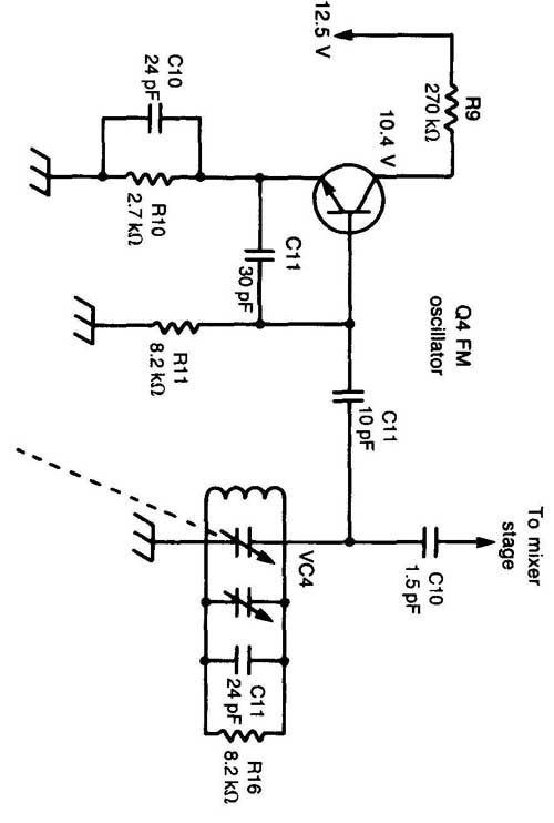
FIG. 11 Variable capacitor VC4 selects the FM oscillator frequency in
a conventional FM oscillator circuit. To mixer stage.
FM mixer circuits---The only difference between the conventional mixer and varactor circuits is the varactor diode coupled to the mixer transistor. Practically all mixer stages are conventional in operation with the 10.5 MHz IF frequency coupled to a ceramic IF network ( FIG. 12). In the early FM IF circuits, several transistors are found. A defective mixer stage might create a low hissing noise or a completely dead FM band if there is a leaky or open mixer transistor.
The AM varactor circuits You might find that the AM varactor tuner consists of a separate RF FET transistorized stage with a separate IC for the converter and IF circuits ( FIG. 13). A varactor tuning diode is found in the RF and converter stage. The same tuning voltage is fed to both tuning circuits. The IF output is fed to multiplex IC circuits. In large deluxe models, you might find entirely separate AM and FM circuits.

FIG. 12 Coil L1 in the base circuit of the FM mixer stage is tuned with
varactor tuner D4. The controlled voltage is applied through voltage-dropping
resistor R14 (33 k-ohm).

FIG. 13 Coils T101 and T102 are tuned by the same controlled voltage fed
to varactor diodes D10 and D11.
Conventional AM circuits---The AM antenna might feed directly into a separate RF transistor or IC component. In some chassis, one IC might control all the AM circuits. The AM output is then coupled to the audio switch circuits ( FIG. 14). Today, more and more IC components are found in the AM and FM control and tuning stages.

FIG. 14 The conventional AM circuits are tuned by a mechanical variable
capacitor with one IC serving for all AM functions in some AM/FM tuners.
FM IF circuits---Even the lower-priced receivers have one or two ceramic filter components in the IF circuits. You might find three in the large FM IF circuits ( FIG. 15). In the older circuits, you might find three or four separate IF transistorized stages with large IF transformers ( FIG. 16). The ceramic filter stages are simpler, easier to service, and cause fewer service problems than the older circuits.
You might find all of the AM/FM circuits on one board in compact receiver models ( FIG. 17). The small tuning capacitor, IF, and multiplex transformers are shown in the photograph. Here a combination of transistors and IC components forms the AM and FM circuits, while in the larger tuners the control tuner, AM/FM, and MPX circuits are found on separate boards.
FM multiplex circuits --- The IC component was first introduced in the audio and FM multiplex circuits. The input signal is taken from the last FM IF stage and fed to 1C3 ( FIG. 18). A 19 kHz adjustment is found at terminal 15. Separation adjustment is found at terminals 4 and 5. The stereo audio is taken from terminals 5 and 7 and fed to the selector-switch assembly. Pin 9 provides signal to the LED driver and tuning LEDs. Excessive whistling and poor sound separation might be caused by a defective MPX circuit. No stereo or only distorted sound might be caused by a defective multiplexer IC ( FIG. 19).

FIG. 15 Here three different ceramic filter components are used in the
FM IF circuits of transistor Q5. Many of the new tuners have IC components
in IF and matrix circuits.

FIG. 16 The IF transformer and matrix coils are found in the early receiver
circuits with transistorized stages.

FIG. 17 In this AM/FMIMPX receiver, all RF-IF and MPX components are mounted
on one board.

FIG. 18 A 19 kHz adjustment and separation adjustment controls are found
in the FM matrix circuits of 1C705. The left- and right-audio signals are
found at C81 and C82.
Denon DRA-335R/435R digital control system
The front-end tuner is controlled by a (F OUT) voltage from pin 11 of the digital tuning controller 1C603. The FM tuner front-end voltage is supplied at terminal (Vcc). The IF output signal couples to a ceramic filter network at the base terminal of TR602 ( FIG. 20). Another ceramic filter network is located between collector of TR602 and pin 1 of 1C601. 1C601 provides separate AM and FM signals to MPX 1C602. Both AM and FM audio signals are taken from pins 5 and 8 of 1C602.
The AM signal is picked up from the antenna connector and tuned at T601 with a varactor diode TC6O1. This AM signal is connected to pin 21 of 1C602. The AM IF transformer T604 is connected to output terminal 19 of 1C601 and goes through ceramic filter network CF605. The AM IF input signal appears at pin 17, and the output at pin 14 of 1C601. The amplified IF signal is capacity coupled to pin 1 of 1C602. Both the AM and FM signals are digitally controlled by 1C603.

FIG. 20 The IF output from the tuner couples to a ceramic filter to base
terminal of TR602 in a Denon DRA-435R/335R receiver circuits (courtesy of
Denon American Inc.).
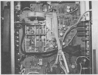
FIG. 19 One large PC board contains all AM/FMIMPX components in a Kenwood
KR-710 model.


FIG. 21 Radio Shack’s STAV-3100 RF and IF circuits with digital tuning
controller.
Radio Shack STAV-3 100 tuning control circuits
The FM tuner consists of an RF amp (Q138), mixer Q120, and oscillator Q119. All three stages are controlled with varactor diode tuning. The antenna coil is tuned with varactor diode (D120) with control voltage fed through R452 (33 k-ohm). RF coil A and B are tuned with varactor diodes D123B and D123C respectively. The oscillator circuit is tuned with varactor diode D124 with control voltage fed through R456 (33 k-ohm).
The IF signal is coupled to mixer (Q120) through T101 and ceramic filter CF1. Q121 provides IF amplification and fed to two ceramic filters CF2 and CF3. The IF signal is fed to pin 1 of IC 122. Inside IC 122 are 1st, 2nd, and 3rd IF amps, quadrature detector, level detectors, AFC (automatic frequency control) amp, audio mute control amp, meter drive, lever-mute drive, and audio-amp output.
The AM RJ antenna coil is tuned with varactor diode (D122-1/2) and fed to FET (field-effect transistor) RF amp (Q115). The AM oscillator coil is tuned with varactor diode (D122-1/2) with voltage through R371 (100 k-ohm). 1C120 provides buffer, oscillator, AGC (automatic gain control), AM detection, IF, and mixer circuits. The detector AM signal is found on pin 13 and fed through a resistor-capacitor network to the monaural MPX IC 123.
The power supply:
You might find many power-supply voltage sources in the FM/AM/MPX stereo synthesizer tuner. Extreme voltage regulation is needed for critical processor and digital circuitry ( FIG. 22). Simply isolate the defective circuit and check for adequate voltage. If the voltage is low or improper, trace the source back to the low-voltage power circuits.
FIG. 22 Several voltage sources are needed with the synthesizer and digital controlled low-voltage power supplies. 120Vac; ac; ac; To signal motors; To main digital circuits; To synthesizer circuits; To linear circuits; Low-voltage power circuits rectifiers and voltage regulators.
Although many of the receiver-tuner low-voltage circuits consist of nothing more than full-wave or bridge rectification, you might find several different voltage sources in the deluxe AM/FMIMPX stereo compact system ( FIG. 23). Here a 14.1 V source feeds the AM/FM/MPX circuits and equalizer amp with a 14.1 V source from the same bridge rectifier. Another bridge rectifier regulator circuit supplies a 17 V source to all audio circuits. Two separate half-wave diode rectifiers supply voltage to the phono motor and cassette deck motor.

FIG. 23 In the Denon DRA-435R1335R receiver circuits, several different
power sources feed the AM/FM/MPX circuits (Denon American Inc.).
Like most power-supply circuits, large filter capacitors (2200 uF) are used for critical regulation circuits. Check the regulator transistor for an open or leakage in the case of an improper voltage source. Most zener-diode regulators will increase or short when defective. Scope the 14 and 17 V sources for excessive hum in the audio circuits. In a dead chassis, look for an open fuse. Suspect a leaky bridge or diode rectifier if the fuse keeps blowing. Check for a shorted power transformer if the lights dim and the transformer hums without a fuse in the ac line.
Dead—no AM or FM---Check the power supply if there is a dead AMIFM/MPX tuner. Notice if the audio section is normal in the radio receiver. If the phono or cassette player is okay, suspect problems within the front-end circuits of the AM/FM tuner in a compact unit. Check the audio at the line output terminals of the tuner. Inject a 10.5 MHz IF signal at the mixer input terminal and notice if you can hear the signal in the speakers. If there is no audio, troubleshoot the IF and MPX circuits. Don’t forget to check for a dirty AM/FM switch assembly. Check for a broken AM/FM function switch.
The no AM/FM symptom was found in a Soundesign Model 69D. No voltage at the AIVIIFM selector switch indicated trouble in the low-voltage power supply. Zero voltage was measured on the emitter terminal of Q16 with 19.8 Vat the collector terminal ( FIG. 24). Q16 was found open with the transistor tester. Replacing Q16 with a universal

FIG. 24 Open regulator transistor (Q16) had zero voltage applied to the
FM and preamp circuits in a Soundesign Model 69D. Q16 was replaced with
an SK-3253 universal replacement. SK3253 transistor replacement solved the
no AM/FM symptom. To radio AF-FM and preamp circuits; Circled voltages occur
with open Q16.
No AM—FM good---Inspect the AM antenna coil for a broken core or wire connection. Test the AM converter transistor with the diode test of the DMM. Most universal transistor replacements will work nicely in the AM circuits. Measure all voltages at the AM transistor. Suspect a defective IC, even though the FM IF stages are supplied by the same IC component when the AM antenna coil feeds directly into the same IC.
Weak AM---Go directly to the AM antenna-coil assembly and RF transistor. Note if the antenna coil core is broken in two. Inspect all wiring connections from coil to the PC board circuits. Suspect the RF transistor if you can hear only a local station. The FET RF transistor in a Sanyo GXT300 component system was suspected because the AM section was dead ( FIG. 25). When voltage measurements were being taken on Q9, a local station could be heard. The D voltage should be 9.5 V but was only 1.2 V. Replacing the leaky FET (Q9) with a universal 2SK315 transistor solved the weak reception problem.

FIG. 25 Only the local AM station could be heard in a Sanyo Model GXT-300
receiver. FET Q9 was replaced with a 2SK315 transistor.
Weak or no AM can be caused by a poor connection on the AM detector in the AM IF stage. Sometimes these diodes will become leaky, producing distorted or no AM. A poor anode connection of D7 in a JC Penney 1322 model produced a dead AM symptom ( FIG. 26). Look for a leaky IC, which might include the AM converter, IF, and detector circuits. Suspect a defective AM converter if there are no tunable stations on the dial. A leaky capacitor in the AVC (automatic volume control) or AGC line to the RF or converter transistor might result in only one or two local stations being received.
Noisy AM---First, isolate the noisy sound to only the AM circuits. Determine if the noise is in the front end of the tuner or in the sound circuits by lowering the volume control. Transistors and IC components in the AIV1 and FM circuits might produce a low hissing noise. Short out the base and emitter terminals of each IF, oscillator, and mixer transistors to pinpoint the noisy stage. Actually, voltage and transistor tests won’t uncover a noisy IC or transistor. Replace the suspected IC when the input circuit is grounded out and noise still persists at the output terminal.
Both AM and FM quit after five minutes---Suspect something common to both AM and FM circuits when both channels are intermittent. Check the IF and matrix sections common to both AM and FM. Measure the voltage at the power supply and voltage regulator circuits. Monitor the voltage regulator and sound-output channels.

FIG. 26 A poor diode connection (D7) caused a dead AM symptom in a JC
Penney Model 1322 receiver.
Inject a 10.5 MHz signal into the IF stages and note if the sound comes through the speakers, or monitor each stage with the scope.
No FM—AM okay---Determine if a local station can be tuned in for a completely dead FM section. Measure the voltage ( FIG. 27) to the RF, oscillator, and mixer transistors. Suspect a defective voltage regulator circuit if you find improper voltage. A leaky RF FET transistor might cause a dead FM stage. Place a test probe on terminal D and see if local stations can be tuned in. Test the RF, oscillator, and mixer transistors in the circuit. Visually inspect the FM circuits for cracked or broken resistors. A poor board connection might cause the dead FM symptom.
Only a loud FM hiss could be heard in an RC-1248A stereo chassis. Voltages were way off in the FM circuits. Accurate voltage measurements were made on the voltage regulator, 1C202 ( FIG. 28). All voltages around the IC were higher than normal. Replacing the leaky 1C202 fixed the dead FM chassis.
Don’t overlook the multiplex stages when there is a dead FM symptom. Note if the stereo light, VU meter, or digital LEDs are working during FM operation. If the lights or LEDs indicate no signal, suspect a leaky MPX IC component. Take accurate voltage measurements on all IC terminals. Sometimes replacing the IC when an indicator light stays on is the only answer.
Weak FM—only local station---Go directly to the FM RF stage if there is only one tunable local FM station. Test the FET or transistor for leaky or open conditions. Inspect the chassis for lightning damage, especially if the chassis was connected to an outside FM antenna. Accurate voltage tests might indicate a leaky or shorted LED transistor. Check the first FM/AM IF transistor or IC component with a weak FM and no AM symptom. Very weak FM with frying noise might be caused by a leaky MPX IC component. Suspect the MPX IC if there is weak and distorted FM reception. A leaky MPX IC might run warm, but it should run cool in the FM circuits.

FIG. 28 Higher than normal voltages were found in an RCA RC-1248A chassis,
caused by a leaky low-voltage regulator IC.

FIG. 27 The VTVM or DMM is a required test instrument for servicing AMIFM/MPX
circuits.
Circled voltages occur with Leaky 1C202
No FM—very weak AM---In the JC Penney Model 2500, both the FM IF and AM IF circuitry are in 1C201. Because 1C201 is common to both bands, accurate voltages were made at each terminal. Voltages on pins 4, 8, 9, and 15 were quite low ( FIG. 29). Only 1.79 V was found at pin 4, which was the common voltage source from voltage regulator TR9O1. At first, TR901 was suspected of supplying low voltage to 1C201 (4.9 V). Actually, 1C201 was found to be leaky, causing the no FM and very weak AM problem.

FIG. 29 A no FM, very weak AM was found in a JC Penney Model 2500 receiver.
A leaky 1C201 was found with low voltage at pin4 (1.79 V).
Intermittent FM---Intermittent reception in either the AM or FM band is very difficult to locate. Try to isolate the intermittent reception to a given stage with accurate transistor and IC voltage measurements. Determine if the FM/AM switch is dirty. Clean all function switches with cleaning fluid. Spray inside the contact-point area. The intermittent FM problem might be found by applying pressure to components on the chassis with an insulated tool or pencil. Move the IF transformer to see if the FM music will cut in and out. Poor board connections around transistor and IC terminals might cause intermittent FM reception. Check for an intermittent transistor or IC which combines the first AM/FM IF amp stage. The intermittent matrix MPX IC might produce intermittent reception in either stereo channel.
Fading FM---A leaky FM oscillator transistor might cause the FM to fade out after several minutes of operation. Don’t overlook a varicap diode connected to the oscillator circuits. Check for a defective padder capacitor mounted on top of the FM tuning capacitor. Monitor the dc voltage applied to the FM circuits. Spray each transistor and IC with coolant after the FM station has faded away to locate a solid-state device. Suspect an AM/FM IF IC component when the FM fades out and only one AM station is heard.
FM hum and noise---Check for a leaky MPX IC or dirty preset control in the MPX circuits if the FM is garbled or microphonic. The FM padder capacitor on top of the main FM tuning capacitor might cause a tunable whistle or microphonic noise. A whistling noise on the low end of the FM band might be caused by improper FM alignment. Suspect a defective voltage regulator circuit if a tunable hum is found on both AM and FM bands. Intermittent FM hum might be caused by poor shield or grounds in the matrix circuits.
Stereo indicator lights on all the time---In many of the AM/FM stereo receivers, the FM stereo light will come on when an FM station is tuned in. lithe light does not come on, suspect a bad bulb, LED, or multiplex IC component. Sometimes the stereo indicator light will stay on all the time, indicating a leaky MPX IC. Take accurate voltage measurements of the MPX IC circuit, especially the terminal that connects to the stereo light. A leaky IC 102 (MPX) component caused the light to stay on all the time in a Sharp Model SA-5401 ( FIG. 30).

FIG. 30 A leaky PLL-Matrix IC 102 caused the stereo indicator light to
stay on all the time in a Sharp Model SA-5401 receiver. FM stereo light
on all the time.
FM tuning meter indicator---The FM tuning meter will operate in proportion to the input voltage of the antenna. Often, the meter circuit is tapped off the IC output signal and amplified by several transistors or IC circuits ( FIG. 31). The IF signal is then detected and applied to the meter amp transistor. The adjustment of the signal meter should be made at maximum with an FM signal generator.
AM/FM/MPX receiver alignment---Several years ago, regular AM and FM alignments were very easy. A touch up of the FM chassis might only take a few minutes. Today, with all the various types of receivers and circuits, many different test instruments are needed to do the job right ( FIG. 32). Each manufacturer’s alignment procedure should be followed to the manufacturer’s specifications. Always make FM alignments before trying a multiplex alignment. Besides AMIFM and MPX alignment, you might run into mute level, signal meter, separation, IF distortion, auto stop, and threshold alignment.
AM/FM alignment should never be attempted without the correct test equipment. Never simply touch up or turn various alignment screws or coil cores. If you don’t have the correct alignment test equipment, take it to someone who does. Most manufacturer service depots have the equipment and personnel for receiver alignment. Sometimes AM/FM/MPX alignment is only needed after replacing the IF transformer or multiplex coils, or when the receiver is not tracking properly.

FIG. 31 The FM tuning indicator takes signal from the IF circuits before
feeding to a meter amp transistor.

FIG. 32 Today, several different test instruments are required to completely
align the AM/FM/MPX tuner. Don’t attempt alignment without correct test
equipment.
AM/FM/MPX alignment procedures
For AM alignment, follow the AM alignment Table 5-1 with correct test equipment connected as shown in FIG. 33.
For FM alignment, follow the FMIMPX alignment procedure given in Table 2 with correct test equipment connected as shown in FIG. 34.
Twelve case histories
Although the following troubles cover a wide range of problems in the AM/FM tuner, many of them occur all the time in various tuner and receivers.

FIG. 33 Connect test equipment to test points (TP) and required test equipment.

Table 1. AM alignment chart with test points and test equipment.

Table 2. AM/FM/MPX alignment with correct test equipment and test points.
Tuning center & distortion
Repeat 1, 2, and 3 to obtain minimum distortion and same time indicating ± 50 mV on digital voltmeter.

FIG. 34 Connect test equipment to test points (TP) with FM/MPX required
test alignment.
No AM—normal FM---The AM band was dead with normal FM reception in a Sanyo DCR100 receiver. On checking the schematic, the AM and FM circuits were entirely separate. The AM RF FET transistor fed into IC2, which serves as converter, IF, and detector circuits of the AM section. Voltage measurements on all IC terminals were low ( FIG. 35). Because R51 was running quite warm, pin 11 was cut loose from IC2. Right away, the 14.8 V source returned to normal. Replacing IC2 (LA1240) restored the AM band.
No FM—normal AM--First voltage measurements were taken in the FM circuits of a Sharp Model SR 150. The voltage on each transistor was lower than normal. The 10 V source had dropped to 9.5 V. A quick transistor test of each transistor with the DMM indicated the RF-FET amp Q101 was leaky. Another voltage test on Q101 found 0.55 V on the S and G terminals ( FIG. 36). Local stations popped right in after replacing the leaky 2SK49H FET transistor.
Dead front end---The regular signal meter or the FM tuning-meter indicator showed no signs of movement in a Marantz Model 2252 tuner. A quick voltage measurement on the output transistors was normal (41.7 V), indicating the main power source was okay. However, the voltage source feeding the AM/FM circuits was only 6.4 V. The power supply voltage regulator (Q803) was found open. Replacing Q803 with a universal ECG152 replacement fixed the dead AM/FM section.

FIG. 35 A leaky AM converter, IF, and detector IC2 in a Sanyo DCR100 receiver
caused the no AM and normal FM symptom. Universal transistors and IC components
work fine in sections where original components are not available.
No AM or FM---No voltage was found within the AM or FM circuits of a Pioneer deluxe 1000TA tuner. Tracing the voltage source back to the power supply showed the voltage regulator (2S367) was leaky. The voltage regulator transistor was replaced with a SK3444 universal replacement.

FIG. 36 Leakage between terminals G and S of the FM transistor (Q101)
caused a no FM, normal AM reception in a Sharp Model SR15O. Very low voltage
on terminal D indicated a leaky RF transistor.
Fading FM---After a JC Penney Model 683-3233 receiver was on a few minutes, the FM reception would fade out and then emit only a low rushing noise. The AM section remained normal at all times. FM oscillator (Q103) was replaced with a 25C461C transistor ( FIG. 37). The varicap (1S2790W) D101 was replaced with a component having the original part number. When FM drifting was noticed in several of these same model receivers, both the varicap and Q103 were replaced at the same time.
To FM mixer; C121 15 pF

FIG. 37 Replace Q103 and D101 for fading or drifting FM in a JC Penney
Model 683-3233.
No FM—AM good---In a large compact AM/FM/MPX cassette Sharp SG143OA player the FM was dead with normal AM reception. The FM band had only a low hissing noise. Voltage test in the FM circuits indicated low collector voltage on FM oscillator (Q002). At first, Q002 was suspected of leakage with very low circled voltages ( FIG. 38). With further resistance tests (C102) was found leaky. Both C012 (0.01 uF) and R010 (100 ohm) were replaced to restore FM reception.
Rushing FM—AM okay---Only a low rushing noise could be heard on the FM bands, but the AM section seemed normal. The voltage measurements on the FM RF and FM converter transistors were about half the supply voltages (3.4 V). This same voltage was applied to the AM circuits, and AM stations could be heard over the entire dial ( FIG. 39). Both FM transistors tested normal. The voltage source from the voltage regulator amp was only 5.3 V and should be 9.5 V. Both Q104 and zener diode D103 tested good. Open resistor (R141) was found and replaced, returning the voltage source to 9.5 V.

FIG. 38 The no FM—AM good symptom in a Sharp SG143OA receiver was caused
by shorted C012. (0.01 uF) capacitor in the collector load terminal.
No FM—very weak AM Because the IF section is common to both the AM and FM circuits in a Panasonic SE-2250 receiver, voltages were checked at 1C201. The AN217 IC serves as both AM/FM IF amp and AM converter. The IC voltage source is fed from regulator TR9O1 (6.9 V). The voltage on source pin4 was quite low (2.57 V) ( FIG. 40). Replacing the leaky 1C201 with a universal SK3460 IC solved the AM and FM problems.

FIG. 39 Although the AM reception seemed normal with only a rushing noise
on the FM band, low voltage from the voltage regulator (Q1O4A) caused the
FM problem in a JC Penney Model 1721 receiver.
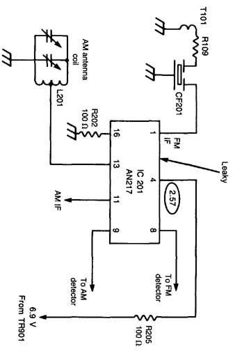
FIG. 40 The weak AM no FM symptom in a Panasonic Model SE-2250 receiver
was caused by a leaky AM converter AM/FM IF IC.
AM/FM distorted on right channel---Because the cassette player in a Sanyo M9975 receiver provided normal music, the IF and multiplex section was suspected of distortion in the right channel. Only 3.3 V was found at pin 6 of MPX 1C501 ( FIG. 41). At first, the AN7410 IC was suspected of being leaky, but a poor contact on the radio switch (SW715) turned out to be the culprit.
Microphonic squeal---Sometimes bumping the chassis in a JC Penney 3223 AMIFM/MPX stereo receiver would cause a microphonic sound in the speakers. Occasionally a loud squeal could be heard at certain points on the dial. The microphonic condition occurred only in the FM mode. When the large filter capacitor was tapped, the sound would begin. Replacing the padder capacitor CT3 in the oscillator section eliminated the microphonic noise ( FIG. 42).
No signal lights---None of the signal lights in a Soundesign M8090 receiver would light up. Although the receiver played perfectly, the LEDs were out. On checking the schematic, the driver IC feeding the LEDs were suspected until no voltage source was found at the IC terminal. The 15 V source was traced back to the power supply ( FIG. 43). Actually, a ground screw was loose on the chassis. The loose screw prevented the voltage return to the signal-light circuits.

Fig. 41: AM and FM distortions were found in the right channel of a Sanyo Model
M9975 receiver; the problem was caused by a poor radio switch connection.
To FM mixer

FIG. 42 A defective padder capacitor in the tuning circuit of a JC Penney
Model 3223 caused microphonic reception on the FM band. Replace CT3 to solve
the oscillating microphonic sound.

FIG. 43 A loose ground screw in the low-voltage power supply produced
a no-light in a Soundesign Model M8090 receiver.
Ground screw loose:
No FM meter movement---The FM meter would not move with normal FM reception in a JC Penney 2079 modular tuner. The meter movement was checked with the ohmmeter scale of a VOM and indicated continuity. A closer view indicated that the meter hand was binding against the warped meter backing material. Instead of replacing the meter, the front plastic cover was removed and the meter hand raised up with the blade of a knife. Sometimes you might find the meter coil open or a broken wire terminal at the rear of the meter.
Ten do’s and don’ts:
1. Do try to replace all FM transistors with the original replacements. The terminal leads are the correct length and they work every time.
2. Don’t overlook a broken iron ferrite core inside the AM antenna coil for weak AM reception. Sometimes they are difficult to see until they are removed.
3. Don’t forget to first spray AM/FM and function switches with cleaning spray. Thorough cleanup might solve the dead or intermittent problem immediately.
4. Don’t overlook a defective voltage regulator transistor with the intermittent chassis. Some of these transistors might test normal in and out of the circuit. Replace them because they sometimes break down under load.
5. Do take signal-in and signal-out tests on IC components in the tuner circuits. Take accurate voltage and scope waveforms. Check all components tied to the IC before replacing the IC.
6. Don’t use a high-wattage soldering iron on matrix or IF IC components when replacing them.
7. Don’t turn any adjustment screws to improve the receiver reception; you might make it worse. Complete AM/FM/MPX alignment should be done with correct test equipment, following the manufacturer’s alignment procedures.
8. Don’t throw away open coils or IF transformers. Most winding connections break right where they connect to the terminal lug. Remove a half turn of coil and repair it.
9. Do replace the FM indicator light bulbs or LEDs with components having the original part number. Remember they are not just another light bulb.
10. Don’t forget to replace all shields and common grounds after replacing critical components on top of the chassis. It’s very easy to leave off those small shields underneath the PC board.
Table 3 lists some additional problems along with their possible causes and suggested troubleshooting procedures.
Table 3. AM/FM/MPX troubleshooting chart.
| [Symptom] | [Possible circuit] | [Check] |
|
|
|
Also see:
How, when, and where to make tests
Repairing the deluxe amplifier
===