The most common application for soldering is in the construction and repair of electronic equipment.
Equipment Recommendations
Soldering Irons:
All types of gas irons and rechargeable irons are suitable for work on electronic equipment. Electric soldering irons for electronic work should have a power of less than 25 watts.
Most circuit boards would tend to be assembled and repaired with a 15- or 18 -watt soldering iron.
With modern electronics it is essential that the iron has a very low leakage factor (check this with the retailer when buying). This is a measure of the quality and efficiency of the element's insulation to earth. There is a minimum legal requirement for this factor under the Consumer Protection Regulations, but if the soldering iron you have purchased only just complies with this level then it is my recommendation that this is inadequate for use with electronics. You should use a soldering iron with a leakage factor better flan 1uA tested at not less than 1500 volts hot. A cold test would not give a good enough result. If the manufacturer of your soldering iron does not quote these figures in his leaflet or instructions then please check first. At the same time it is advisable for the bit to be earthed.
With an unearthed tip it may be necessary to use an earthed wrist and work strap to avoid problems when soldering sensitive electronic components. Not all components are that sensitive, and apart from CMOS devices it is unlikely that the hobbyist will come up against components that are flat sensitive.
Whilst it is unlikely that the hobbyist will find them necessary or financially desirable, the solder station is available and would be used for most electronic assembly in the industrial environment. It is my opinion that these are unnecessary for the hobby user. It is also important that the iron be used at its full temperature (400°C), so a temperature control facility is not necessary. The hotter the iron (within reason), the quicker the joint will be made and the shorter the distance the heat will travel into the component.
As to bit size, a 3mm bit is very suitable for most soldering activities on printed circuit boards although for very fine integrated circuits you may be happier with a 1 to 1.5mm bit.
For larger areas of copper you will probably need a 4.5 or 6mm bit for satisfactory soldering.
Solder Types
The selection of solder for electronics is very important. It is essential that only solder containing inert flux is used. No other type of pre-fluxed solder is acceptable, especially where only thin tracks exist on the circuit board. Suitable solders are 60/40 or "Savbit".
I would recommend that 22 swg solder is thick enough for all electronic work. The use of a thicker gauge will only mean that more solder than necessary will be used, and there is a great chance that it will flow over circuit tracks that should not be joined together.
Flux
As mentioned already, only an inert flux should be used. If the work has been cleaned properly then it should not be necessary to use a flux in addition to pre-fluxed solder.
Remember, if you are unsure of the type of flux you are using then test it on a waste piece of circuit board first.
Solder Sucker
A solder sucker will be found to be very useful for repair work.
Small Pliers
These also will be found to be very useful, both for positioning components and for removing them from the board when making repairs. They will also help you to avoid the temptation to prise the component from the board with the soldering iron.
Small Side -Cutters
These will be essential for cutting off the excess component wires to prevent them touching other tracks.
Damp Sponge
This is essential for the regular wiping of the soldering iron bit to keep it clean.
Learning to Solder
Most people's first attempt at soldering with electronics will involve the use of stripboard. This is a very useful material and prevents the use of many wires to connect the components to each other. It comes in several different sizes and is easy to cut into the size- you require. I would suggest however that you do not cut it until you have successfully completed your circuit. There is nothing more frustrating than finding you have done most of the circuit but have insufficient room for the last few components. Like printed circuit boards, stripboard must be soldered correctly and carefully to prevent the bridging of two or more strips.
Before actually soldering components into the' board, it is a good idea to practice soldering wires to the end of the strips without bridging the tracks, in the following manner.
1. Tin the Wires to be Soldered (Figure 8.1)
The purpose of pre -tinning the wires is to enable the soldering iron to make the final joint without the need to apply additional solder. You will need to use a soldering iron bit of at least 3mm for this process. A 1mm or 1.5mm bit is too small and will only cause a dry joint. Proceed as follows:
(i) Remove the outer insulation from the wire; about 4mm will be enough.
(ii) Make sure that the soldering iron tip is properly tinned.
(iii) Apply the soldering iron bit to the wire.
(iv) Apply the solder to the wire (not to the soldering iron bit). This will enable you to see when the wire is hot enough to melt the solder properly. The solder will then be seen to flow smoothly over the wire. When sufficient solder has melted onto the wire (the wire should be fully covered by solder) remove the solder and the soldering iron and allow the wire to cool.
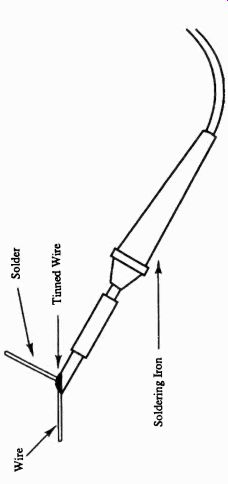
Fig. 8.1

Fig. 8.2 Tinning the board
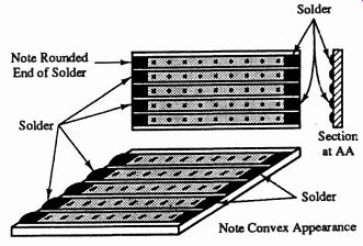
Fig. 8.3 Board after tinning
2. Tinning the Board (Figure 8.2)
Like the wire, the board will be easier to solder to if it has been pre-tinned. This unfortunately cannot be done when a component has to be inserted into the holes of the board, as pre -tinning will fill the holes and prevent insertion of the component.
Tinning the board, or even soldering to it, has to be done very carefully to prevent the solder flowing from one track to another. It will be a good idea to practice applying solder to the strips before going to the next stage. The size of soldering iron bit should not exceed the width of the copper on the track. Proceed as follows:
(i) Make sure that the soldering iron bit is fully tinned as previously described. For this operation ensure that the bit is not heavily loaded with excess solder.
(ii) Apply the soldering iron bit to the copper strip, and after a few seconds apply the solder to the strip. Do bit. Slant the bit away from the melting solder and finish applying the solder to the end of the strip and remove the soldering iron completely.
If you have been successful then the solder should be slightly humped, with a high point along the centre of the strip, and be shiny in appearance (Figure 8.3). If the solder is grey in colour then it may not have properly attached itself to the copper strip. If you have a magnifying glass available, look carefully at the strip and make sure that not even a whisker of solder has attached itself to one or other strip at either side (Figure 8.4). If it is clear then you have success fully tinned the strip.
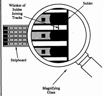
Fig. 8.4 Magnified view of solder bridging stripboard tracks
Now you can become more adventurous, and try to do the same to one of the adjacent strips. Follow the same procedure, taking great care to ensure that you do not melt the solder on the strip previously completed. If you do there is every chance that you will solder the two tracks together.
As mentioned before, the soldering iron bit used must not be wider than the board's track, otherwise it would then melt the solder over more than one track with the inevitable result of soldering those two tracks together.
When you have satisfactorily tinned several tracks, and inspected them, you can solder the wires to them that you prepared earlier. If all preparation work has been satisfactorily completed then no additional solder will be required for this stage. Proceed as follows:
(i) Check that the soldering iron bit is properly clean and tinned as before. If not then re -tin.
(ii) Hold the tinned part of the wire exactly parallel with the strip (Figure 8.5). It is very important that the wire is not at even the slightest angle as there is then the possibility of overlapping to the next track.
(iii) Place the soldering iron bit on to the wire (not the track) and watch the solder melt around the wire and then the track (Figure 8.6).
(iv) When the solder on the track has melted remove the soldering iron.
(v) This stage is the most important of all. It is vital that the wire is held completely still while the solder cools. Even if the wire is only moved slightly, it will cause a failed joint. Be patient and even if you think the solder has cooled, wait a bit longer. Moving the wire before the solder has cooled properly is the cause of many a dry joint.
Once again it will help you if you can inspect the joint through a magnifying glass to ensure that neither the solder nor the wire has strayed over to an adjoining track (Figure 8.7). Now try to attach more wires again being very careful not to touch adjoining tracks.

Fig. 8.5
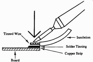
Fig. 8.6 Final position for soldering wire
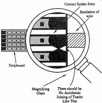
Fig. 8.7 Magnified view of completed joint
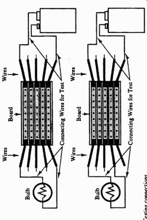
Fig. 8.8 Testing connections
If you now cut a small section off the main board, say about 2 inches along the strips, it will then be possible to solder wires to the other ends of the strips. This will enable you to test for bridged strips by using a battery and a bulb (Figure 8.8). To do this, attach the two outermost wires at one end to the battery and connect the wires from the other end of those strips to the bulb. The bulb should light. If it does not light then you may have a dry joint, so recheck your soldering. If it does, then move one of the battery connections to an adjacent wire and the bulb should not light. If it does, then the tracks are connected together and will need to be re-soldered. If the light does not light then congratulations, those two tracks have been successfully soldered. Before finally celebrating, check all the other tracks in the same way.
As can be seen, it is very easy to make silly mistakes by letting the solder flow from one track to the other as you are soldering. The more careful you are, the better chance you have of success.
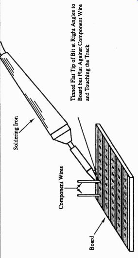
Fig. 8.9 Position of soldering iron for soldering components --- Tinned Flat
Tip of Bit at Right Angles to Board but Flat Against Component Wire and Touching
the Track
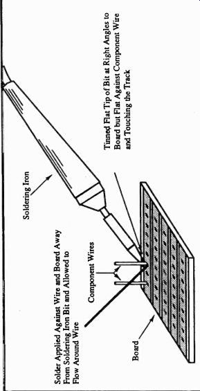
Fig. 8.10 Solder applied---Tinned Rat Tip of Bit at Right Angles to Board
but Flat Against Component Wire and Touching the Track; Solder Applied Against
Wire and Board Away From Soldering Iron Bit and Allowed to Flow Around Wire
Soldering Particular Components
As previously mentioned, the practice of pre -tinning cannot be applied to individual components. If you pre-tin the component it will not fit through the holes on the circuit board, and if you pre-tin the circuit board you will fill in the holes, preventing the components being put in. You therefore have to adopt a different procedure for soldering components to the board.
The procedure for most components will be the same with the exception of integrated circuits (chips), which I will deal with separately. The procedure will be the same, regardless of whether the board is a stripboard or a full printed circuit board. Firstly insert the component into the board, ensuring that the leads go through the correct holes and that it is the right way around. I shall explain how to overcome soldering in the wrong place in a later Section on desoldering. It is easier to get component placement right before commencing soldering than it is to correct it at a later date. It is best if several components are assembled at a time, especially if they are close to each other or adjacent on the same track. It is all too easy, when soldering one component lead, to fill an adjacent hole, making it impossible to insert a second component.
When several components have been inserted, you can proceed with soldering them to the board. It is my recommendation that you do not bend the component wires as it is possible that when you solder them they might allow the solder to spread over to the next track. Also, bending the component wires will make it very much more difficult to remove the component should it fail or be incorrectly inserted.
Apply the soldering iron bit to the side of the component lead, between the lead and the adjoining track (Figure 8.9).
Allow the component lead and the track to warm up for a second or two. Apply the fluxed solder to the area between the component wire and the track on the side away from the soldering iron bit (Figure 8.10). (If you have decided not to use fluxed solder, you should have applied an inert flux to the stripboard and the component with a fine paintbrush before starting to solder -- it sounds messy and it is.) Watch the solder melt and flow around the component leg and along the track, ensuring that the solder melts on both the track and the component lead. When a reasonable amount of solder (too much will only cause problems so apply it with care) is smoothly around the component lead and on the track, remove the soldering iron and allow the joint to cool.
This process should be very much shorter than the time it takes to explain. If you have successfully completed the joint, it should be shiny and form an oval mountain shape Long the track with its peak on the component lead (Figure 8.11). On a full printed circuit board that has been properly prepared for components, this "mountain" might be circular instead of oval. Finally trim the wires as close to the solder joint as possible with a small flat -backed pair of side cutters. It does not matter if a small amount of the peak of the solder is cat off with the wire. One word of warning. If you connect the power to your circuit before you have properly cut off all the excess wires and before you have carefully checked for bridged or dry joints, then it is more than possible that you will damage components.
The worst case I have seen was a gentleman who knew nothing about electronics or soldering but decided to buy a 10 -channel radio control transmitter and receiver kit by mail order. After many hours and many soldering mistakes which were eventually corrected (unfortunately for him not all), he decided to apply the power. One mistake he had not discovered was that the power leads were on the wrong way, so that when he applied the power all he got was smoke. He came to me to see what could be done, but I am afraid that my answer was to put it in the bin. He had no chance of finding the damage, which was probably extensive, and the cost would have been considerable had he employed an expert to repair it for him. The moral of the story is that you cannot check your joints and components enough times before applying the power. With many integrated circuits, electrolytic capacitors, transistors, etc., the wrong polarity can be fatal to the component, so take great care.
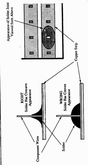
Fig. 8.11 Appearance of solder joint; Appearance of Solder Joint Viewed from
Above; Component Wires
Soldering Integrated Circuits
The simple answer to soldering integrated circuits (ICs) is don't unless it is unavoidable. Instead solder in an IC socket so that the IC itself can be plugged in later. This will save you a considerable number of problems at a later date should the IC need replacing. The procedure for soldering the socket is exactly the same as with the components, but obviously with so many leads in such a small space great care will have to be exercised to prevent bridging joints that should not be connected together. Some people prefer to use a smaller bit for ICs than other components, but remember that it is the size of the copper surrounding the joint rather than the size of the component that dictates the size of soldering iron bit to be used. Don't sacrifice the chance of a good joint for a smaller bit. Instead exercise more care to prevent the bridged joint.
Industrial Methods
Before leaving soldering and electronics, mention must be made of two modern methods of soldering which are used mainly in industry.
Flow Soldering: This is a production-line soldering system where all the components are inserted into the board, after which a conveyer system suspends the whole board over the solder bath; usually the heated solder is flowing across the bath. If the unit is correctly set then all joints will be properly soldered without the need for a soldering iron. The board is then passed over a cutting machine which trims the component wires to the correct length.
Unfortunately, even though extensive tests are applied after the boards have been soldered this system is prone to dry joints. Because of the widespread use of this system, the majority of faults in manufactured equipment are either dry joints or have been caused by dry joints. Hence the first thing to be done when repairing a failed circuit board is to go over the area of the fault with a soldering iron to remake the joints. It is surprising how many faults can be corrected in this way.
Soldering and Surface Mount Technology: Surface-mount technology is the latest system of printed circuit assembly used by industry. As the name suggests, the components are soldered onto the same side of the board as the printed track rather than the opposite side. This means that there are no wires on the components, but obviously this is not a practical system for the hobby user. In most cases very expensive and special tools and equipment have to be used.
Solder Pots
The solder pot is a very useful piece of equipment, especially if you have to tin many components or wires. The method of use is very simple and quick. The component or wire is dipped into a small pot of inert flux, after which it is dipped into the heated solder pot. After a short time the component or wire can be removed from the solder pot fully tinned.