When PS Audio changed hands a couple of years ago, one of the goals of the
new regime was to develop a D/A converter that was among the finest in the
world. Since the company was one of the first to offer a separate D/A converter,
the new owners asked, what could be more fitting than to come up with a real
killer D/A that’s still affordable? The UltraLink is the result of that effort.
The UltraLink D/A converter is certainly a breakthrough product in that it is probably the lowest priced unit to use a version of UltraAnalog’s highly regarded D/A converter module. A number of other features and design attributes also contribute to its overall excellence. Among these are the use of three isolated power supplies (for left and right analog outputs and the digital logic), 38,000 uF worth of Panasonic HFQ series low-impedance electrolytic capacitors, some 50 Mylar bypass capacitors that were chosen for their sonic benefits, a frequency-dependent negative-resistance (FDNR) third-order analog reconstruction filter, an unusual op-amp/discrete analog output stage, and the superior sounding NPC SM5803 eight-times oversampling filter between the input receiver chip and the D/A converter module.
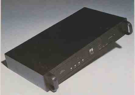
Front-panel control is exclusively through touch buttons that are located in a group, to the left of PS Audio’s logo. Starting from the left, these buttons handle power, polarity inversion, “Optical” input selection, and selection of the coaxial in puts. Indicator LEDs above the last three buttons show operating status. To the right of the company’s logo is another group of LED indicators for the sampling frequency in use, the presence of a locked-in data stream, and whether the de-emphasis and power are on. The UltraLink is always powered when plugged in and is designed to stay powered for best sound. When the power button is not pushed, the LED pilot light is out and the outputs are muted, but otherwise the system is on and ready.
= = = =
SPECS:
- Frequency Response: 20 Hz to 20 kHz, ± 0.3 dB.
- De-Emphasis Accuracy: ± 0.1 dB.
- Dynamic Range: 98 dB.
- Noise: —110 dB.
- THD: —94 dB with 600-ohm load.
- Crosstalk: —120 dB at 1 kHz.
- Dimensions 17 in W x 2 1/2 in H x 9 in. D (43.2 cm X 6.4 cm X 22.3 cm).
- Weight: 11½ lbs. (5.2 kg).
- Price $1 995 with AT&T optical connector, $2,195.
- Company Address PO Box 1119 Grover Beach, Cal. 93483.
= = = =
On the rear panel, from left to right, we have an IEC a.c. input connector, Toslink (and, optionally, AT&T) optical inputs, two coaxial inputs, a coaxial digital output, plus XLR and RCA analog output connectors for the left and right channels.
Inside the UltraLink is the most beautiful p.c. board ever to come out of PS Audio. This board is 0.093 inch thick, for structural integrity, and has been designed for minimum signal crosstalk. Populating this board are carefully chosen, high-quality parts. Build quality is excellent in this unit, and long and trouble-free performance would be expected.
Circuit Description:
Starting with the coaxial inputs, the signals from both terminals of the input connector are applied through coupling capacitors to the inputs of a differential line receiver. This receiver has hysteresis for increased noise immunity. The outputs of the coaxial input receivers, along with the outputs of the optical in put modules, are coupled to a signal selector multiplexer (MUX). The selected signal source is passed through a buffer chip and an out put coupling capacitor into a voltage divider. This produces the proper output level and impedance for an SPDIF digital output. (Such an output attenuator, to produce a proper SPDIF interface output, is not in most of the digital output circuits I’ve seen.) The selected output of the MUX also goes through a line driver/buffer into the primary of a signal-isolation transformer for the main data path. Control of the MUX for signal selection is through opto-isolators, to maintain the isolation of the digital front-end from the following circuitry.
Output from the secondary of the front-end isolation transformer is squared up by a Schmitt- trigger chip and passed on into the data input of the Yamaha YM3623B input receiver. (This chip also reads the sampling rate info from byte 3 of the SPDIF digital signal input protocol. The information is then applied, via a two-to-four decoder, to the sampling frequency LEDs on the front panel.) The relatively well-known trick of killing the crystal oscillator when signal lock has been accomplished for reduced jitter is used here, with a twist: One side of the crystal is pulled low actively, with a transistor. Master-clock, bit-clock, and left/right selection signals are passed on to the input of the NPC SM5803 eight-time upsampling digital low-pass filter. Data output of the receiver goes into one input of an exclusive-or (XOR) gate, the output of which goes to the data input of the SM5803. A logic level of 0 or 5V into the other input of the XOR controls the polarity of the data signal, and hence the final audio output polarity.
The SM5803 is a somewhat different animal than the more commonly used SM5813. It has digital de-emphasis, a digital attenuator, selectable noise shaping, and a soft-muting circuit. An arrangement of a four-bit binary counter and three MUXs is associated with a power-on reset circuit that sets up the mode register of the SM5803 chip.
The upsampled signals out of the SM5803 are passed into the UltraAnalog D/A module. Trimpots allow adjustment of the d.c. offset in the output from each channel of the D/A module—and hence the final analog output, as the following signal circuitry is direct-coupled.
Passing on to the audio output circuitry: D/A analog outputs are applied to a novel third-order low-pass filter, of the FDNR variety, that is said to be “out of the signal path” and which has been used in a few other CD players whose manufacturers made the same claim. If one defines shunt filter elements as being out of the signal path, I guess this circuit qualifies. I person ally do not agree that shunt circuit elements are out of the signal path, however. An interesting transformation of a classic LC filter yields the topology of the FDNR (Fig. 1). Output of the filter is passed into the final analog amplifier. This circuit consists of a unity-gain follower circuit made up of a carefully chosen IC driving a proprietary discrete buffer circuit. The negative output polarity for balanced outputs is generated by another circuit, as just de scribed, acting as a unity-gain inverter fed from the positive polarity output.
Front-panel touch control, LED indication of system state, and system-control logic take up a whole page of the Ultra- Link’s six-page set of schematics. Most of the control circuitry is rather straightforward combinational logic and flip- flops. The touch-button circuitry works as follows: The button picks up 60-Hz hum from your finger and applies the hum to the input of an op-amp that’s operated in an open loop (i.e., without feedback). There are four such circuits. The amplified outputs of the op-amps are rectified into a d.c. voltage to represent a logic “1” when a button is touched and a logic “0” when a button is not touched. These d.c. outputs of the touch-button circuits are applied as logic inputs to the signal-selection and control circuitry. Other logic in puts include emphasis-present and data-lock signals from the receiver chip, and system reset.
The power-supply circuitry starts out with two separate power transformers, one for the positive and negative analog supplies and the other for two digital supplies. The secondary windings of the analog supply’s transformer are full- wave rectified and capacitor-input filtered into unregulated positive and negative voltages. These un regulated voltages in turn supply three pairs of positive and negative, 15-V, three-terminal regulators to power the left and right analog output circuits and the UltraAnalog D/A converter module. One of the +15 V supplies is dropped down to +12 V, via another three-terminal regulator, to supply power to the quad op-amp used for the touch-button amplifiers. Two separate secondary windings on the digital supply’s power transformer are full-wave rectified and capacitor-input filtered into unregulated d.c. supplies. These supplies in turn feed 5-V, three-terminal regulators, one of which powers the digital front-end while the other powers the rest of the digital circuitry. Recall that signal-isolation transformers were used between the digital front-end circuitry and the SPDIF receiver and following circuitry. The use of the separate 5-V supplies with no common connection permits this isolation, which the designers thought important enough to implement this way.
Measurements:
Output voltage at digital full scale was 3.53 V, higher than standard, for both channels. This high output ensures enough system gain when the UltraLink feeds passive preamps, but it also means that preamplifiers having active output amplifiers will have to be turned down quite a bit more than they would for signal sources with more normal output levels.
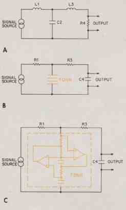
Fig. 1—Derivation of the FDNR. A third-order LC filter (A) transforms to a third-order
low-pass filter (B), implemented as shown in (C).
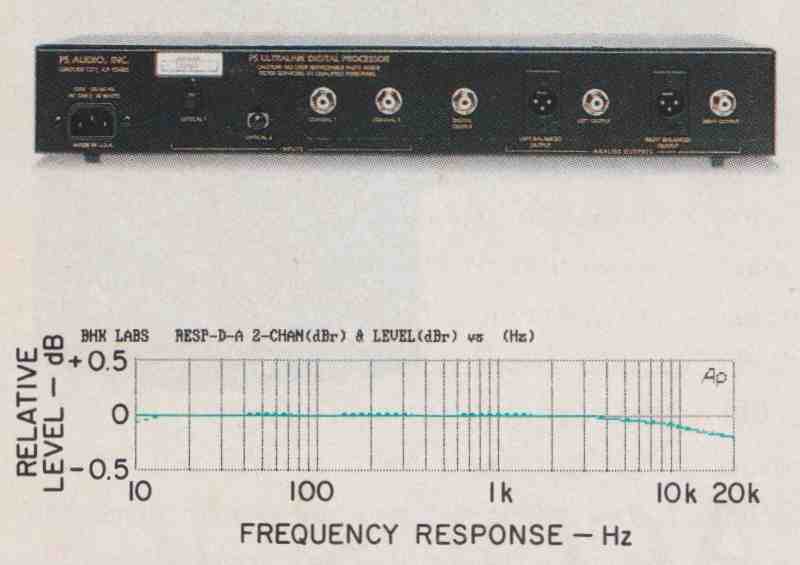
Fig. 2—Frequency response.
Frequency response without de-emphasis is plotted in Fig. 2. The response with de-emphasis was virtually identical to that shown in the figure, so the de-emphasis error itself, which is the difference between the two conditions, is less than ± 0.1 dB over the audio range. This is the lowest error for this test I have seen in any converter so far. Square-wave and impulse responses (not shown) were similar to those of the NPC SM5813 commonly used in other converters. This filter exhibits linear phase characteristics; it also clips the ringing on full-scale square waves at the full-scale point, leaving only those portions of the ringing that point toward the “0” line. The filter’s ringing is normal and linear at levels below full scale.
Linearity of the UltraLink is extremely good. As Fig. 3 shows, deviation from linearity is less than 1 dB down to almost -110 dB -- an excellent result, to say the least. The “fade-to-dither” test on the CBS test CD gave essentially the same results.
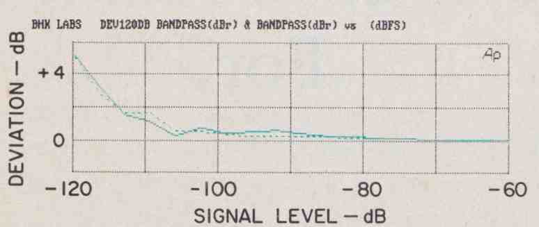
Fig. 3—Deviation from linearity.
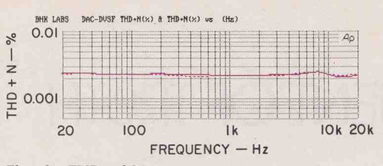
Fig. 4—THD + N vs. frequency at 0 dB.
Figure 4 shows THD + N at digital full scale. Results are shown for 16-bit data words (the normal CD word length; measured distortion gets lower with 18-bit words). The results indicate that the S/N ratio of this unit is very good, as will be seen soon. Figure 5 shows 1-kHz THD + N versus signal level, for 16-bit words.
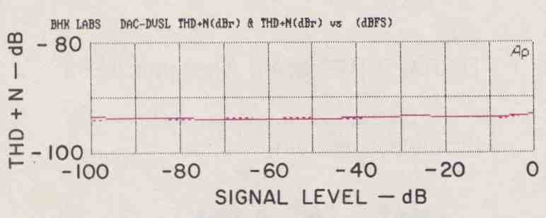
Fig. 5—THD + N vs. signal level.
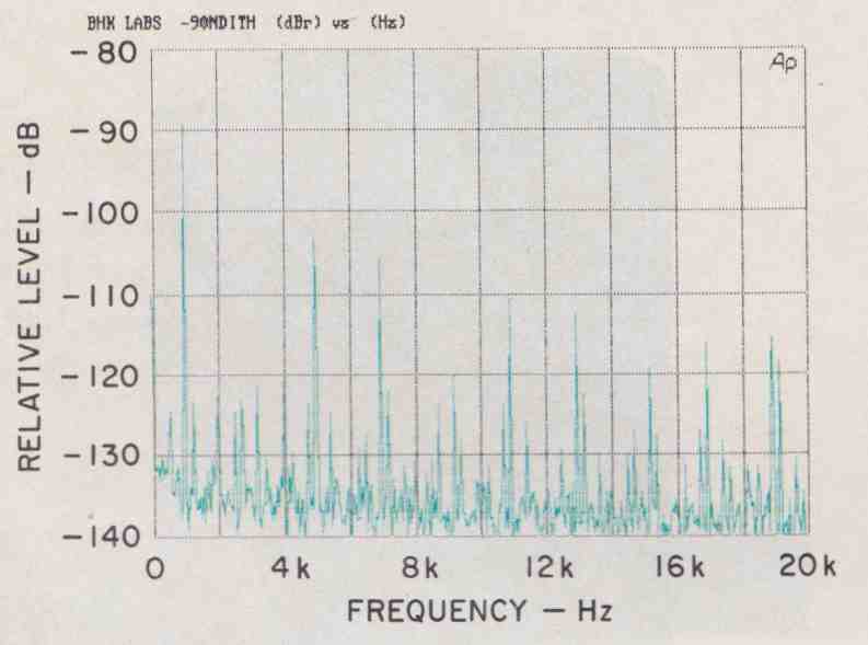
Fig. 6—Analysis of undithered, 1 -kHz signal at -90 dB.
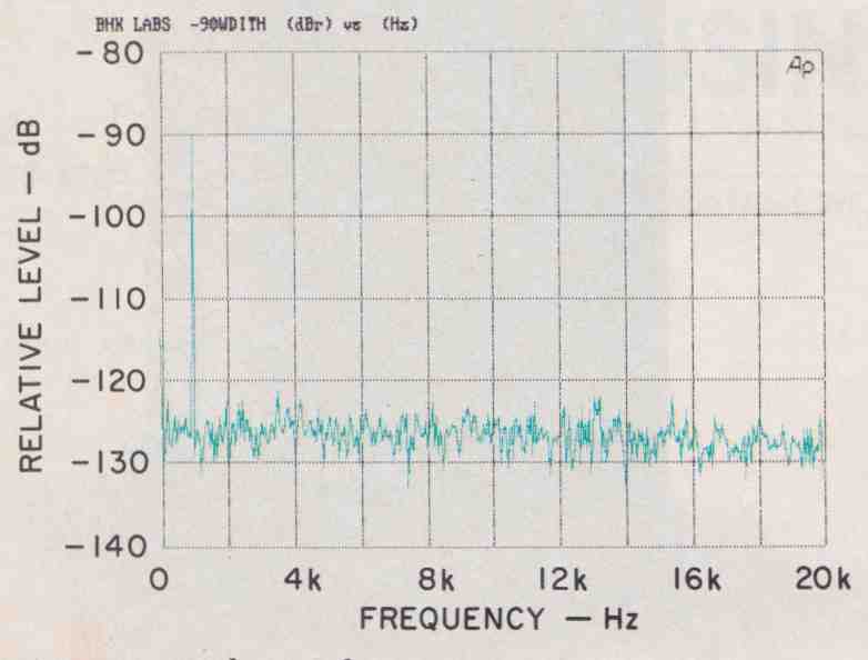
Fig. 7—Analysis of dithered, 1 -kHz signal at -90 dB.
I also made some spectrum analyses of both dithered and undithered 1 -kHz signals at -90 dB. The spectra graphically show the effects of dither on the low-level linearity of the CD digital process. Without dither, the signal is full of nasty harmonics and other unwanted components (Fig. 6). Also, the third harmonic is conspicuously absent, because the duty cycle of this undithered signal’s waveform mathematically happened to just about eliminate that harmonic. The spectrum of the signal with tri angular dither added is such an improvement (Fig. 7)! The noise floor has come up about 10 dB, and the harmonics have gone away.
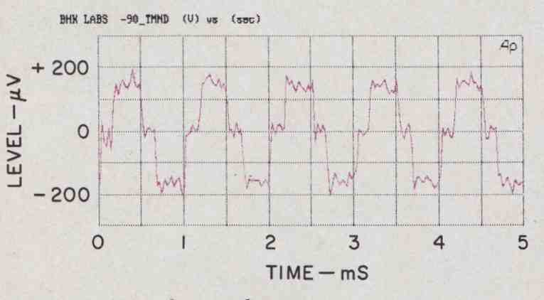
Fig. 8—Waveform of undithered, 1 -kHz signal at —90 dB; see text.
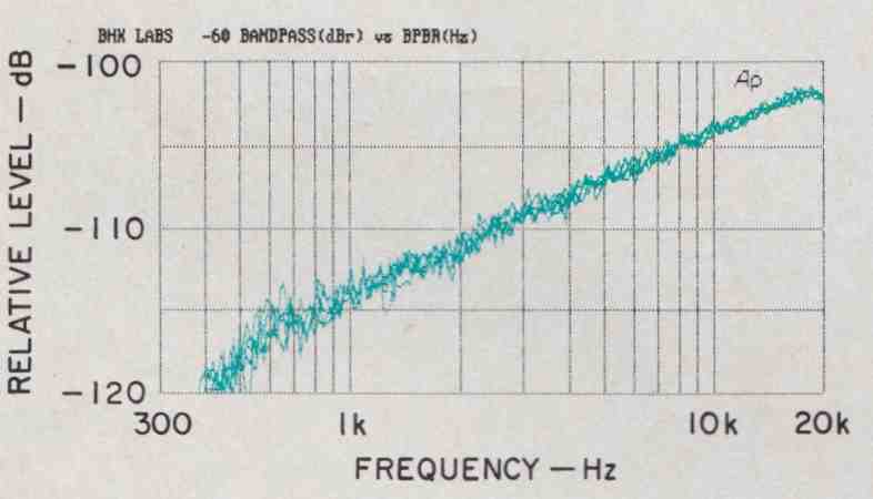
Fig. 9—Quantization vs. frequency at several modulation levels; see text.
One thing that really impressed me about this converter is that its overall S/N was good enough to let me really see a -90 dB undithered waveform. Witness this in Fig. 8, where the signal’s three-state character (one LSB plus, “0,” and one LSB minus) is quite easy to see. Many other D/A converters that I have measured obscure such low- level signals with system noise. I should mention, though, that many good CD players are quiet enough for such signals to be seen in their analog outputs.
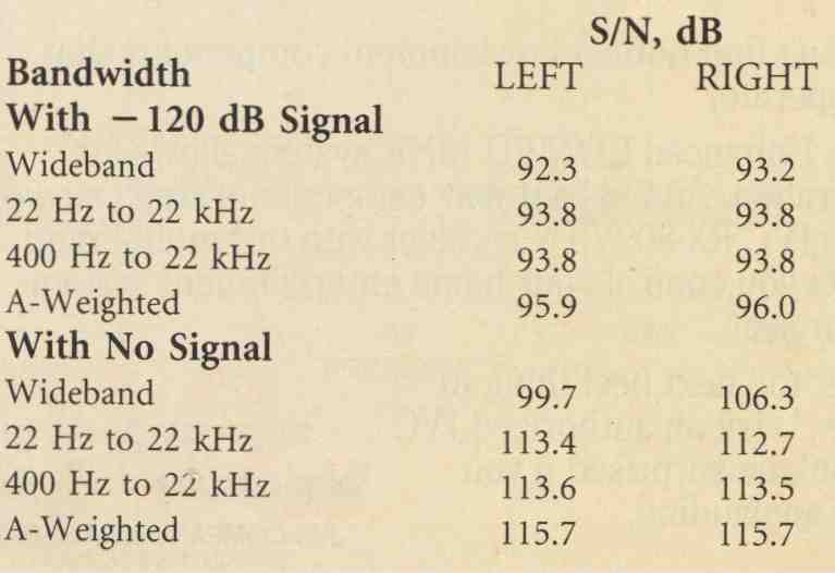
---Table 1—Signal-to-noise ratios. Quantization noise was —94.2 dB for the
left channel and —95.0 dB for the right; dynamic range was 98.3 and 102.0
dB, respectively, for the two channels.
Table 1 lists S/N for various bandwidths, plus EIAJ quantization noise and dynamic range. What is especially impressive are the SIN ratios at digital zero, i.e., with the digital signal off (as op posed to being on but at a very low level, like -120 dB). This is not usual with most external D/A converters. A test devised by Richard Cabot of Audio Precision looks at quantization effects as a function of frequency and the modulation level of a 41-Hz signal that varies from -60 to -100 dB in 10-dB steps. Good performance in this test is the degree to which the sweeps for different levels overlay each other. As Fig. 9 shows, the UltraLink’s performance is very good.
Interchannel crosstalk in this unit was absolutely outstanding. It was about 120 dB down at frequencies up to 1 kHz and approached -100 dB at 20 kHz.
A few final comments on miscellaneous measurements: The UltraLink’s absolute signal polarity is correct when the front-panel in version function is not invoked. Audio output impedance measured about 40 ohms. Output d.c. offset was a maximum of -3.8 mV in the negative-phase output of the left channel. Overall, the UltraLink is one of the best, if not the best, D/A converters I have tested.
Use and Listening Tests:
Analog signal sources in my system during the period of review included a Nakamichi ST-7 FM tuner and 250 cassette deck, and a Technics 1500 open-reel recorder. On the digital side, I used Krell Digital MD-1 and PS Audio CD transports to feed the UltraLink, a Counterpoint DAb, and other, experimental, converters.
Preamps used were a First Sound Reference II and a Counterpoint SA-5000. Power amps used were Crown’s Macro Reference, Parasound’s HCA-2200-II, and a prototype pair of Quicksilver Audio Ml35 mono tube units. Loudspeakers used were Win Research SM-10s and B & W 801 Matrix Series 3. Additional listening was done with my Stax SR-Sigma Pro 1 headphones driven from a power amplifier with the Stax SRD-7 Professional energizer.
I remember when I first heard the Ultra-Link; Bob Odell of PS Audio brought one up for me to try out. I was then using the VTL Straight-Line. After going back and forth between these converters a few times, I realized that the UltraLink was indeed a very good-sounding unit. As a matter of fact, I bought it to use as a measurement reference (and of course, to enjoy listening with)! The unit tested for this report was a review sample; if anything, it sounds a little better than the original one I bought.
During my testing, I found no operational glitches. The UltraLink operated perfectly, which is as it should be. The sonic attributes that distinguish it from many other D/A converters I have tested include finer resolution, greater detail, better soundstaging and space, and generally more musical believability. This is a good- sounding D/A converter that deserves all the praise it gets.
(This article adapted from Audio magazine, August 1993.)
============
Also see: