Optimum geometry of tonearms has been the subject of several articles over the past three decades, the earliest complete mathematical study being that of H.G. Baerwald in his paper on optimum geometry in 1941, where an analytical study of tracking error distortion showed that optimum geometry of a tonearm of given effective length will have a corresponding offset angle and overhang. Further, the arm should zero at two positions on the grooved surface of a phonograph record given the minimum and maximum radii where the signal will be encountered. Recently [late 1979] the subject has been brought up by The Audio Critic, and in surveying the literature, we found papers on the subject of lateral tonearm geometry by B.B. Bauer in 1945 and John Seagrave in 1956/1957 that presented data essentially the same as that of Baerwald. Seagrave stated in his paper, "Hear, then, the sad facts: Few of the commercially available arms are designed to give minimum tracking distortion on the largest LPs they are supposed to handle!" Consumer Reports in 1956 stated in a survey of high-fidelity pickups that "the best performance was often obtained when an overhang other than that recommended by the manufacturer was used." In these "modern" times of computers and high technology, it is interesting to note, according to our calculations, that only a small group of manufacturers of tonearms are utilizing optimum lateral geometry. One would assume there would at least be agreement on this design parameter. Recently, Paolo Nuti used simple trigonometry to present some easy-to-use equations for measuring and calculating lateral tracking error, and provided a program for use on the Hewlett-Packard 67/97 scientific programmable calculators.


Baerwald found "that both absolute and nuisance effects of tracking distortion are considerably greater than commonly assumed, published values usually being underestimates, due to omission of rigorous procedure." Basically, the absolute error of the tracking angle is not important but rather, the weighted error which is the angular error divided by the groove radius. The idea is to reduce the weighted tracking error over the entire grooved surface minimizing the peak weighted error. Baerwald derived his formulae from a second-order Chebyshev approximation used in electric wave filter design. As angular error increases, so does stylus friction, according to Baerwald, where the vertical component of friction increases in direct proportion to the angular error.
The higher the stylus friction (angular error), the greater the skating force. A pivoted tonearm with zero tracking error (tangential type) will maintain a constant stylus friction for a given recorded velocity. In order to get a fixed offset arm (most commonly available) to have as near constant friction as possible, the angular error over the grooved surface would have to be minimized. With Baerwald's equations, there will be slightly more overall angular error than in an arm optimized for angular error but, for most arms available, the optima weighted error equations still result in lower overall angular error. With simple signals, for instance a sine wave, distortion is essentially second-order harmonic. This kind of distortion is not a grossly unpleasant sort, but when reproducing music, simple signals are usually not encountered.
With the complex signals of recorded music, according to Baerwald, second-order cross-modulation products are the prevalent distortion components. Cross-modulation distortions according to The Audio Critic are " time-dispersive and therefore much more audible and disturbing." Geometric Considerations Basically, optimum geometry can be summarized in three simple equations the determination of null radii, the optimum offset angle, and the optimum overhang for a given effective length. The equation derived through a second-order Chebyshev approximation for the position of the null radii by Baerwald is given by:
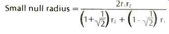

...where r1 and r2 are the inner and outer maxima of encountered signal. The equation for optimum angular offset is given by:

...where a is the angle of the offset for the tonearm in degrees and L is the effective length of the tonearm. The equation for optimum mounting center is given by:
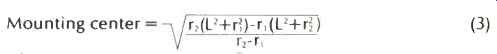
...
where L is the effective length, r, is the inner null radius, and r2
is the outer null radius.
From the above equations optimum tonearm pivot-to turntable spindle distance (mounting center) can also be determined from the law of cosines:

...where L is the effective length, r1 is null radius 1, and a is the offset angle in degrees.
The following is an actual numerical example. Given r, =2.375 in. (minimum groove radius) and r2 = 5.75 in. (maximum groove radius), then

The above results are the optimum values for the minimum and maximum signaled grooves encountered on a 12 in. LP. Given an effective length of 9 inches, calculate the offset angle.

Therefore the arc sine of 0.4088 = 24.13 degrees.
From the offset angle and one of the null radii, calculate the mounting center of the tonearm.

Overhang for the stylus is the effective length minus the pivot to spindle distance (9 in.-8.28 in.=0.72 in.). Figure 1 shows the relationship of the offset angle to the effective length to the tonearm mounting center to the null radii.
Null Radii
On a record surface a pivoted arm will traverse an arc.
Through this arc, with most arms, the stylus will go through two points where the stylus is tangential to the groove in other words, there will be zero error at each of those two points. In addition, the stylus will encounter maximum error, depending again on the design of the arm, in three places.
Some arms have near zero error at the beginning and end of the record, creating a larger error in the middle. To find the radius of greatest angular error between the null radii, given the effective length and the overhang, the equation is: Radius of greatest angular error between nulls =

...where L is the effective length of the tonearm and OH is the overhang: Given an arm of 9-in. length and an overhang of 0.5 in., calculate the radius or maximum error between the nulls.
Radius of greatest angular error from (5) =

Note that the greatest weighted error will not occur at the same point as angular error but will be quite close its solution is determined by an iterative technique and will not be discussed here.
An arm will have two maximum error points if it is made to zero at or near the innermost groove and somewhere in the middle of the record. Most arms are designed this way. Optimum arm design has the maximum error at three points the outermost groove, the innermost groove, and between the null radii. Again, it is not angular error but weighted error. With optimum design the weighted error is the same for each peak. As in Baerwald, the tracking distortion is directly proportional to the weighted error and inversely proportional to the groove radius. To find the exact angular error of a given arm, given the offset angle, the effective length, and the overhang for any given groove radius, the equation is:

...where R is the radius for which the error is to be found, L is the effective length, OH is the overhang, and OA is the offset angle.
Given an arm of 9-in. length, an offset angle of 24 degrees, and an overhang of 0.62 in., calculate the angular error for a 4in. radius.
Angular error from (6) =

One of the major problems when calculating optimum design parameters occurs with the source itself. What are the minimum and maximum groove radii that will be practicably encountered? A number of years ago this would have been a difficult problem, because the record manufacturers had not standardized on the record sizes. Since 7-, 10-, 12-, and 16-in. records were being produced, arm geometry had to be a compromise. Now that all are using a standard 12-in. format for high-fidelity use, the problem boils down to settling where the inner groove is to be. Practically all records have an outermost groove radius of 5.75 in. (146.05 mm). The innermost groove on some records has run almost to the record label, which is at 2 in. NAB standards call for a minimum of 2.25 in. (57.15 mm). Most records, aimed at the audiophile market, never reach 2.375 in. (60.325 mm), a more realistic figure for high-fidelity use than the NAB standard 2.25 in.
Generally, the smaller the area over which the arm is to be optimized, the smaller the peak weighted error will be. So, within the limits of practicality, arms aimed at the audiophile market should be optimized for records whose grooves will end up between 2.375 in. and 5.75 in., as proposed by Bauer.
These values give null radius positions of approximately 2.6 in. and 4.76 in. (66.04 and 120.9 mm, respectively).
Effective Length
Effective length of the tonearm is the distance from the pivot of the arm to the cartridge stylus tip. This dimension is almost always determined from the design specifications and is very difficult to measure accurately once the tonearm is assembled and the cartridge mounted. Generally, as effective length increases the tracking error decreases a pivoted tonearm of infinite length will have zero tracking error. Since it is impractical to make such a tonearm, most manufacturers design their products' effective length with other factors in mind such as effective mass, resonance, the size of the turntable base upon which the arm is to be mounted, as well as decreased tracking error and distortion. From a design standpoint, it is desirable to have the longest effective length practical.
Overhang
Overhang is a figure derived from subtracting the distance from the pivot to spindle center from the effective length of the tonearm. Except for a small number of arms with an adjustable pivot, once the arm is mounted and the overhang set, the effective length is fixed. If the arm is mounted precisely at the correct point, the effective length will be that which was intended.
From equation 3 it can be seen that the mounting center of the tonearm is a precisely determined figure in a mathematical relationship to the other lateral components of the arm.
However, our study reveals that most tonearm manufacturers appear to have overlooked this figure in their production of tonearms. As an example, many of the Japanese arms listed in Table I have a specified overhang of 15 mm. Unfortunately, the only effective length that will optimally have an overhang of 15 mm is 274 mm (10.787 in.), a length larger than many turntable bases can practically accommodate. A major problem is locating the precise pivot position on the turntable base. Most manufacturers of separate tonearms have failed to supply a precise means of locating the tonearm on the turntable base, thus negating the parameters designed into the tonearm. In our opinion, it behooves the tonearm manufacturers to supply a means of precisely locating the mounting center for their tonearm so that the carefully designed parameters are maintained. Therefore, assuming that the tonearm pivot is mounted correctly according to the manufacturer's specification, the overhang template supplied with the tonearm may be valid for the design of that tone arm, though not necessary optimally. Should the mounting hole center be located wrongly, the overhang templates will most probably be invalid for the tonearm. In order to decrease the possibility of imprecisely locating the tonearm pivot, some tonearms are designed with an adjustable pivot that is used after the tonearm is mounted. Generally, a slot is made in the mounting board, located lengthwise along the line extending from the spindle center to allow for maximum range of adjustment. On tonearms whose pivots are fixed the manufacturer has included two mounting slots in the head shell so as to permit sliding the cartridge to the correct position for the desired overhang. The adjustable pivot arms usually have two round mounting holes in the headshell. With these arms, overhang distance is of little concern to the installer, because the arm is usually zeroed in on a null template. With these arms, effective length will vary somewhat according to the cartridge used (most are standard 0.375 in. stylus tip to mounting hole center), but also the offset angle and overhang will vary with this type of tonearm. Since the inner null radius on many adjustable pivot arms is 2.375 inches, tracking error may be reduced at that point but it may not be optimum. The second null radius usually ends up in a location that will prevent optimum tracking distortion characteristics over the entire record.

Fig. 1 Relationship of the lateral components of a tonearm.
Offset Angle
The offset angle of the tonearm, as seen in Fig. 1, is taken from an imaginary line drawn from the pivot center through the stylus tip and a line parallel to the cartridge body through the stylus tip. Basically, this angle is a result of design specification and not a measurement after the fact of assembly. If the effective length, the overhang, and one of the two null radii are known, the offset angle can be easily determined by the solution of that triangle. All the factors fit together like a jigsaw puzzle a wrong dimension simply will not fit. For example, given an effective length of 229 mm, an overhang of 15 mm, and a null radius of 60.325 mm, calculate the offset angle of this tonearm.

The manufacturers of the tonearms listed in Table 1 supplied the effective length, overhang, offset angle, and null radii for their tonearms. The submitted data was checked to ascertain that the data were consistent. However, some of the data supplied did not fit the specifications. In one instance, the null radii were recalculated according to the submitted data and were found to be different from those given in the manufacturer's specifications.
A common mistake among many audio dealers, advertising copywriters, and audiophiles is to attribute the geometry of an arm to its shape. A tonearm shape is probably more the result of industrial or artistic design than geometric considerations. There really is no superior shape for tonearm geometry since resonance, stiffness, mass, lateral balance, and aesthetics will determine the final shape. With these factors in mind, many of the tonearms in Table I can be optimized with little change in the production process. It would be false to assume that a correction in lateral geometry would have all tonearms looking alike because a change to optimum geometry would be visually imperceptible and the general appearance would remain intact.
Optimum lateral geometry is important, but other parameters and considerations, such as mass of the arm, moment of inertia, resonance characteristics, cartridge compatibility or universality, tube stiffness, vertical tracking angle, bearings, etc., all contribute to the final sound of the arm-cartridge turntable system. If factors such as those cited above are not properly executed, the contribution of optimum geometry will be lost. The improvement of sound resulting from optimum geometry is subtle but detectable, if it is not overshadowed by other design errors. Even if optimum design is not entirely practical, it is to be hoped the tonearm manufacturers will make absolutely certain that the instructions for setting up their tonearm are detailed and correct according to its design parameters.
Bearings
Correct lateral alignment of vertical bearings is important for maintenance of designed geometry and cartridge azimuth. If records were perfectly flat, the angle of the bearings affecting the vertical axis would not be critical. However, that is not the case, and with vertical tracking angle (VTA) adjustments on some tonearms, the headshell will not remain parallel to the record surface as the arm moves up and down in the vertical axis since the plane of the cartridge body changes with respect to the record surface. If the angle of the vertical bearings is perpendicular to the line through the offset angle, there will be only one angular change, that of the VTA. If, however, the bearings are not perpendicular to that line, the plane generated becomes a compound angle problem the cartridge plane twists in two angles (azimuth changes). Bear in mind that when setting up the arm, the instructions usually state that a mirror be used to check the front of the cartridge relative to the record surface. As the arm traverses warps or is raised and lowered in the pivots for VTA, the parallel plane is lost in proportion to the difference in angle from perpendicularity from the plane of the cartridge. Visualizing this isn't easy, but if the arm could be rotated up in the vertical plane until it was straight up, the arm whose bearings were in alignment with the offset angle would have the front of the cartridge still parallel to the record surface, whereas the arm not so designed would have the right front edge of the cartridge higher than the left front edge. The problem becomes very complex with unipivots where, with fixed bearing arms, the solution is simple. The resolution of the vectors to bring about the same effect in the unipivot arms is complicated because of counterweight placement. Generally, if the vertical bearings are in alignment with the offset angle, the problems with warp and VTA are made less severe because a simple angle is generated, rather than a compound angle that is typical with many arms currently available. In addition, the height of these bearings is equally important for minimization of warp wow.
Table I seems to be divided on the issue of vertical bearing angle. There should be no disagreement on the preservation of cartridge azimuth. At the moment we are not aware of any literature concerned with the problems of azimuth alignment.
=============

Explanation of Table I
The 22 tonearms listed are representative of the majority of arms currently available. Only three arms listed have their geometry optimized, using Bauer's criteria for inner and outer maximum groove radii, when set up according to the manufacturer's instructions. A number of the arms have been optimized using Baerwald's equations, but used inner and outer radii other than those proposed by Bauer.
The first five columns of figures represent manufacturer's tonearm dimensions as supplied. Most of the data were supplied by the manufacturers, 'and some were calculated. Note that the closer the null radii are to 66.04 mm and 120.9 mm, the closer the arm will be to optimum when set up correctly.
The next two columns contain data from Table V for comparison to what the listed arms would be ideally for their effective lengths. The next three columns are the actual absolute weighted errors in degrees percentimeter at the inner groove (60.325 mm), between the nulls, and the maximum radius (146.05 mm). Note that the weighted error between the nulls was calculated using an iterative procedure on a computer.
The next column contains the maximum optimum weighted error for an arm of the given effective length. This error will be approximately the same at the innermost, between the nulls, and maximum grooves. For example, for an arm that has a very low error at the innermost groove, weighted tracking error will be compromised over the rest of the record. The next column for reference is the maximally encountered angular tracking error. Generally the maximum error will occur at the outermost groove. The next column is the maximum angular error for an optimum arm of the same length. On occasion this figure will be slightly larger than the actual arm as designed (it was designed for angular error, not weighted error). The next column denotes the method of pivot location if the arm is fixed, a round hole would be drilled; if adjustable, a slot to allow the overhang to be adjusted. The last column denotes whether the tonearm's vertical bearings were aligned so that they were perpendicular to the offset angle line (yes or no). Since these figures represent "as set up" dimensions, choice of arm should not be based on geometry per se, inasmuch as alignment devices such as the jML and DB protractors and the Dennesen Soundtracktor give the installer a convenient way of aligning the arm-cartridge system to optimum values.
The SAEC WE-308 SX arm design is based upon research done by the Sansui Electric Co. The AES preprint 1390 (D-5) derived the optimum pivot position from a kinematic point of view, with the mass of the arm, the location of the center of gravity, and the moment of inertia around the system's center of gravity. Resonance was the engineering problem being solved. For this particular arm, it is not advised to optimize the geometry, or the resonance of the system will change to such an extent that the arm will not track properly.
===============
Tonearm Setup Errors
Murphy's Law dictates that practical problems will arise both for the professional setting up audiophile quality equipment and the user trudging through the tonearm manufacturers' sometimes confusing and inaccurate setup instructions. Typical problems that may arise in the course of an installation follow.
1. The cartridge has been pushed all the way forward and the proper overhang still cannot be achieved.
2. The overhang is correct according to the instructions, but the mounting hole was drilled in the wrong place.
3. With a movable pivot arm, there appears to be too little forward adjustment travel and the stylus will not reach the template null and "zero" simultaneously.
======

TABLE II: Optimum parameters for two different tonearms.
Arm 1 | Arm 2
Effective Length 200 mm 300 mm
Offset Angle 27.854° 18.149°
Overhang 21.055 mm 13.606 mm
Null Radii (for both arms) -- Inner = 66.04mm; Outer =120.9 mm.
======
Occurrences such as these will frustrate even the most patient audiophile and technician. Both will throw up their hands in defeat and assume the fault was theirs in that they left out an important step. Although one should be as accurate as possible with the setup, many times the instructions accompanying the tonearm are insufficient, in error, or poorly translated. The consumer is seldom aware of the geometric interaction of the lateral tonearm components; errors of a degree here or a millimeter there go unnoticed or are considered insignificant, while actually such errors have considerably altered the geometry of the tonearm.
As a reference, it is important to consider the null radii. The positions of the radii actually represent the design of the arm being installed more than any other parameter. If after careful setup, the arm does not "zero" on its designed null radii, an error may have occurred either in setup or possibly on the drawing board. For the following discussion the relative changes of the nulls will be considered with respect to common errors in setup.
1. What effect does a "small" error in offset angle have on null radii, and does arm length make a difference? Referring to Table II, suppose the correct geometry of both arms is altered by adding a 0.4° error to the offset angle, leaving all the other parameters the same except, of course, the null radii. The offset angles are changed to 28.254° (27.854° +0.4°) and 18.549° (18.149° +0.4°). It is easy to make a 0.4° error; most people do it inadvertently. The results in Table Ill show that with only 0.4° error, the small arm misses the nulls by-2.707 mm and +5.159 mm, while the large arm increases to-4.17 mm and +8.14 mm. Note that the longer the arm, the more critical it is to get the offset angle exactly right. Errors over two degrees may put the null radii somewhere off the record hardly optimum.
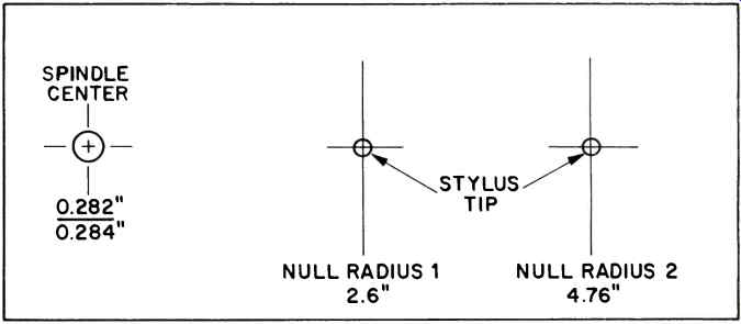
Fig. 2 Dual null radius protractor.
2. What happens when small errors in overhang occur? Using the same optimum tonearms as in Table II, an error of +1 mm will be induced in the overhang. This kind of problem can occur if the arm is mounted in the wrong position but the manufacturer's instructions were to align the overhang of the stylus with reference to the headshell. Since no cross checks are supplied, it is assumed that the job was done correctly. Incidentally, almost no manufacturers supply the consumer with geometric cross-reference checks for the arm setup, especially for those arms with particularly confusing instructions. Referring to Table IV, with +7.539 mm and -7.551 mm translational error in the position of the null radii for the small arm and +13.955mm and -13.961mm in the large arm, small errors in overhang become crucial. Actually, if the manufacturer supplied an overhang template to check the overhang over the spindle, the problem would be minimized to a large extent. Overhang changes very slowly compared to changes in offset angle and arm length. The length of overhang is more important than the absolute accuracy of the mount. Also, the longer the arm, the more critical the overhang dimension.
========================

Table III Change in null radii when 0.4 degree is added to the optimum offset angle of Table II tonearms.

Table IV Change in null radii when 1 mm is added to the optimum overhang of
Table II tonearms.
===========================
3. A movable pivot arm is mounted on a turntable with a predrilled mounting slot. In the course of moving the pivot towards the null template, forward travel stops in the arm before the arm reaches the zero position on the template.
This is unfortunately a more common problem than might be realized. A few of the more popularly priced direct-drive turntables have convenient precut mounting boards. At this point, aesthetics got into the way of performance. Many movable pivot tonearms are relatively short, e.g., 9 in. (229 mm), and platters on the turntables are oversize, up to 13 in. diameter (330.2 mm). In order to preserve aesthetics and prevent a "cluttered look," the mount is located a comfortable distance from the platter, and the slot center may be located at least 0.5 in. (12.7 mm) from where it should be. The result is that the arm probably ends up with its null radii off the record surface (a 3-mm error will accomplish this). The actual results are the same as for example 2, where the offset angle and effective length are "frozen" the overhang gets the short end (no pun intended). From the above it can be readily seen that even using care, 3. A movable pivot arm is mounted on a turntable with a predrilled mounting slot. In the course of moving the pivot towards the null template, forward travel stops in the arm before the arm reaches the zero position on the template.
This is unfortunately a more common problem than might be realized. A few of the more popularly priced direct-drive turntables have convenient precut mounting boards. At this point, aesthetics got into the way of performance. Many movable pivot tonearms are relatively short, e.g., 9 in. (229 mm), and platters on the turntables are oversize, up to 13 in. diameter (330.2 mm). In order to preserve aesthetics and prevent a "cluttered look," the mount is located a comfortable distance from the platter, and the slot center may be located at least 0.5 in. (12.7 mm) from where it should be. The result is that the arm probably ends up with its null radii off the record surface (a 3-mm error will accomplish this). The actual results are the same as for example 2, where the offset angle and effective length are "frozen" the overhang gets the short end (no pun intended).
==========

TABLE V Optimum values for tonearms (200-250 mm) and angular error.
This table gives optimal values for arms tracking within 60.325 mm and 146.05 mm (2.375 in. and 5.75 in.) inner and outer grooves. The last three columns represent the actual angular error for the inner groove, between the null radii, and the outer groove. This table can be used for determining the mounting position for drilling the tonearm mounting board.
===========
From the above it can be readily seen that even using care, errors that appear small can create large problems. Most setup procedures supplied by the tonearm manufacturers are inadequate given the tools supplied for the installation-a paper template, whose accuracy is questionable, and many times a confusing set of instructions. The manufacturers should consider providing a cross-reference check template to validate the designed null radii. In tonearms that have a continuously variable VTA adjustment, the lateral error might be so far off that a change in VTA might never be heard.
Optimizing Tonearm Geometry
If the tonearm is not optimized, do not be overly concerned, since the result is not wholly fatal. It is feasible to optimize the lateral geometry of the arm if it is already mounted, but only if the arm is reasonably close in its overhang so that the optimization procedure will not compromise the integrity of the arm-cartridge system. For example, on some adjustable pivot arms where the headshell has no mounting slots, the cartridge cannot be twisted in the shell to achieve a line-up with an optimum null radius template if both mounting screws are in place. (At least one dealer we know of connected a cartridge with only one screw in such an arm so as to achieve optimal geometry, but ended up negating all of the good characteristics the arm had a pyrrhic victory at best.) Another instance occurs in the arms that have correct vertical bearing alignment with the cartridge. Here, one has to decide on a compromise on most arms designed with correctly aligned bearings, a change in azimuth is less critical than maintaining optimum lateral geometry. Assuming the tonearm's mounting hole is within a few millimeters of optimum and the headshell has slots to allow the cartridge to be twisted and moved, the arm can be optimized by using a null radius template. On other arms, where the mounting hole is out of range, it is up to the user to decide whether the trouble warrants re-drilling a new mounting board or leaving the arm as is.
Here it is necessary to discuss the tools that will be required for the optimum tonearm-cartridge setup. Recently, three manufacturers have introduced alignment devices to accomplish an optimum tonearm-cartridge setup JML Company, DB Systems, and Dennesen Electrostatics.
The JML Universal Tonearm Alignment Protractor is basically a coated-cardboard template with null radii optimized for a record surface within the radii of 2.375 and 5.75 inches.
The template and instructions are available for $3.00. It is much better than attempting to construct one as is shown in Fig. 2. The instructions, though adequate, could have been more detailed. The JML Company assumes that the consumer will drill the mounting hole and requires the tonearm effective length to be measured with a cartridge already mounted.
This is a difficult procedure, but the instructions say that only approximation is necessary. It is much safer to use the manufacturer's specification for effective length and calculate the optimum overhang and tonearm mounting center from equation 3 once the offset angle is calculated from equation 2. Table V presents the optimum overhang and offset angle for varying effective arm lengths. Note that the mounting center is the effective length minus the overhang. Small inaccuracies are taken care of using the null radius system.
Geometrically speaking, if the cartridge nulls at both radii of the JML template, the overhang and offset angle will automatically be correct. If the tonearm has already been mounted and its measured dimensions are not too far off, the nulling system can be used. The procedure can be frustrating, but patience will get accurate results. One point which may not be immediately obvious: The protractor (template) must be rotated to a different position for zero alignment error at each null radius.

Above: DB Systems DBT-10 Phono Alignment Protractor
A more elaborate version of the JML protractor is the DB Systems DBT-10 Phono Alignment Protractor. This unit is made of mylar and uses the same nulling system as the JML. A good set of instructions comes with the $19.95 unit, which also allows the user to measure tracking angle error.
There is only one rotated position of the protractor that will be correct for any one arm of given effective length. If this position could be fixed, nulling would only have to take place at one radius and could be performed in one step. The Dennesen Geometric Soundtracktor has recently been introduced to perform this function. Available in two models-a plastic version for $35.00 and a metal version for $100.00 the user can, in a single step, align overhang, offset angle, and both null radii, provided the tonearm has an obviously marked pivot center. We have used this tool for the past few months and recommend it without reservation. The instructions are simple, with the actual procedure not taking more than a few minutes. The Soundtracktor will quickly indicate if the tonearm is optimally set up and will make realignment of the cartridge an easy job. The Dennesen Soundtracktor is accompanied by a vertical tracking angle (VTA) reference gauge, which looks like a tonearm rest post and a bubble level for the tonearm. Although the unit does not determine VTA, it does establish the reference number for each record in a collection, where the sound is most focused. Once the VTA is established for a record, it is a simple matter to set the tonearm to the correct VTA number, established earlier. The above-mentioned alignment tools are available from JML Co., 39,000 Highway 128, Cloverdale, Calif. 95425; DB Systems, P.O. Box 187, Jaffrey Center, N.H. 03454; and, Dennesen, P.O. Box 51, Beverly, Mass. 01915.
Calculator Hints
With the advent of inexpensive yet sophisticated scientific calculators, solution of the equations presented in this paper becomes a practical consideration for interested audiophiles as well as engineers. Those who have programmable scientific calculators such as the Hewlett-Packard 67/97 can find quick repetitive answers easily, thus this section is not really aimed at them because the capability of programming already qualifies them to work with algebraic equations.
It is assumed that for practical purposes, the calculator has trigonometric and standard algebraic functions, one memory, and no algebraic hierarchy except single argument functions such as square root. For example, the very inexpensive Texas Instruments TI-30 would be a good choice. Users with more sophisticated equipment can modify the procedure. The calculator mode, for simplicity, will be fixed at two decimal places.
Equations 2 and 4 are of the most interest since they calculate offset angle and overhang.
Example 1: Solve the following equation for offset angle:

Example 2: Solve the following equation for mounting center:

Refer to Table 7 for the step-by-step procedure.
The procedures are general and may not be directly applicable to all calculators. Since the output column gives the intermediate results, one can modify the routines for his own calculator.

Table VI Calculator steps for calculation of optimum offset angle.

Table VII Calculator steps for calculation of mounting center and stylus
overhang.
References
1. Baerwald, H. G., "Analytic Treatment of Tracking Error and Notes on Pick Up Design," J. Soc. Mot. Pic. Engrs., 37:591, Dec., 1941.
2. Bauer, B. B., "Tracking Angle in Phonograph Pickups," Electronics, p. 2, Mar. 1945.
3. Consumer Reports, 21:245, May, 1956.
4. Seagrave, John D.: "Minimizing Pickup Tracking Error, Part I," Audiocraft Magazine, 1:19, Dec., 1956.
5. Seagrave, John D., "Minimizing Pickup Tracking Error, Part II," Audiocraft Magazine, 2:25, Jan., 1957.
6. Seagrave, John D., "Minimizing Pickup Tracking Distortion, A Sequel," Audiocraft Magazine, 2:22, Aug., 1957.
7. Hiscocks, Peter; "Tonearms," Audioscene Canada, Nov., 1975, p. 64.
8. Kogen, James H., "Record Changers, Turntables, and Tone Arms-A Brief Technical History," Jour. Audio Eng. Soc., 25:749, Oct./Nov., 1977.
9. Bauer, B. B., "The High-Fidelity Phonograph Tranducer," Jour. Audio Eng. Soc., 25:729, Oct./Nov., 1977.
10. "Have Tone Arm Designers Forgotten Their High-School Geometry?" The Audio Critic, 1:31, Jan./Feb., 1977.
11. "Cartridge/Arm/Turntable Followup: Loose Ends and New Developments," The Audio Critic, 1:43, Spring/Fall, 1978.
12. Nuti, Paolo, "Le Caratteristiche Geometriche dei Bracci in Rapporto all' Errore Radiale di Tangenza," I .A.F.2, Sept., 1977 Supplemento al n. 63 di Suono.
13. S. Takahashi, S. Taguchi, N. Kaneko, and Y. Fujimoto, "The Optimum Pivot Position on Tonearm," A.E.S. Preprint 1390 (D-5) presented at the 61st Convention, Nov. 3-6, 1978, New York.
14. Stevenson, J.K., "Pickup Arm Design," Wireless World, May & June, 1966.
Also see:
Article by Martin D. Kessler and B. V. Pisha (adapted from Audio magazine, Jan. 1980)
= = = =