author: RICHARD KAUFMAN
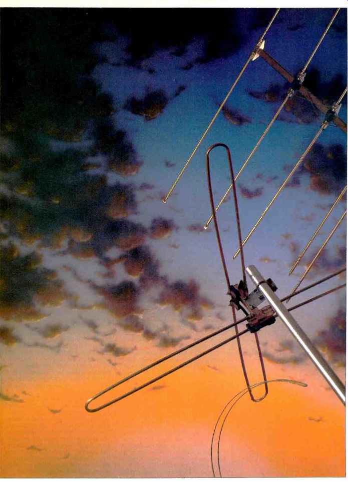
A good antenna will make an inexpensive receiver outperform all but the very most expensive state-of-the-art models, but most owners of FM stereo equipment continue to use a 50C "folded dipole." The best tuner will give only mediocre performance with the piece of wire the manufacturer supplied. Some of the money spent on electronics would be better spent on the most neglected component of a stereo system, the antenna. This would increase signal strength to the tuner and eliminate multipath distortion. (Multipath distortion is the FM equivalent of television's ghosts, caused by reflected signals reaching the antenna after the direct signal. A directional antenna one with a good front-to-back ratio eliminates this source of distortion.) Many readers of this magazine are aware of this, but still use a wire dipole. Antenna installation may be too inconvenient. Apartment dwellers may not have access to their roofs. Perhaps a TV antenna serves double duty; some TV antennas are designed for FM reception, but most have poor FM performance. What's needed is something effective, but easy to build.
The antenna I will describe can be built without special tools or skills. Its performance is at least as good as commercial FM antennas, with high sensitivity and a good front-to-back ratio. One form of this antenna can be mounted indoors, solving the apartment installation problem. An outdoor version will provide as much as 27 dB of gain for deep fringe reception.
(This could pull in European stations in New England, when the troposphere is cooperating.) The rhombic antenna is made of wire and shaped like a diamond. All four sides are equal, as are the opposite angles (see Fig. 1). The sides, or legs, should be at least one wavelength long at the lowest frequency of interest. One end is connected to the tuner. One-half the angle formed by the legs at this end is called the "apex angle." The other end points toward the signal source and usually, terminates in a resistor. The resistor makes reception unidirectional (in theory an infinite front-to-back ratio is possible); it also makes the antenna non resonant, so that it has a wide bandwidth and is relatively insensitive to impedance mismatch with the feedline.
There are some disadvantages to the rhombic antenna: A small one is difficult to rotate, a large one is impossible, some people may find the large size and unusual appearance an aesthetic objection, and the characteristic impedance is about 600 ohms, which is difficult to match. These problems can be overcome: Material costs are so low that building several antennas costs less than buying one rotator, the antenna can be camouflaged and made unobtrusive, and two rhombics can be run in parallel to match the standard 300-ohm impedance.
HOW IT WORKS
An antenna one-half wavelength long is most sensitive in a direction 90° to its axis (see Fig. 2). If the antenna is lengthened until it is one wavelength long, the sensitive area splits into four "lobes" each at a 45° angle to the antenna. The directivity pattern looks like a four-leaf clover. If it is further lengthened, a number of minor lobes, or areas of some sensitivity, appear between the major lobes. The longer, the antenna, the smaller the angle formed by the major lobes to the antenna axis, and the greater the number of minor lobes.
Figure 3 shows the effect of combining two long antennas to form a vee.
Two of the major lobes cancel; the others reinforce each other. The antenna has a figure-eight sensitivity pattern.
A rhombic is a combination of two vees. Signals that would be in the back lobe are burned up in the resistor, making the sensitivity pattern unidirectional.
There are several design criteria, which will be described later, for aligning and shaping the sensitive lobe for optimum performance. An ad hoc design procedure will produce an indoor antenna with good performance, more than adequate for most people's needs.
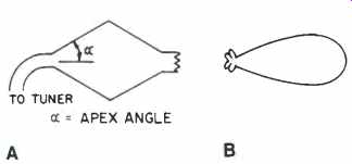
Fig. 1--A-Rhombic antenna, and B, its sensitivity pattern.
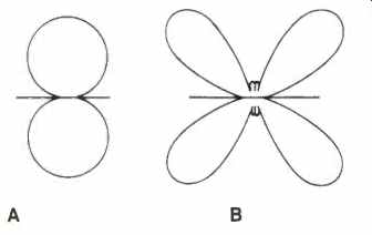
Fig. 2--A-Half-wave antenna sensitivity pattern, and B, full-wave antenna
sensitivity pattern.
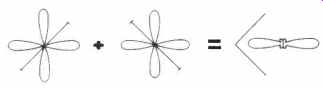
Fig. 3-Combining two long antennas for a vee.
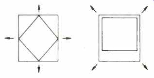
Fig. 4-Installing a rhombic in a room when the signal is in the direction
of one of the arrows.
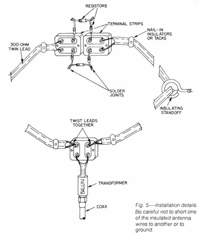
Fig. 5-Installation details.
Be careful not to short one of the insulated antenna wires to another or to ground.
AN AD HOC RHOMBIC ANTENNA
There are two ways to fit a rhombic antenna into a rectilinear room, inscribe the rhombus as in Fig. 4A or overlay a square portion of the room as in Fig. 4B which method you use depends on the direction to the transmitter. Use a map to determine the direction in relation to the room even if you are confident of the right direction. I once installed an antenna before looking at a map; after reinstallation, reception was much better. An alternative is to check the direction in which the rooftop antennas in your area point.
Following this procedure will result in an antenna whose dimensions give good results. Eight feet is about the shortest leg length that is likely to be usable. (The wavelength of 88 MHz is 11.1 feet; 108 MHz is about 9 feet. A leg length of slightly less than one wavelength will work, though not as well as one wavelength or greater.) It is a fortuitous coincidence, but residential room dimensions fall in a range that gives suitable leg length and apex angles.
Antennas built following this design procedure have given good results in Manhattan, where multipath distortion had made stereo reception of several stations too noisy to be listenable when using either a folded dipole or a rabbit ear antenna. Not only did reception improve on these stations, but many low powered transmitters in the metropolitan area, whose existence was hitherto unsuspected, can now be received. The results are impressive, especially considering that these antennas are inside steel frame buildings.
Camarillo, California, is 50 miles from downtown Los Angeles. Between them is a mountain range 1,800 feet high.
Multipath is not a problem; signal strength is. A square rhombic with a leg length of 18 feet has been installed in the living room of a wood-frame house in Camarillo. The wire is stapled to the wall near the ceiling and is barely visible.
Even though the ceiling is tilted, so that the antenna is not in a horizontal plane, reception is much better than with a folded dipole. A log-periodic TV-FM antenna doesn't do as well, even though roof mounted. High-fidelity mono reception of L.A. stations wasn't possible with a dipole. With the rhombic, stereo is undistorted and noise-free.
A square rhombic with a leg length of 11 feet will show a gain of approximately 6 dB or more over a half-wave dipole throughout the FM band. (This is about 8 dB over isotropic.) This is as good as or better than any commercially available FM antenna I am aware of, with the exception of some large, expensive deep fringe models. Smaller rhombics will have less gain, big ones more. This figure includes a 3-dB allowance for signal loss in the antenna due to its length and the thin wire used. The actual signal loss is probably somewhat less than this, yielding slightly higher gain.
CONSTRUCTION
The rhombic antenna's impedance is nominally between 600 and 800 ohms.
Although a non-resonant rhombic is relatively insensitive to impedance mismatch at the feedline, this is too far from 300 ohms to work well with standard twin lead. Standard impedance-matching techniques would limit the bandwidth.
Running two antennas in parallel provides a good match to 300-ohm line; the easiest way to do this is to use twin lead.
Two sets of terminating resistors will be required. The value of these resistors has been arbitrarily chosen as 660 ohms; the exact value is not critical.
(Changing the value of the resistors has the effect of steering the minor lobes in back of the antenna. Experimenting with the value of the resistors will make it possible to tune out a source of interference behind the antenna. I have never yet found this to be necessary.) Noninductive carbon or metal film resistors, 1/4 watt, are suitable, but the capacitance of a single resistor is too high. Use two or, better, three resistors in series to total 660 ohms.
The other materials required will be tacks or staples, possibly insulated standoffs, and terminal strips. The resistors should be soldered together unless extra terminal strips are used. There is a great deal of flexibility in construction.
Use whatever techniques and materials work for you. Take care not to twist the twin lead that forms the antenna. Figure 5 shows my construction details. About the only thing to watch out for is shorting between antenna wires or to ground.
The higher the antenna, the better. An exception is in steel frame buildings. When a ceiling is of steel, the antenna works better if it is at least a foot lower.
In a city, shielded coaxial cable makes the best lead-in wire since it is least sensitive to interfering signals. Use a balun transformer to match the antenna to 75-ohm coaxial cable. Another balun will be needed at your receiver if it does not have a 75-ohm input; 300-ohm twin lead can be used if interference is not a problem. In fringe reception areas, twin lead will give a stronger signal since it has a lower signal loss. To prevent unbalanced currents on the shielding from causing interference, when using coax, coil the cable for two or three turns, about 3 inches in diameter, near the receiver.
The perfectionist will not be satisfied with an antenna that gives merely acceptably good results. There will also be cases when a better antenna than the ad hoc model is needed; deep fringe reception will require greater sensitivity, and severe multipath problems will need a sharper area of sensitivity (better front-to side ratio) than an ad hoc rhombic is likely to provide in such a location. Determining the optimum apex angle for the leg length chosen will realize the rhombic's full potential.
Figure 6 is a graph relating apex angle to leg length in wavelengths. As the leg length increases, the apex angle gets smaller. The frequency range from 88 to 108 MHz includes wavelengths of 9 to 11.1 feet. Consequently, an 18-foot leg length is 1.8 wavelengths at 88 MHz and 2 wavelengths at 108. Which wavelength should be used in designing the antenna? Under most conditions, the longer one. So, for an 18-foot leg length, the apex angle should equal 38°. Actually, the range of angles in this example is 35° to 38°, which is not terribly significant.
Part of the reason for favoring the longer wavelength is evident in Fig. 7.
As the leg length increases, so does gain. Too great an apex angle will decrease gain at the higher frequencies, but the greater leg length in terms of wavelength increases the gain. The effects tend to cancel out.
The formula, 980 divided by frequency in MHz equals wavelength in feet, can be used to calculate wavelength if there is a station or a frequency of interest.
The most practical method of designing an antenna for a particular space is to lay out a scale drawing on graph paper. A ruler and a protractor are the only tools needed. Use successive approximations to find the largest antenna that will fit. A table of trigonometric functions, or a scientific calculator, will speed up the process but aren't absolutely necessary for this.
Fig. 5--Installation details.
Be careful not to short one of the insulated antenna wires to another or to ground.
OUTDOOR CONSTRUCTION TECHNIQUES
The reader interested in constructing a large outdoor rhombic should read the section on wire antenna construction in The ARRL Antenna Book. Smaller antennas (leg length under 30 feet) do not require special construction techniques.
An outdoor antenna should be mounted at least one wavelength high, the higher the better, and should be well clear of power lines. Enamel-coated or plastic-insulated wire is preferable to bare wire. Soft-drawn copper has a tendency to sag. With thin wire, up to 30 feet between supports, or with TV twin lead, sag should be no problem. Hard drawn copper or copper-clad steel should be used for longer spans.
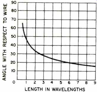
Fig. 6-Angle with respect to wire axis at which sensitivity of the rhombic
is maximum.
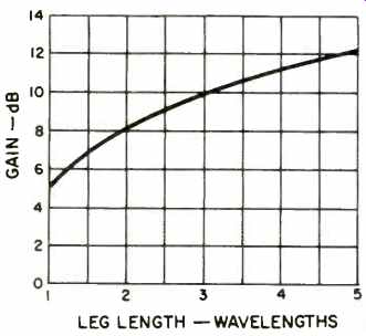
Fig. 7-Theoretical gain of a non-resonant rhombic antenna over a half-wave
dipole in free space. This curve allows 3 dB for loss.
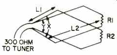
Fig. 8-Double parallelogram rhombic designed for 88 MHz. The wires are in
the same horizontal plane with the crossing points insulated. L1=4.3 wavelengths
48.3 feet; L2=7.5 wavelengths 83 feet; X=52.2 degrees; Y 37.7 degrees; R1-R2
660 ohms, and the gain 27 dB.
Glass or porcelain antenna insulators should be used at the antenna's corners.
Twin-lead stand-off insulators are also possible. The resistors should be protected from the weather; enclosing them in a plastic box, sealing them in silicone bathtub sealer, or spraying them with acrylic lacquer are all possibilities. Lightning arresters should be used. Where wires are joined, they should be soldered or fastened with screws. The sides of buildings and poles are good supports, but trees tend to sway in the wind and the stress can break wire. A pulley and counterweight can provide strain relief if you must use any but the sturdiest tree.
If you're working with a length of wire more than 50-feet long, keep it grounded until you're done working on it. Long wires can pick up enough static charge to knock one unconscious. This was well-known in the early days of radio but seems to be largely forgotten.
AN IMPROVED RHOMBIC
An improved version of the rhombic has been developed by E. A. LaPort and A. C. Veldhuis. A descriptive name for their antenna would be a "double parallelogram." The antenna in Fig. 8 was originally designed by Mike Staal from their specifications for use on 144 MHz.
Gain is estimated to be 27 dB; the theoretical Standing Wave Ratio (SWR) into 300-ohm line is 1 .3 to 1, with little variation over a frequency range much wider than the FM band. (An SWR of under 2 is very good.) Antennas of this design have been used to bounce signals off the moon; I have adjusted the scale for FM use. The required real estate will only be available in the country, which is where high gain will be required. This may be the ultimate VHF deep-fringe antenna. The beamwidth is only 8.5°, so extreme care is required in aiming the antenna. This design is too large to be practical, but one can design smaller antennas of this type. Gain will be lower, but still higher than for a simple rhombic that would fit in the same space.
The double parallelogram antenna in Fig. 8 has legs of two different lengths.
L1 is 4.3 wavelengths; L2 is 7.5 wavelengths. The leg lengths can be changed, and the apex angles adjusted accordingly. The two apex angles, Y X and Y Y, can be found from the graph in Fig. 6. Shorter leg lengths increase the beamwidth. Gain can be found using FM Fig. 7; the gain for a leg length of L1 is added to that for L2. The figure so obtained will be too high when the leg lengths are nearly the same. The design is worth the extra calculation required where multipath problems are severe or signals are very weak.
A double parallelogram is really two rhombics combined. The trick to designing a very efficient one is to have the nulls in one rhombic's pattern overlay the minor lobes in the others, while both major lobes coincide. I've written a short computer program in BASIC to calculate the angles of nulls and lobes and will send a copy to anyone who sends a stamped, self-addressed envelope and $1 for handling to RK Systems, 482 Broome St., New York, N.Y. 10013.
I have built an indoor "double parallelogram" rhombic with L113 feet, L2=16.3 feet, X-90° and Y-60°. The design is a compromise for convenience of construction. The apex angles are not perfect for the leg lengths. Still, performance is better than an ad hoc rhombic in the same location, as multi path distortion is measurably lower. The gain, in comparison to a reference dipole, is between 8 and 9 dB across the FM band. In free space, the figure would be better, but the directivity pattern is distorted by the building's steel frame.
An ad hoc rhombic in the same location had a gain of 6 dB. The antenna was made of white plastic-coated "bell wire" from a hardware store; otherwise, construction was similar to the ad hoc rhombic. The finished antenna is nearly invisible. Many more stations can be received than with a wire dipole, and sound quality is much improved on all stations.
I have been experimenting with indoor rhombics for about a year and am convinced that this is the most cost effective option for serious FM listeners, and perhaps the only option for most Manhattanites.
REFERENCES
1. The ARRL Antenna Book, 1974, The American Radio Relay League, Inc., Newington, Conn. 06111.
2. Laport and Veldhuis, "Improved Antennas of the Rhombic Class," RCA Review, March, 1960.
(adapted from Audio magazine, Jan 1982)
= = = =
Also see: