
By Leonard Feldman and R. Aryana
[Leonard Feldman is a Senior Editor of this magazine. R. Aryana is Chief Engineer of Advanced Audio Systems International in San Jose, California. Portions of this article have been adapted from "A Dynamic Noise Reduction System," an article by Mr. Feldman which originally appeared in the October 1981 issue of Radio-Electronics. ]
Companding noise-reduction systems, such as Dolby and dbx, may be the best-known noise reducers, but they're not the only ones. There is another type, referred to as non-complementary or single-ended, with unique advantages of its own.
In companding NR systems, the signal must be encoded before transmission or recording, and decoded in reception or playback. These systems can reduce the amount of noise a signal picks up within the encode/decode loop, but they can't reduce noise already present in the signal.
Companding NR systems (including Dolby B and C, dbx, and the one described by John Roberts elsewhere in this issue) have the most powerful noise-reduction ability, but they must trade power for compatibility. For instance, Dolby B-encoded tapes are compatible with systems lacking Dolby decoders-you need only turn the treble down to listen pleasurably-but this is the least powerful of the popular companding systems, with only 10 dB of noise reduction. Dolby C NR, with 20 dB of noise reduction, produces tapes which can be listened to reasonably well on systems equipped with Dolby B decoders, but it is barely listenable on systems without Dolby B (again, with the treble turned down in each case). Tapes made with dbx encoding are the least compatible--they're unlistenable on systems without dbx decoders--but provide the most noise reduction (35 dB or more). Single-ended NR systems work in playback only, requiring no special encoding of the signal. While they cannot prevent noise pickup like the companding types, they can reduce noise already present in the signal. And they can be used with any program source: AM, FM, tape, disc, VCR audio tracks, telephone, or even such nonaudio applications as medical electronics and data transmission.


Perhaps the best-known of these systems is the Dynamic Noise Filter, developed by Richard Burwen. A single-chip noise-reduction system based on Burwen's, called DNR, is manufactured by National Semiconductor (See "National's New Noise-Reduction Chip" by Ralph Hodges, Audio, November 1981.)
How DNR Works
The National Semiconductor noise reduction system can provide up to 14 dB of noise reduction in stereo program material and is based upon two principles. The first of those states that noise output is proportional to system bandwidth. Suppose system noise is caused solely by resistive noise (noise added by the circuit resistors). In such a system, noise amplitude is uniform over the system's frequency bandwidth. Thus, if ill the bandwidth of the system is reduced, the noise content is also reduced.
Unfortunately, there isn't a simple correlation between the amplitude of the noise signal and the amplitude of the noise perceived by the listener. As shown in Fig. 1, the ear is most sensitive to noise in the 600 Hz to 6 kHz frequency range. For this reason, when measuring noise content in a system, a weighting filter is usually inserted in the measuring instrument to give better correlation between the measured signal-to-noise ratio and the subjective impression of noise. When a CCIR/ ARM weighting filter (commonly used when measuring signal-to-noise ratios of cassette tape and decks) is used, it will yield noise-reduction numbers of between 14 and 18 dB when the bandwidth of a system is restricted to 1 kHz with single-pole and two-pole low-pass filters, as shown in the curves of Fig. 2.
Auditory Noise Masking
The second basic principle behind DNR is masking-that hearing one sound decreases our ability to hear another. For example, white noise (random noise containing all the audible frequencies at equal amplitude) raises the threshold of hearing a pure tone by an amount that depends on the frequency of that tone, as shown in Fig. 3.
The curve shows a general trend. At a higher frequency, a tone has to be increased in amplitude (compared to a 1-kHz tone) to be heard. That is because a wider range of noise frequencies contributes to masking as the tone's frequency increases. But regardless of the tone's frequency, there will be some range of noise frequencies that will be capable of masking that tone.
The results are not quite the same when we measure the ability of a single tone to mask undesired noise. Experimental results show that extremely high sound pressure levels of a single tone are required to provide masking.
Even at the most effective frequencies (between 700 Hz and 1 kHz, near the natural resonance of the ear), sound pressure levels in excess of 75 dB are required to mask noise at a very low 16 dB SPL. Fortunately, those results apply only to pure single tones.
With the complex signals that are a characteristic of music and speech, masking effects are much better. Most musical instruments produce broadband spectral components and a high concentration of energy around 1 kHz, which improve the noise-masking ability by more than 30 dB over a pure, 1-kHz tone.
From all of that, the designers at National Semiconductor concluded that if source material is at least 29 dB above the "noise floor," adequate masking can usually be obtained.
Therefore, any noise-reduction system that dynamically restricts audio bandwidth will (by virtue of its previously calculated 14-dB improvement) insure a minimum perceived signal-to-noise ratio of 43 dB (29 dB + 14 dB) without audibly degrading the music program.
A cassette tape recorded at a mean signal level of around-10 VU (volume units, as on a VU meter) -40 to 45 dB above the noise floor of the tape/system-will, with the aid of a bandwidth varying noise-reduction system, be improved to a perceived signal-to-noise level of between 55 and 60 dB. If the recording was made at 0 VU, the improvement can be expected to provide an S/N ratio of better than 65 dB.

Fig. 1--The ear's sensitivity to noise varies with frequency.

Fig. 2--How decreasing bandwidth affects noise reduction, with DNR configured
as a single-pole (curve a) or double-pole (curve b) low-pass filter.

Fig. 3--Hearing thresholds above white noise for pure tone.
The DNR Audio Filters and Control Path
The general arrangement of the DNR system is shown in the block diagram of Fig. 4. Two low-pass filters (one for each stereo channel) are placed in the audio-signal path, their-3 dB bandwidths controlled by the amplitude and frequency of the incoming signals.
Each filter response is flat below its cutoff frequency, with a smooth, single-pole roll-off above its corner frequency for any control setting. The resulting-6 dB/octave slope produces the most satisfactory results with modern and classical music having a wide frequency range. Steeper slopes can produce greater amounts of noise reduction for a given bandwidth, but are more suited to program material that does not have substantial high-frequency content. Cascading two filters will give a -12 dB/octave slope, with noise reduction as great as 18 dB (see Fig. 2).
As Fig. 4 shows, the LM1894 has three signal paths-right- and left channel audio signal paths and a common bandwidth-control path. The main paths include audio low-pass filters whose cutoff frequencies vary in accordance with the control signal. A single control signal is used for both channels to keep the stereo image from wandering. That signal, in turn, is derived from the output of the summing amplifier, which is then filtered and rectified.
Since the spectra of musical instruments and the ear-sensitivity curve (Fig. 1) imply that masking is most effective at relatively low frequencies, you might assume that a low-pass filter would be good for the control path shown in Fig. 4. However, that turns out not to be the case. Figure 5 shows the frequency versus amplitude response of the DNR IC control path. The DNR system uses a high-pass filter with a -3 dB corner frequency of 6 kHz and -12 dB/octave roll-off slope. An optional notch at 19 kHz is for when the source material contains a stereo-FM pilot signal that might tend to increase minimum bandwidth above 800 Hz when the detector threshold is set at the noise floor.
The control-path frequency response is weighted in that manner because program material varies substantially in harmonic content, depending both on relative loudness and on the particular instruments being played. As an example, consider the case of a French horn. Most of the energy produced by that instrument is below 1 kHz. If a low-pass filter were used in the control path, it would respond to that energy and open up the filters to full bandwidth, unmasking noise in the 2-kHz and above region.
To avoid that, the system looks for high-frequency energy in the music source, and, not finding any higher harmonics, in the case of the French horn, the noise remains filtered out and bandwidth remains restricted. Multiple instruments or a solo instrument such as a violin, for example, may have significant high-frequency energy that will not only provide good noise masking but will require a wider system bandwidth. To summarize, then, the detection of high frequencies in the system's control path indicates that large levels of energy must be present in the critical masking-frequency range. This means that the audio bandwidth can be safely increased to prevent audible degradation of the music, since the noise will remain masked. To make up for the relatively fast decrease in spectral energy with increasing frequency, the control-path response is increased at a 12 dB/octave rate.
Attack and Decay Times
If the detector of the DNR system were allowed to respond instantaneously to any input signal, ticks or noise bursts (of short duration but with rapid rise-times) would be able to open up the bandwidth of the system without simultaneous program masking. Also, different instruments have widely differing rise-time characteristics. With that in mind, the DNR system was designed with an attack time of 0.5 mS to minimize potential loss of high-frequency transients. That does constitute a trade-off in that the system is susceptible to impulse-noise interference. Impulse noise, having fast rise and decay times and quite a bit of high-frequency energy, must be eliminated using other techniques.
Once the detector has responded to a given musical transient, it must decay back to its inactive level when that transient is over. Once again, a compromise in parameters was required for the DNR system. Too slow a decay time would mean that system bandwidth would remain "wide open" for some period after the decay of the transient. A noise burst would be heard at the end of each musical transient since there would be nothing to mask it. If the decay was too rapid, on the other hand, a loss in apparent ambience would occur because harmonics occurring at the end of a transient would be suppressed. The DNR system decays to within 10% of final value in 50 mS. The ear's inability to recover sensitivity for 100 to 150 mS following a loud sound prevents the noise burst that is present at the end of each transient from being heard.

Fig. 4--Block diagram of the DNR system.
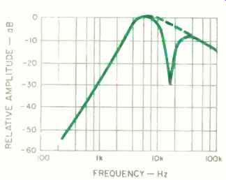
Fig. 5--Response curve for the DNR control path. Notch at 19 kHz is optional,
to diminish response to FM pilot tone.

Fig. 6--Schematic of the DNR system, main section.
Using the DNR System
The DNR system is designed to be placed before a system's tone and volume controls. This is because any adjustment of these controls would alter the noise floor seen by the DNR control path. A sensitivity-adjustment pot is provided, which may need to be adjusted for the noise floors of different sources (e.g., tape, FM or phono). This control should therefore be left readily accessible.
The system incorporates a display to assist in the proper setting of the sensitivity control. The display shows the instantaneous bandwidth of the two filters, not signal level (though signal level does affect it indirectly), and is logarithmic to best indicate the filters' audible effects. A bar-graph display is used instead of a meter because of the control signal's millisecond response time. The LM3915 display is recommended, as it requires only a few external parts and contains all the necessary circuitry for a 10-point, logarithmic display.
The left-hand LED corresponds to an 800-Hz bandwidth; the right-hand LED corresponds to a 30-kHz cutoff. The LEDs between these extremes each represent steps of approximately 1.5 times the frequency represented by the preceding step.
Using the Filter
The DNR unit can now be connected in the tape monitor loop of a receiver or amplifier. The sensitivity control should be turned down completely, and source material should be chosen that does not have musical content (the groove between cuts on a record, for instance).

Fig. 7--Schematic of the display section.

Fig. 8--Schematic of the power supply.
Under these conditions, all but the first LED should be off. The sensitivity control is then advanced until the next LED just begins to flicker. This is an indication that the filter is barely opening on the noise floor and is capable of reaching full bandwidth on musical information above this level. Alternatively, the control may be advanced until there is a barely perceptible increase in the noise level and then backed off very slightly.
The bypass switch can be toggled between the bypass and active positions to compare the action of DNR with that of a full system response. The difference should be quite dramatic, giving a subjective improvement in S/N of 12 to 14 dB. The action of the filter is most apparent between record cuts, where it removes nearly all of the annoying hiss.
You should be aware of a psycho acoustic effect that is common to all noise-reduction systems. The addition of high-frequency noise (such as tape hiss) to a music signal will seem to increase the high-frequency content of the music. Thus, upon first auditioning DNR using noisy source material, the user will seem to hear a degradation of the music's high-frequency content.
The system's actual effect on the high frequency information can be observed by using a quiet source and switching the filter in and out.
It should be noted that the filter is designed for an average input level of 750 mV rms. Some tape decks are capable of much larger output levels at "0 VU," and they should be attenuated accordingly to prevent overloading the filter inputs.
Building the DNR System
Construction is fairly simple, as the bulk of the circuitry is on two ICs, the LM1894N DNR chip and the LM3915 display (Figs. 6 and 7), plus a power supply (Fig. 8). The 19-kHz multiplex pilot tone pre sent in all stereo FM broadcasts is attenuated by L1 and C-L. The presence of this pilot tone will limit the noise-reduction capability, since the noise filter will sense the level of the pilot tone rather than the level of the noise source.
The inductor provided with the kit of parts described in the Parts List is pre-tuned, and its adjustment should not be altered. If, however, you purchase coil L1 separately, then it must be tuned to within about ±20 Hz of the 19-kHz pilot tone. The simplest way to obtain this reference frequency is to get it directly from the FM broadcaster.
Tune your FM receiver and wait for a quiet interlude when there is no audio signal. Tune L1 for minimum noise-filter bandwidth as monitored on the front panel's LED display.
Video and TV sound can create similar problems due to the presence of strong line-scan components at 15.734 kHz. This can be accommodated by substituting a capacitor of 0.018 to 0.022 µF for the 0.015-µF value indicated for capacitor C-L, and readjusting L1. If both FM pilot and video line frequencies cause problems, it might be advisable to build two traps, with a selector switch. On the Other hand, if neither FM nor video-sound signals are to be processed, then choke L1, capacitors C-L and C8, and resistor R8 (which forms a frequency roll-off with C8) may be eliminated.
Printed circuit boards, silk-screened to show component placement and polarity, are available separately or as part of a complete parts kit. All components are mounted on these boards, except for the sensitivity control, switches, jacks, the power transformer and the fuse-holder. We recommend using IC sockets or Molex strips instead of soldering ICs in directly, to prevent possible damage to the ICs.
The component designations on the p.c. board and their explanation in the Parts List should provide all the information needed for successful board assembly. A schematic diagram (Fig. 6) is provided for technicians who feel more comfortable working from that, and / or help in understanding and trouble-shooting the circuit. The display and power-supply circuits are shown in Figs. 7 and 8.
Figure 9 shows how the boards and other components are wired together.
Wire functions and colors are also silkscreened on the boards.
Nonetheless, mistakes are still possible. Our experience has shown that the most common assembly errors are as follows: ICs inserted backward, electrolytics installed with incorrect polarity, power diodes reversed, bad solder connections, no fuse in the fuse holder, and failure to wire-connect one or more phono-jack grounds to a common ground on the p.c. board. But with a little care (or, failing that, a little after the-'act trouble-shooting), you should have an addition to your system that makes a worthwhile, audible difference. Get out your old, pre-Dolby tapes and surface-noisy records, and prepare to listen to there--and enjoy them-once again.

Fig. 9--Assembly diagram, for use with p.c. board.
======================
Parts List
Resistors:
(All 5%, 1/4-watt, except R1.)
R1-1-kilohm miniature pot, audio taper.
R2 through R4, R31-1 kilohm.
R8-100 ohms.
R10, R11-47 kilohms.
R32-430 ohms.
R33-910 ohms.
Capacitors:
C1, C5, C8, C22-0.1-µF, 50-V Mylar.
C2, C4, C10, C11, C13-1-1.1,F, 50-V electrolytic.
C3, C12-0.0033 µF, 50-V polystyrene, axial-lead.
C6-0.001-µF, 50-V Mylar.
C9-0.047-µF, 50-V Mylar.
C14-100-µF, 50-V electrolytic.
C15-10-1.1F, 16-V electrolytic.
C16-470-µF, 25-V electrolytic.
C-L-0.015-µF, 50-V Mylar.
Semiconductors:
D1 through D4-1N4002 diodes.
IC2-LM1894N DNR. IC3-LM341T-12 or LM78M12 regulator.
IC4-LM3915N display driver.
IC5-G L 112-R 13 12-element play.
Miscellaneous:
SW1, SW2-SPST rocker switches.
L1-4.7-mH adjustable inductor, 0=35 at 19 kHz (Toko CLN20740HM).
PH1, PH2-Dual phono jacks.
Transformer -- 14.5-V, 250-mA, center-tapped (Triad F-112X). Fuse-1/4-amp, slo-blow.
Fuse-holder, line cord, p.c. boards, control knob, and miscellaneous hardware.
The following are available from Advanced Audio Systems International, 4010 Moorpark Ave., Suite 105, San Jose, Cal. 95117. ( California residents, add 4.5% tax.)
Complete kit, including silk-screened enclosure (DNR-200X) $122.50
Listed semiconductors and coil L1 (DNR-240X) $35.95
Main and display p.c. boards (DNR-280X) $22.50
========================(adapted from Audio magazine, Feb. 1985)
= = = =
Also see: Build a High-Performance Noise Reducer (Feb. 1985)