In the August, 1976, issue of Audio I gave a brief description of the new Ampex ATR-100 tape recorder which was introduced at the 54th AES convention in Los Angeles. I promised that when I got a chance to play with one of these recorders, I'd do an in-depth report on it.

Well, friends, I've been living with an ATR-100 for some months now, and-to
put it simply-the ATR-100 is a new breed of tape recorder, unlike any other
machine, displaying technological advances in a number of areas which show
an ultra-sophisticated conception of the tape recording art.
Modular construction has been a feature of recent Ampex recorders, and the ATR-100 carries this concept still further. Not only is there the basic modular system for tape transport, head assembly, control unit, electronics assembly, and power supply, but the tape transport is further divided into sub-assemblies. All are electrically interconnected with polarized wiring harness plugs. As is usual with Ampex tape recorders, the tape transport is built around an extremely rigid, precision-machined, cast aluminum base. The capstan, supply, and take-up motors; constant tension supply and take-up arms, and tape-timer wheel assembly are all mounted to the base, which also serves as a transistor heat sink for the power supply.
As I noted in my initial description of the ATR-100, the tape transport is a closed-loop servo system, which maintains constant tension between supply and take-up reels and neither needs nor uses a pinch roller! Let's follow the tape path...From the supply reel, the tape passes around the constant-tension supply aim, which is equipped with a metal roller and ceramic tape guides. (These roller/guide assemblies are easily and quickly changed with a single screw and are available for either quarter- or half- inch tape.) Tension arm position is sensed by a photo-resistive element and activated by an LED attached to the arm. It isn't indicated, but I presume a cadmium sulfide cell is used, as it would have the requisite sensitivity for the low output level of the LED. Voltage output is proportional to the arm position, and any positional errors are corrected by commands to vary the torque of the supply reel servo motor. Tape then passes around a knurled, large diameter (2 1/2 in.) tape timer wheel, which has an optical tachometer whose output appears on the digital time readout on the control panel. The tape path continues through the headblock, around the capstan, which is also knurled and the same diameter as the tape timer wheel. The capstan speed is servo controlled. A solid-state optical device reads a 1200-line tachometer disc on the capstan shaft, and this signal is compared with the reference signal from a master crystal oscillator. Special circuits make appropriate corrections for any speed anomalies. The capstan servo has two modes of operation. One is a phase-lock constant velocity mode used for play and record; the other is a controlled acceleration mode for fast-forward and rewind, as well as start and stop. Complex circuitry automatically controls switching from one mode to the other. Thus, the capstan is independently driven, and all controls of tape motion is by the capstan controlling the reels.
The capstan and the reel servos are mechanically linked by the tape and are electrically linked as well. From the capstan, the tape passes around the constant-tension take-up arm and roller/guide on the right side of the deck. This arm, of course, functions in the same manner as the supply arm.
This completes the closed-loop servo system.
Tape Motion
With this system, drive to the reel motors is bi-directional...the reels are capable of feeding tape with as much force as they are of holding back tape.
All control of the servo system is by 5 volt TTL (transistor/transistor logic). With this logic and the servo system, constant tension can be maintained on each side of the capstan. This results in superb tape handling, very smooth and gentle, with no danger of inaccurate tape timing through tape elongation. The ATR-100 can handle any size reel from 2 to 14 inches with a total disregard of tension problems which would ordinarily arise with such disparities in reel size. While I haven't tried this, I understand the ATR-100 constant-tension system is so precise and gentle that reels of flimsy cassette tape can be handled without any problems...even in fast-forward and rewind modes! The ATR-100 is also very easy to thread. When the machine is turned on, the constant tension supply and take-up arms are not activated. Threading the tape into the closed loop, the Stop button is depressed and held, and the supply reel given a little "jiggle" to simulate holdback tension. The constant tension arms then pull-in and lock, activating the reel servos, and the recorder is then in operating mode.
The ATR-100 can operate at 3 3/4, 7 1/2, 15, or 30 ips, and any two speeds can be selected at one time, even something as incongruous as 3 3/4 and 30 ips. Equalization and bias are automatically switched for the two speeds chosen on the tape transport speed switch. If you select the wrong speeds on the switch, a red "lockout" light glows next to the speed, and the transport won't operate. If you want o change to another speed pair, linking plugs on the audio control board must be transported to another position...again changing equalization and bias. In fast-forward and rewind modes, the ATR-100 can strip a 2400 ft. reel of tape in less than 60 seconds.
There are no mechanical brakes on his recorder...braking is completely dynamic and very positive. While ripping tape off at 500 ips, depressing the play button slows the tape rapidly; the machine does not stop but rather locks smoothly into the Play mode peed. As you probably know, professionals like to wind off their tapes in the "tail out" position. This takes time, especially if you have only 1000 feet of program on a 2400-ft. reel. To facilitate this, the ATR-100 has two pooling speeds, which can wind tape t either 80 or 160 ips. Even at 160 ips, with back-coated tape, the wind is so smooth it looks like brand-new tape.
Headblock Features
Underneath the pull-off head cover s the headblock which is completely removable. The head block is very solidly constructed, and the underside as three well-machined locating pins which mate with another precision machined area on the transport casting. There is heavily spring-loaded-bar that, with a 90 degree turn of an Allen wrench, locks the head block securely to the machined plate. Electrical connection is by means of PC board edge "finger" connectors, which mate with a mother board. The headblock is fitted with an upper and two lower ceramic tape guides, a crape flutter filter, and either full track, half-track or stereo, erase, record and reproduce ferrite heads for quarter-inch tape, or with the same complement of ferrite heads with four channels for half-inch tape.

There is space for a fourth head, and if not fitted, there is a dummy head metal post. Automatic solenoid-operated tape lifters come up into the headblock from the transport top plate. A spring-loaded, press on and off headgate shields against hum. The use of ferrite heads by Ampex might raise a few eyebrows because of some of the well-known problems associated with this kind of heads. (For example, ferrite is easily saturated; it is a friable material which chips easily, and when this happens in the gap, it causes gap scatter. On the other hand, extreme hardness cuts head wear drastically, compared to permalloy, and its composition permits high bias frequencies.) The Ampex ferrite heads are very special. They are literally "grown" and thus are known as monocrystalline ferrite. They retain the advantages of hardness for long wear, and their suitability for high bias frequencies is indicated by the ATR-100's bias of 432 kHz. With single crystal structure, saturation is not a problem.

Extended high frequency response is another virtue of these heads. Most fascinating of all is that the gaps of these heads in multi-track configuration can be aligned with such precision, that when used with a special record circuit, they are phase coherent and can record square waves! Before we leave the head block, it should be noted that the record and replay heads are precision mounted and require no adjustment for height or zenith.
Azimuth is adjusted with an Allen wrench turning a gear-toothed wheel underneath the heads.
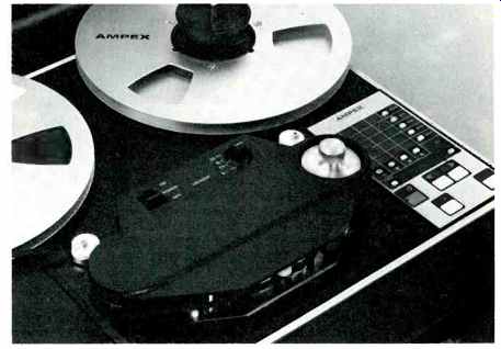
The control panel on the ATR-100 is really unique. Except for the power switch and tape speed selector which are on the headblock cover, the panel contains all other function controls.
There are pushbuttons for Play, Record, Stop, Fast-Forward, and Rewind. On a computer/calculator type panel are buttons for Safe, Ready, Sel Sync, Repro, and Input arrayed vertically on the right side of the unit. In horizontal array underneath are buttons numbered one through four; any of which can be punched up to any or all of the four channels of control. The mode selected is indicated by vari-colored LEDS. The electronic timer is extremely accurate, within 0.5 second for a 2400-ft. reel of tape. On the control panel hours, minutes, and seconds are shown in an illuminated digital readout. Now get this editing routine...the capstan protrudes through the headblock cover and has a knurled knob on top of it. With the tape stopped, but with the constant tension arms in servo lock, you can turn the capstan manually for editing, with a smoothness and precision of cut point that has to be experienced to be believed. Then, if you want to spill tape, the Edit button on the control panel puts the recorder into the Dump Edit mode. The take-up motor stops, and the right tension arm roller moves a thin rubber tire, which acts as a pinch roller on the capstan to spill the tape. Ingenious! The control panel also is available in a remote control version with 25-ft. cable, and this duplicates all functions except the Dump Edit mode. While the ATR-100 is normally shipped with the control unit on the right side of the transport, it can be easily installed on the left side for those engineers who are southpaws.
I was supplied the four-channel, half-inch version of the ATR-100 (with interchangeable stereo head and tape guides as well) in the pedestal/cabinet configuration. In this set-up, the electronics package is mounted underneath the transport, behind a hinged cover. All electronics are on what Ampex calls "printed wiring assemblies" (PWA). We call them printed circuit boards, and like most of them, the Ampex PWA plug into a motherboard. There are four main audio boards, each with what is called a "padnet" (parameter determining network) which plugs into the PWA boards. Then there are the audio control PWA, transport logic and tape timer PWA, capstan servo PWA, and reel servo PWA, with many controls to explain on these boards. Next month I'll get to these, plus the input/output modules (levels, metering, etc.) plus the results of the extensive measurements of performance parameters, plus listening tests and a subjective evaluation.
(Source: Audio magazine, March 1977; Bert Whyte)
= = = =