Many attempts were made before the year 1928 to provide talking motion pictures for general theater use. The inability to provide recording and reproducing equipment on a practical commercial scale resulted from limitations in microphones, amplifiers, loudspeakers, disc and film techniques, and the lack of general research needed to provide tools for their commercial application.

Col. Nathan Levinson, the Pacific Coast representative of the Western Electric Co. for broadcast and public address systems, rented a public address system to Universal Studios used in the production of "The Hunchback of Notre Dame" and by supplying this equipment, he became acquainted with motion picture executives. Levinson was a friend of Ralph Bown, in charge of radio facilities for the Western Electric Co., who told Levinson that Western Electric had experimental talking motion picture equipment ready for a demonstration.
Early in 1926, Levinson talked with MGM, Goldwyn, and others to determine their interest in seeing a demonstration. Sam Warner of Warner Brothers was the only one technically interested in this new development.
His brother was opposed as were other studio executives who believed movies with sound would ruin their business. Sam Warner sneaked Col.
Levinson into the Warner lot by covering him up in a blanket as they passed the guard gate. After several meetings at Warner Studios, the Warners agreed to witness a demonstration at the Bell Telephone Laboratories in the early part of 1926.
The Warner brothers were so enthusiastic over the preliminary tests that they arranged for full scale tests using their own cameramen, artists, and technicians in cooperation with the Bell Laboratories staff. After several tests, the Warner Brothers were convinced that a corporation should be organized to produce and market sound motion pictures and equipment. A short subject with Bryan Foy was then made in the Manhattan Opera House in New York City. George Groves was the mixer, and he relates that many times recording was stopped due to subway noise. The first theater sound equipment was transported and installed with armed guards because of the mistaken fear by producers and exhibitors that sound was not compatible with motion pictures, and equipment sabotage was possible.
In April of 1926, the Vitaphone Corp. was organized with "Sam" L. Warner as president, and the first major Vitaphone sound picture was "Don Juan" released in August, 1926, in which music from the New York Philharmonic was featured. Plans for production in Hollywood were immediately started, and sound stages were built using the recommendations of the best acoustical experts. "The Jazz Singer" with Al Jolson was placed in production in April of 1927 and exhibited in New York City on October 6, 1927. It was so successful that almost every motion picture producer was convinced sound motion pictures were here on a real basis. The Vita phone equipment consisted of a synchronized 33 1/3 rpm, 16 in. disc, a turntable geared to the projector using a Western Electric 4-A pickup, and their amplifiers and loudspeakers.
At this point, it is necessary to review the work of several individuals who were largely responsible for the ability of Western Electric to design, manufacture, and provide the necessary hardware needed for this important step. Edward C. Wente came to the company in 1914, and in 1917 he designed the forerunner of the famous Western 394-W condenser microphone which was produced commercially in 1926. This microphone provided the necessary sensitivity and frequency range to adequately record speech and music with excellent quality. Wente and Thuras also designed a dynamic type driver, the Western Electric 555-W receiver which, when coupled with a horn consisting of a one-in. throat and a 40-square-foot mouth area, was capable of a range of 100-to-5000 Hz and with an average midrange efficiency of 25 percent.
With five watts input, it could create more than one watt of acoustic power. By using multiple driver units and several horns, it was then possible to fill the larger theaters (3000 to 5000 seats) with ample sound power to adequately reproduce speech, sound effects, and music! This efficiency of 25 percent compared to less than one percent on present home high quality cone type speakers was needed because only 2.5 and 10-watt amplifiers were available. These amplifiers used filamentary type vacuum tubes requiring d.c. from batteries or motor generators for both filament and plate supplies. The power amplifiers were of the 205-D type in single ended and push-pull circuits. The recording amplifiers were of the type which were used so successfully in the first 500-watt broadcast transmitters-studios and public address equipment. The 8-A and 9-A amplifiers provided the amplification from the 394-W condenser transmitter amplifier, which fed the recording equipment. A speed of 90 feet per minute and 24 frames per second was chosen for both the sound disc and the sound on film equipment which was released in 1927. Accurate speed was possible due to the work of H.M. Stoller who used a bridge balanced driving motor.
Unbalance of the bridge provided the necessary change of current which increased or decreased the motor speed as required.
In January of 1927, Electrical Research Products, Inc., was formed as a subsidiary of the Western Electric Company to handle commercial relations with the motion picture producers and exhibitors. At this time, both disc and film recording methods were made available. Again, Wente was responsible for another important device, the light valve. This was a string valve using two ribbons suspended in a plane at right angles to a magnetic field. The ribbons were six mils thick and stretched to a resonant point of 8500 Hz. A fixed source of incandescent light illuminated the opening between the ribbons spaced one mil apart. Current from the recording amplifier moved the ribbons from the normal spacing of one mil to either complete closure of the slit or to double width of two mils as a maximum for 100 percent modulation of the fixed source of light. This slit was focused on the film by an optical system with a two-to-one reduction. This is the variable density type of sound recording on film system.
Sound Beginnings
In April of 1928 (six months after the showing of the "Jazz Singer"), Paramount, United Artists, MGM, Universal, and others signed agreements with Electrical Research Products, Inc. (ERPI), for licenses and recording equipment. One can only imagine the intense activity resulting from these contracts. Western Electric utilized all of its telephone plant manufacturing facilities at Kearney, N.J., and the Hawthorne plant in Chicago to produce the required 16 recording channels delivered in late 1928. What hectic days these were! Sound stages were erected with Dr. Vern Knudsen of UCLA serving as acoustical consultant. Sound directors, transmission engineers, and recording staffs were recruited from the broadcast industry, the telephone companies, phonograph recording companies, and any related field since there were few sound experts, and none with talking picture experience. An augmented staff of writers, composers, and stage actors were also assembled. The training of staff kept pace with material developments. The Academy of Motion Picture Arts and Sciences, funded by the eight major producers, gave night school instruction to 900, and this course resulted in the publication in 1931 of the book, "Recording Sound for Motion Pictures," published by McGraw Hill Company. I was privileged to be one of the authors.
Hollywood, the capital of the silent motion picture, now, in its reincarnation, had a voice! Stars of the silent screen recorded their voices, and many failed to qualify for the sound pictures. The success of outdoor pictures, such as " Arizona," shook off the belief that a sound stage was essential.
RCA Photophone, Inc., was organized in 1928 to promote its commercial exploration of their sound on film system. The Photophone group was organized from a three cornered arrangement between General Electric, Westinghouse, and RCA. The Photo phone system of recording used the variable area method. The sound tract is produced by actually moving a light beam of uniform intensity back and forth lengthwise across a slit whose length and width are fixed. The resulting sound track in its early form had the appearance of a serrated or saw tooth edge of uniform density adjoining a uniform transparent area.
Otherwise, all sound recording and reproducing equipment is essentially alike. By the end of 1929, ERPI and RCA had equipped more than 5,000 theaters in the U.S. and 2,000 abroad.
Warner Brothers continued the Vitaphone method of sound on disc up to 1933, at which time they switched to sound on film because of the obvious advantages of synchronization, editing, and standardization with the other studios.
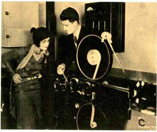
----Douglas Shearer shows his sister, actress Norma Shearer, how the
voice is photographed on film as it comes through the recording channels
in the form of electrical impulses. (Photo-Courtesy of Western Electric.)
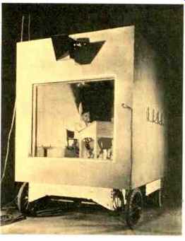
--- Sound recording monitor booth first used in 1928 with John K. Hilliard
at the mixer controls.
Movie Memorabilia
It was my good fortune to have been selected for this work from a group trained in physics, engineering, acoustics, and broadcasting experience. In September of 1928, I arrived at United Artists Studio as transmission engineer in charge of the recording operation. Dr. Vern Knudsen had designed the sound stages which were nearing completion, and recording equipment was arriving from the Western Electric Co. Everyone had more than their share of work to do since our first talking picture, "Coquette," with Mary Pickford and Douglas Fairbanks, was to start in November. Both disc and film equipment were installed in duplicate since at the time of contract signing, it was thought both would be used. Actually, the disc equipment was used for instant playback of the recording, and using the soft wax for this purpose.
The wax was processed into a pressed record and used as a backup in case the film recording was not adequate.
This duplication was dropped after a few pictures since the use of two film machines proved to supply adequate protection.
The experience of Western Electric did not involve a full feature length film, including editing and release printing of the hundreds of prints needed for simultaneous exhibition, so we were immediately faced with the problem of creating "dubbing" facilities. This consisted of providing a number of reproducing sound heads in a re-recording room where a number of recorded films could be synchronized, including music and sound effects along with the original dialogue. A new single negative was then available for the final release. As many as 16 separate sound tracks were used to composite all of the individual sound tracks. The filamentary type vacuum tubes had many problems, and microphonics was the source of greatest agony. All amplifiers near or on moving equipment had to be suspended on shock assemblies. Even acoustic energy such as monitor loudspeakers or high room noise levels were responsible for many retakes. In 1931, I had a conference with M.J. Kelley at the Bell Laboratories to determine when heater type tubes would be available for recording equipment since they were appearing in radio receivers. He provided information on a series of heater type tubes having low noise, long life, and excellent stability.
In 1933, I transferred to MGM studios and began a systematic review and redesign of all recording amplifiers.
The existing amplifiers had been in use from 1925 with little or no revision. We were concerned that the phase shift between the lowest and highest frequencies was on the order of 1500 degrees in the recording channel, which distorted speech and caused a loss of articulation. A large number of transformers were used in the record-g circuit since the amplifiers were in many locations, and each amplifier required an input and output transformer to work on low impedance circuits varying from 30 to 600 ohms. Phase shift is reduced by using transformers having very high self-inductance (5 H per 100 ohms of circuit impedance) and relatively large coupling capacities with extremely low leakage and distributed capacity. When used in recording amplifiers, transformers-designed by E.B. Harrison and manufactured by Lansing Manufacturing Co.-reduced the overall recording channel phase shift to less than 360 degrees (in the recorded frequency range, the phase shift is directly proportional to frequency). When these redesigned recording amplifiers were placed in service, it became very apparent that speech, sound effects, and the attack on sounds of musical instruments were greatly improved in fidelity. The techniques were then applied by others to bring hi-fi amplifiers to the disc recording and home music fields. At the same time, it became obvious that the maximum benefit of improved recording quality must be matched with equal theater reproducing equipment quality.
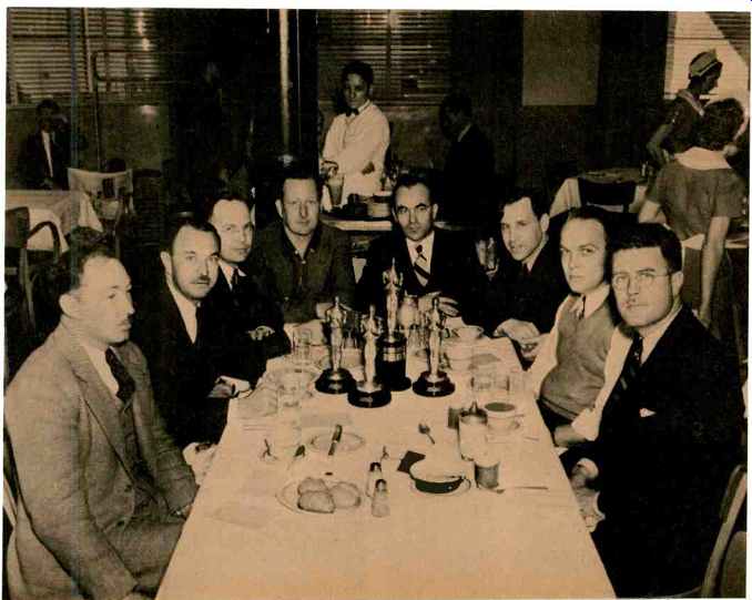
---- Luncheon of the MGM studio sound department staff after receiving
Academy Awards in 1936 for loudspeaker systems and the push-pull variable
density light valve. Douglas Shearer is at the near right side.
Cooperative Problem Solving
The Research Council of the Academy of Motion Pictures Arts and Sciences was organized in 1934 to cooperatively handle technical problems for the industry. A theater standardization committee was appointed for the express purpose of coordinating the sound recording quality within the major studios and provide information on adjustment of theater equipment for a commercially acceptable quality level. Early in the program, a test reel was assembled using a short length of a regular release print from each of the studios. It was used to adjust all studio projection rooms for an optimum frequency response characteristic when reproducing typical pictures of all studios. This test reel proved to be so valuable in Hollywood that prints were made available to service companies, equipment manufacturers, and theaters. By this method, theater equipment was adjusted on a uniform quality basis taking into consideration the acoustics of the auditorium and the loudspeaker characteristics. Power requirements for theaters based on size was next standardized. Finally, a bulletin on theater acoustics was issued indicating the desirable acoustics for new theaters and the methods of modifying existing theaters.
Early in sound motion picture recording, the need for added artificial reverberation became apparent.
Time delay for echoes and added reverberation to music was desirable, but such equipment was not available.
First attempts included using several prints of sound tracks spaced one or more frames apart and delayed from the original track. These were then mixed together with results which fell short of the goal. Another attempt was using a long pipe, 300 to 500 feet in length, driven by a loudspeaker on one end and picked up on microphones at 100 feet intervals and added to the original sound. This gave better results than the spaced tracks, but limited the type of reverberation.
In 1934, the Hammond Electronic Organ had as an accessory a "reverberstat" which supplied artificial reverberation to the organ notes. This unit was composed of a series of coil springs of different lengths and diameters driven by a loudspeaker and the opposite ends of the springs energized the microphones. This was the first method which achieved a desirable added reverberation to original sounds.
One of the early pictures using artificial reverberation was "In May Time" with Jeanette McDonald. A long shot was used to establish her far off entrance, and then the camera dollied in for a "close up." We used various amounts of reverberation to match the varying camera shots. At that time, it was customary for an actress or actor to review all scenes and takes with the film editor and select the best "take." However, they did not see the dubbing in its final form before release to the theater. I went to Grauman's Chinese Theater on the opening day of the performance as usual to adjust the volume by a control placed on a seat near the center of the house. When this scene came on, Jeanette for the first time heard the reverberation and realized that something was changed. After the scene was over, she dashed to my seat and said, "John Hilliard, what have you done to my picture?" Of course, after the shock was over, she realized the improvement, and never again was there any question about adding reverberation where it was needed.
Later, reverberation rooms were built consisting of special rooms with little absorption so that reverberation periods of up to three to five seconds were available. These rooms were energized by a loudspeaker and picked up by one or more microphones. At a later date, drum, disc, and tape delays augmented the supply of sources for artificial reverberation.
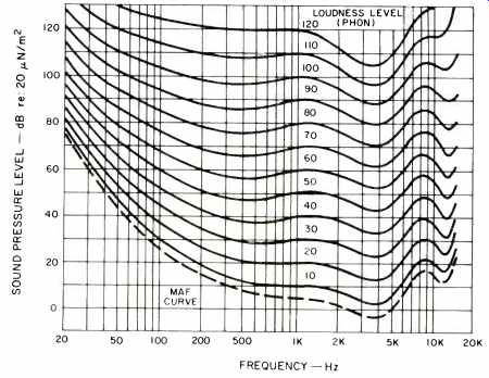
Fig. 1-The Fletcher-Munson curves.
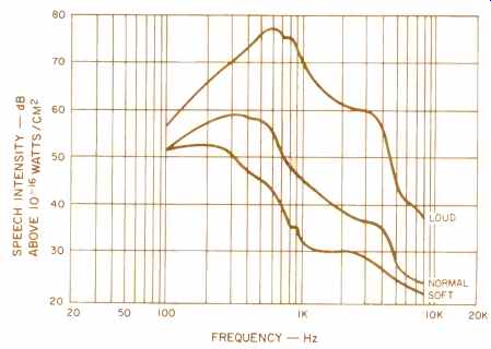
Fig. 2-The average voice characteristics of men and women.
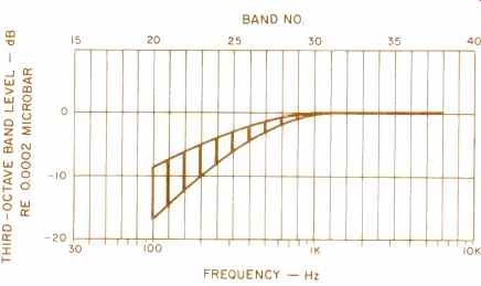
Fig. 3-The minimum and maximum amount of attenuation in the dialogue equalizers.
Music Pre-Scoring
The need to record music with vocal selections became obvious at a very early date in sound motion picture recording. Stage noise caused by the hum of arc lights, cameras, ventilators, improper acoustics, placement of orchestra, and many special handicaps forced the techniques of pre scoring all musical portions of the picture. This was done by placing the orchestra and soloists in a stage designed specifically for music. (The noise levels were below 35 dBA.) The orchestra was picked up by several microphones to obtain the desired balance, and the solo and choral groups used separate microphones.
Up to 1935, only non-directional microphones and the RCA ribbon microphone were used. The soloists were isolated acoustically as much as possible from the orchestra with panels (flats), but it was always necessary to have the soloists hear the orchestra and face the musical director.
An MGM representative stationed in Berlin in 1935 informed the studio in Culver City that the Siemens Co. of Germany had developed a directional microphone (cardioid pattern) so that the back side of the microphone materially suppressed sound pickup.
Thus, the soloist on the front side had full pick-up and the back side suppressed the orchestra. A sample microphone was immediately sent to Culver City and first used on "Naughty Marietta" with Jeannette McDonald and Nelson Eddy. The Siemens microphone was considerably larger than the condenser and dynamic microphones then in use. Since Jeannette McDonald had a very weak voice compared to Nelson Eddy, balance was a big problem. As a result, the directional microphone was first placed in front of Jeannette McDonald. An immediate question from Nelson Eddy was why a new microphone was being used for her. He was told that it had pronounced directional properties so that she could be acoustically isolated for balanced pick-up. Eddy then requested we use the same type microphone on him.
We explained that we only had one such unit. However, he preferred not to record until we had a similar unit for him-an ultimatum. All major studios have "prop shops" that can du plicate the physical appearances of most objects. The results were evidenced when scoring started the next morning. Two identical looking microphones were hung for the soloists; one a Siemens and one looking like a Siemens but having a small dynamic microphone inside. Everyone was happy, most of all the sound department people.
Movie Hi-Fi
The rush to release sound motion pictures in 1928 did not allow for a real analysis of naturalness. However, it was soon recognized that a flat overall frequency response characteristic resulted in an unnatural quality in speech. It was gradually recognized that voices were more natural when the low frequencies were attenuated by suitable equalizers at the time of original recording. They were called "dialogue equalizers" (voice effort equalizers). The shape of the equalizers was arrived at empirically for best natural sound. In later years, studies arrived at basic concepts of why these equalizers provided a subjectively flat quality.
The Fletcher Munson curves, shown in Fig. 1, represent equal loudness contours over the hearing range. Each of the curves represents the various sound intensities required to produce a constant sensation of loudness for the listener throughout the audible range. One of the first examples to be recognized was that dialogue in the theater needs to be reproduced at a level 5 to 10 dB higher than in face-to-face communication. The higher level is required since the picture image is larger, the distance to the listener is much greater, plus the back- ground noise in the theater is high due to audience and ventilator noise.
The opposite is true on the recording stage, where background noise is low and the performer talks at a lower than average level.
Figure 2 shows the average voice characteristics of men and women.
Normal and soft-spoken dialogue has a high content of low frequencies as compared to the loud voice where there is a large shift to higher output in the 500 to 700 Hz region.
There was also a large variation in the amount of initial equalization used. This resulted from the fact that in some studios the actors were permitted to speak at a low volume while in other studios they were required to use a loud voice because of the varying ambient background level. Figure 3 illustrates the minimum and maximum amount of attenuation in the dialogue equalizers under the conditions discussed. The maximum equalization is similar to the A weighting networks in the sound level meter.
There was a decided difference in the amount of dialogue equalization needed for outdoor scenes as compared to indoor scenes, similar to the response of a loudspeaker outside and inside. Outdoor scenes required less dialogue equalization because the sound is spreading uniformly in all directions. The low frequencies are less directional and are, therefore, attenuated more than the higher noise frequencies which have marked directional characteristics. Indoors, reverberation builds up the low frequency response.
The editing of a film sound track for orchestra and voices became very complex at the very beginning of sound pictures. Artists who were beautiful on the screen in many cases were not capable of singing an entire number without a flaw. This was overcome by making as many as 10 takes of a number. Imperfect notes were then cut out of the sound tracks and a perfect note inserted. Most musical sound film editors became so skillful in using this technique that the audience was totally unaware that there may be as many as 50 notes or bars inserted in a completed song.
The early sound recording equipment supplied to the studios by Western Electric used heavy, large marine cable plugs and connectors for microphones and motor drives. The early sound trucks assembled at the Kearny, N.J., plant were so heavy that when unloaded from the flat car they were immediately tagged by the California highway department to reduce the weight. The marine fittings and other non-essential hardware were replaced and this weight reduction was sufficient to allow their highway use.
The early studio projection rooms had annunciator type buzzers, lights and number displays for signals between the auditorium and projection room. These were supplied by the designer, James Cannon, of Cannon Electric Co. in Los Angeles. He was an ingenious person, and we asked him if he could develop a cable connector for our microphones. He supplied a six-pin connector which was the prototype of his famous P-type connector, and this met with instant acceptance by all the studios. A small camera motor cable connector was the next plug on the list, and from this time (1929) on, the Cannon plug was history.
Sound Notables
The early theater and public address systems of Western Electric and RCA proved to be inadequate in the larger theaters. In 1933 there were more than 300 theaters in the USA with a seating capacity of between 3,000 and 5,000 people. The Fletcher Bell Lab stereo demonstration between Philadelphia and Washington, D.C., gave positive proof that such a system was available in a prototype.
MGM, through Loews Theaters, controlled 130 of the largest theaters in the U.S. and realized a commercial version of this system was needed.
The Electrical Research Products Inc. division of Western Electric (called ERPI), responsible for recording and reproduction, was notified in September of 1933. that MGM would give a contract for 150 systems as soon as a prototype system could be demonstrated. In late 1934, MGM requested a progress report and was told no action had been taken by ERPI. Douglas Shearer, head of the sound department, had initiated the request and asked me for an alternate solution. I told him we had none except to design and build our own system and seek outside manufacturers to cooperate in the final design and supply.
Shearer informed Louis B. Mayer of our decision, who authorized any reasonable budget and gave us the go-ahead. He also authorized the head of Loews Theaters, through Lester Issacc, to cooperate and provide us with theater surveys on size and configuration and recommended several New York theaters for early experimental evaluation. The Capitol Theater on Broadway was selected since it had 5,000 seats and represented a most difficult installation.
Dr. John F. Blackburn of Cal. Tech. was a friend of mine and helped seek sources. We contacted the Lansing Manufacturing Co. owned by Jim Lansing and Jim Decker, who were engaged in production of a small loudspeaker for console radios. The concept of using the multicell high frequency horn and drivers designed by Wente along with 15-in. cone-type low frequency units in baffles or horns was outlined. Blackburn was hired by Lansing to aid Jim Lansing with design of the13-in. cone low frequency units and work with MGM on the design of a high frequency driver midway between the then existing Western Electric 555-W 1-in. throat with phasing plug and the Wente 2-in. throat driver having concentric phasing rings. This compromise was set at using a throat diameter of 1.4-in. and a 3-in. diameter aluminum diaphragm with a tangential compliance. The Western Electric Wente driver has a 4-in. aluminum driver with an annular compliance which proved to have poor power performance.
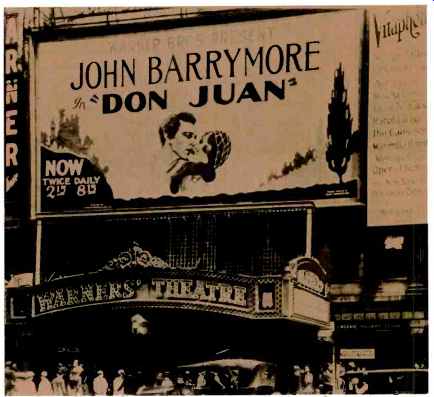
---The first sound movie "Don Juan" starring John Barrymore opened
at the Warner Theater in New York City in August, 1926. (Photo-Courtesy of
Bell Laboratories.)
The Wente Bell Lab multicellular horn had a single configuration of 70° X 70° distribution pattern. We made a survey of the theaters and determined we needed several sizes using an arrangement of single cells each 17° x 17° with a 300 Hz cutoff. These took the form of a 2x4, 2x5, 2x6, 3x3, 3x4, 3x5 cells to cover the various sizes of theaters. We had learned from earlier multiple horn use that it was beneficial to reduce both the number of horns and overlapping patterns to a minimum, and hence our objective was to use one high frequency horn whenever possible. Robert L. Stephens of MGM was given the task of laying out the geometry and construction of the multicell horns and having the prototypes built in our precision machine shop. (MGM had foundry casting facilities, precision machine shops for camera and printer repair and a complete wood working plant.) Harry Kimball was assigned the dividing network problem, and I made preliminary designs of flat baffle and horn-loaded low frequency components. At this point ERPI realized we had a viable program and provided us with one of the Fletcher systems. It was at this time we had the experience of learning that time delay and phasing were important considerations as reported in the Eleanor Powell tap dance tests. After extensive time delay tests, we determined that the physical delay between low and high frequency sources should be less than one millisecond.
When the RCA Photophone Division was informed of our goal, Harry Olson and John Volkman asked to participate by supplying versions of their loudspeaker systems and expertise, which we gratefully accepted.
By 1935, we had selected a re-entrant low frequency horn suggested by Olson, and it used four 15-in. Lansing type cone drivers and Lansing 284 driver units for the multicell horns.
The MGM Shearer-type two-way theater sound system had arrived. Doug Shearer and I supervised the installation of 12 systems in various cities for the opening of "Romeo and Juliet" featuring Norma Shearer, Doug's sister. These systems were built in the MGM studios. After completion of the installation, RCA and ERPI each were given contracts to supply 75 systems for the Loews Theater Circuit.
Other theater chains followed with orders, and the Academy of Motion Picture Arts and Sciences theater standardization research council was formed. I was made chairman. All studios participated, and we specified the minimum power requirements, theater acoustic recommendations, and a standard electrical characteristic since ERPI, RCA, and Lansing were supplying their versions of the two-way system for theater use.
Divide and Merge
In 1938, a consent degree removed Western Electric (ERPI) from manufacturing and selling theater sound equipment and having service contracts for theater equipment. In December, 1938, this part of ERPI was sold to an ERPI employee organization approved by Western Electric.
The new company was organized by M. Conroe and G. Carrington who had managed the ERPI theater division. The name selected was Altec Service Corp. (derived from all technical). They acquired all the equipment, contracts, and personnel who wished to transfer from ERPI to Altec.
By 1941, the Western Electric inventory acquired in the take over was becoming exhausted, and George Carrington asked for a recommendation for equipment sources. I suggested Altec buy Lansing which was done, and Altec Lansing Corp. was formed in May 1941. In the interval between 1938 and 1941, Bob Stephens had resigned from MGM and formed the Stephens Manufacturing Co. where he developed a line of home system loudspeakers in competition with the Lansing Manufacturing Co. Ercell Harrison at Lansing Manufacturing Co. in 1937 developed a line of transformers under contract to MGM to rebuild the entire MGM recording plant. These transformers were soon known as the 20-20 line (20 Hz-20,000 Hz). They had overall characteristics superior to any commercial transformer line available in the U.S. They also became part of the amplifier used in the Lansing Iconic (Greek for likeness), a small two-way monitor system used as the standard loudspeaker in many labs such as CBS, NBC, Dr. Knudsen's lab at UCLA, and as phonograph recording monitors. I left MGM in 1942 to work at the MIT Radiator Laboratory. In 1943, George Carrington arranged with MIT that I work at Altec Lansing on a magnetic airborne submarine detection device for which Altec Lansing had received a contract to develop. In 1945, we had ready the new two-way system called the "Voice of the Theater" which included improved horns and permanent magnet drivers.
Around 1949, Jim Lansing began to have serious differences with Altec Lansing management and finally resigned. He formed a company in Santa Monica and manufactured loudspeakers, but financial troubles overtook him and the Marquardt Co. in Van Nuys supplied funds. However, he had problems there, and Bill Thomas came in and worked with him. Jim Lansing was a despondent person during these difficult times and retired to his avocado ranch in Escondido. Here, he twice attempted suicide, and on the third try, succeeded. His original partner, Jim Decker, was killed in an aircraft accident earlier. After the death of Jim Lansing, Bill Thomas became president of the now J.B. Lansing Sound Inc. Bob Stephens died in 1953, Douglas Shearer died in 1969, and I am left to tell the tale of how this group was instrumental in formulating the early works of quality sound reinforcement, theater systems, and hi-fi home music.
(Source: Audio magazine, March 1977; John K. Hilliard* [*John K. Hilliard & Assoc., Santa Ana, Calif. ])
= = = =