Manufacturer's Specifications:
Number of Channels: Two.
Modulation System: PCM using standard NTSC TV signals.
Sampling Frequency: 44.056 kHz.
Recording Density: 1.726 Mbit/S. Code: 94 bits/horizontal; 16 bits for CRC (Cyclic Redundancy Check) circuit.
Data: 13 bits x 2 channels.
Quantization: 3 polygonal line quantization, 13 bits (equivalent to 14 bits).
Dynamic Range: Record/playback, more than 85 dB.
Harmonic Distortion: Less than 0.03 percent.
Frequency Response: 2 Hz to 20 kHz, ±1 dB. Input Sensitivities: Mike, 0.3 mV minimum; line, 0.095 V minimum; video, 1 V p-p normal.
Output Levels: Line, 0.435 V normal; video, 1 V p-p normal.
Power Requirements: 120 V, 60 Hz, 60 W.
Dimensions: 17 in. (43.18 cm) W x 634 in. (17.15 cm) H x 17 in. (43.18 cm) D. Weight: 41 lbs., 13 oz. (19 kg).
Price: $4,400.00.
-- --
To paraphrase a well-known philosopher, I have seen (heard) the future of audio and it is digital! After a great deal of anticipation, I was finally loaned a sample of the world's first and, as of this writing, only consumer-type digital audio recording adapter; I then spent a couple of weeks putting it through its paces and, at the same time, learning a bit about digital audio tape recording. Calling the PCM-1 an adapter s, perhaps, a bit misleading if not demeaning. One doesn't normally think of adapters as products that sell for more than most high-end audio components, but there is really no other word to properly describe the function of the PCM-1.
As most readers of Audio surely realize by now, the PCM-1 s really an elaborate form of signal processor, one which must be used in conjunction with a suitable video cassette deck. In that connection, a somewhat amusing story must be old. Naturally, Sony advises users to employ the Sony Betamax video tape deck to obtain "best results" with the PCM-1. They were kind enough to supply a portable version of Betamax, the Model SL-3000, to use with the PCM-1. I quickly discovered that this portable model had no separate provisions for connecting the required "video in" and "video out" cables supplied with the PCM-1. Access to these terminals on the SL-3000 was only via an elaborate multiple-pin connector intended for Sony's video cameras, and the appropriate cable was not supplied.
For reasons which will become obvious in a moment, remained undaunted and simply hauled out my JVC video portable which employs the competing VHS video taping format. Of course, it worked perfectly with the PCM-1, as would any video cassette recorder that can handle a standard NTSC video signal, for that is what one is actually dealing with when using this PCM-1 unit.
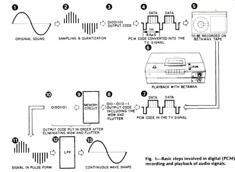
Fig. 1-Basic steps involved in digital (PCM) recording and playback of audio
signals.
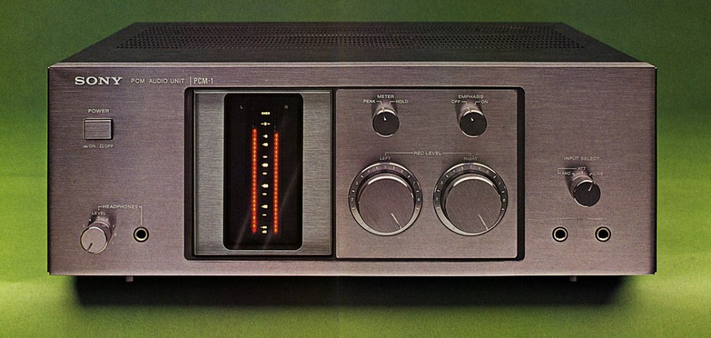
As for the PCM-1 unit itself, externally at least, it is a deceptively simple-looking box. On the 'front panel are a Power On/Off button at the upper left, a headphone jack and associated level control at the lower left, two large record level controls to the right of center, a pair of mike jacks at the lower right, an input selector switch for mike/mike attenuator/line inputs above the mike jacks, and a pair of switches above the level controls. One of these switches selects peak or peak-hold functions for the vertically oriented LED meter displays, while the other introduces or cancels a 50-microsecond pre-emphasis/de-emphasis circuit. The purpose of this pre-emphasis/de-emphasis will be described later, when we discuss the circuit features of the PCM-1.
The LED metering system, consisting of two rows of vertically arranged LEDs, covers a wide range from-60 dB to 0 dB. Unlike conventional analog recorders, the 0-dB mark is the absolute maximum level which can be recorded, and any attempt to record at higher levels results in severe distortion.
For this reason, "clipping" indicator lights are provided at the top of the meter scale. Normally, these LEDs should never be permitted to light. While the 0-dB maximum restriction takes a bit of getting used to for those of us who have traditionally allowed meters on analog recorders to exceed that limit, it in no way restricts the tremendous amount of dynamic range which can be accommodated by this digital recording system.
The rear panel of the PCM-1 is equipped with line-in and line-out terminals in the form of phono tip jacks as well as XLR-3 Cannon-type connectors, so that professional mike mixers and professional line amplifiers can be connected.
Video output and video input jacks enable the user to interface with the required VCR, while a convenience a.c. outlet supplies up to 300 watts of a.c. power for any auxiliary equipment.
The system employed in the PCM-1 is probably familiar to most readers, but a brief review may be helpful to those who are not acquainted with digital recording principles. The diagram of Fig. 1, supplied in Sony's excellent technical information manual, breaks down the process into 13 steps, beginning with the desired audio waveform to be recorded, its sampling and quantization, conversion to binary code data and to a standard video signal format, storage on video tape, playback of the video signal via a memory circuit (to smooth out any and all wow and flutter), reconversion to a signal in pulse-quantified form, and low-pass filtering to recreate the original continuous audio waveshape.
Circuit Description
The block diagram of Fig. 2 illustrates the basic circuit elements employed during audio recording using the PCM-1, while Fig. 3 shows the circuit elements employed during playback. Referring to Fig. 2, line or microphone input audio signals are first amplified either by a differential mike amplifier or by a line input buffer amplifier. After suitable attenuation by means of the record level controls, a line amplifier amplifies the audio signals, applies pre-emphasis if desired, and applies "dither" oscillations or noise. In order to quantize analog signals with the least significant bit in a PCM system, the playback signals will take on a stepped configuration and harmonic distortion would be generated when signal levels are low. However, if a certain kind of noise is superimposed on the signals, the THD is converted into random noise which bears no relationship to harmonics of the audio signal. The noise thus applied is called "dither," and the PCM noise level is almost always determined by it. In the PCM-1's dither generator, zener diode noise is passed through a low-cut filter and amplified, while its level is made uniform by an a.g.c. circuit.
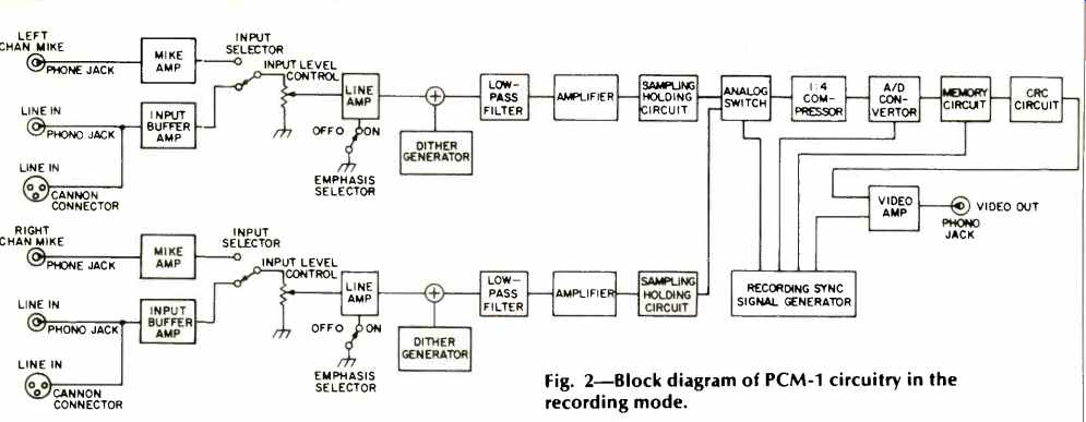
Fig. 2-Block diagram of PCM-1 circuitry in the recording mode.
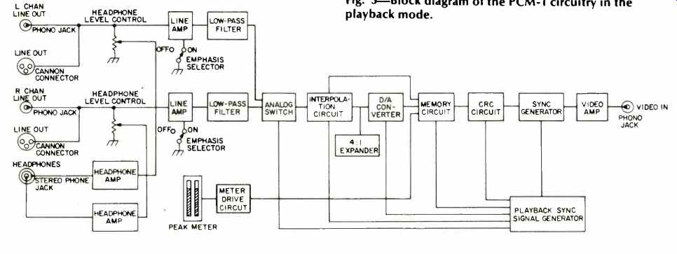
Fig. 3-Block diagram of the PCM-1 circuitry in the playback mode.
The pre-emphasis is designed to reduce the amount of dither noise and enhance S/N ratio still further by boosting high-frequency response during recording and lowering it during playback. Time constants used are 50 uS and 15 uS, and S/N is improved when using the emphasis circuits by about 7 additional dB. Incidentally, while emphasis must be selected (if desired) during recording, the front panel switch can be left in either position during playback, since de-emphasis is applied automatically by sensing circuits within the unit, when required.
Because of the relatively low sampling rate employed in the PCM-1, it is necessary to attenuate any audio signals above 20 kHz and that is the purpose of the low-pass filters shown in both the record block diagram (Fig. 2) and the playback diagram (Fig. 3). In order to sample a continuous stream of analog signals, it is necessary to sample them in an extremely short time. The circuit that performs this function is known as a "sample and hold" circuit. A CMOS analog switch is used to apply the left-channel and right-channel signals alternately to the analog-to-digital (A/D) converter.
By employing a 4:1 compressor in the record chain and a 1:4 expander in the playback signal chain, the PCM-1 provides the equivalent dynamic range of a 14-bit system while in reality employing only a 12-bit code. The task of converting the signals into digital signals is performed by the A/D converter, while the reverse task during playback is performed by the D/A converter shown in Fig. 3. In the PCM-1 left- and right-channel signals are combined (in the analog switch) into a series of pulses on a time-sharing basis. A single complex IC is used for the A/D and D/A conversion.
The PCM-1 is designed so that dropout errors in the data recorded on the tape can be corrected and will not become part of the reproduced sound signal. An interpolation circuit substitutes the average value of samples before and after the code error when incorrect codes occur. Digital signals derived from the A/D converter are fed to the memory circuit.
In this circuit the continuous stream of PCM signals are compressed since it is not possible to record data during the horizontal and vertical sync and blanking periods of the standard TV signal.
The CRC circuit stands for Cyclic Redundancy Check and is used in connection with error detection and correction codes. The circuit applies a 16-bit redundancy code to a single horizontal sync period in order to detect data errors when they are produced during playback by dropouts in the tape.
Next, the video amplifier mixes the digital signals with standard TV sync signals (vertical and horizontal) which are produced by the recording sync signal generator. Video output is approximately 0.7 volts p-p, at 75 ohms impedance. The recording sync signal generator divides down a quartz-controlled oscillation at 14.068 MHz to provide the precise frequencies required in the A/D converter, memory circuits, etc. and also generates the aforementioned TV sync signals.
In playback, the sync separator circuit shown in Fig. 3 separates the PCM data from the video sync pulses. The CRC circuit detects data errors caused by dropouts, as previously mentioned. The memory circuit absorbs any jitter in the playback signals that might be caused by tape transport wow and flutter. D/A conversion follows, and the recovered pulses are then expanded by 1:4, following which the interpolation circuit compensates for any dropout code errors. The analog switch function has already been described, and once the correct pulses have been routed to left- and right-channel signal paths, low-pass filters smooth out the pulses, recreating the continuous waveforms which constituted the original audio signals.
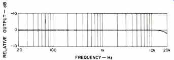
Fig. 4-Record/playback response at "0 dB" record level, using
the PCM-1 with VCR recorder.
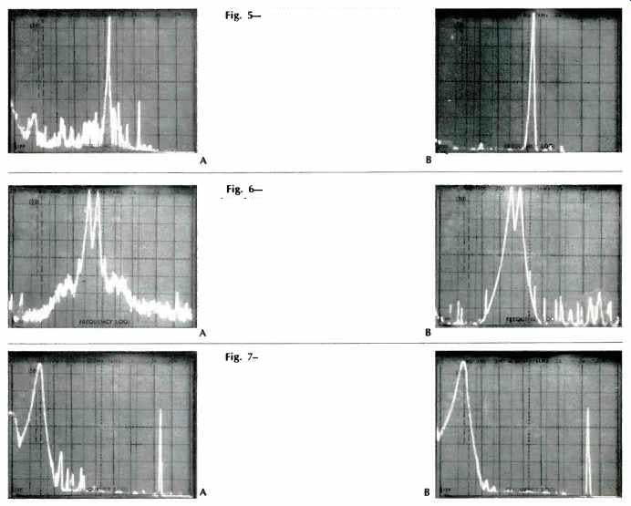
Fig. 5-Oscilloscope photo A shows noise and THD components associated with
a 1-kHz signal (spike at center) recorded at 0 dB. Compare this with results
obtained using the PCM-1 in photo B.
Fig. 6-Oscilloscope photo A shows two-tone (9 and 10 kHz) IM test results
using high-quality analog deck. Photo B shows results obtained with PCM-1.
Fig. 7-Spectrum analyzer display of playback of recorded SMPTE IM test signal for open-reel analog deck at 15 ips in photo A and for PCM-1 system in photo B.
Laboratory Measurements
We treated the PCM-1/VCR recorder combination on the lab bench in much the same way as we would any audio tape recorder, making the same sorts of measurements which we would make for a fine audio cassette or open-reel tape deck.
Of course, the nature of the combination is such that it is not possible to monitor resulting recordings as they are being made. So, to plot frequency response, we recorded spot frequencies in the range from 20 Hz to 20 kHz. Unlike the situation with conventional analog tape decks (especially cassette decks), we were no longer restricted by high-frequency tape saturation and were therefore able to plot record/play response at 0-dB record level (as indicated on the PCM-1's LED meters). Results are shown in Fig. 4, and you will simply have to take our word for it that they are in no way exaggerated.
Response was down 2.0 dB at 20 kHz, as the action of the low-pass filter began to be felt.
We decided pretty early on in our bench tests that the only way to really show how magnificent thus digital recording system is would be to compare results, graphically, with results obtained from our own half-track reel-to-reel tape deck operating at its top speed of 15 ips. The two 'scope photos of Fig. 5 tell the story most graphically. Fig. 5A shows noise and distortion associated with a 1-kHz signal recorded on the analog deck at 0-dB record level, while in Fig. 56 we see the results obtained using the PCM-1 (also at 0-dB record level). Actual THD at 1 kHz measured an incredibly low 0.03 percent using the PCM-1, exactly as claimed. Signal-to-noise ratio, referred to the same 0-dB record level, measured 82 dB. Next we measured CCIR IM distortion, using a two-tone test signal of 9 kHz and 10 kHz. For the PCM-1, the CCIR IM measured a low residual 0.0017 percent (the limits of our test signal source), while in the case of the analog recorder used for comparison, we read 0.05 percent. Spectrum analysis of the results are shown in the two 'scope photos of Fig. 6. Note the modulation noise surrounding the two tone spikes in Fig. 6A and the complete absence of such noise in Fig. 6B. The sharp spikes that are present in Fig. 6B should not be confused with distortion components. They were, rather, small dropout spikes from the tape which look a good deal worse on the analyzer than they actually sounded. The tallest of these random "ticks" is a good 65 dB below reference signal level in any case and, audibly (while listening to a steady-state tone), they sound like very subdued little pops that my technician and I both describe as "pop corn" noise for want of a better term. Under actual music listening conditions, however, they were completely masked and totally inaudible.
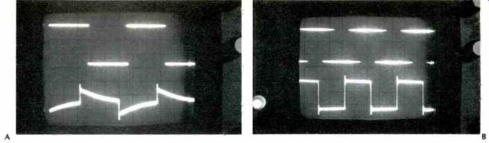
Fig. 8-Reproduction of 100-Hz recorded square wave signal on the analog
O-R tape deck in photo A and on PCM-1 in photo B. Upper display is input
in both cases.
Fig. 9-Stored spectrum analysis of dynamic range and frequency distribution
of wide dynamic range music from a decoded dbx disc recorded using PCM-1
and VCR.
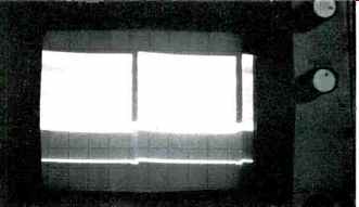
Fig. 10-Recovered signal from VCR, before connection to the PCM-1, is the
familiar video signal that one would expect. Spaces are vertical sync pulses
and blanking between frames.
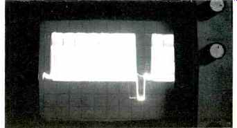
Fig. 11-One "horizontal line" of video signal at output of VCR
contains several "words" of digitized audio information.
Anyone who has ever taken the trouble to measure SMPTE IM distortion in a tape deck knows that the numbers are pretty horrendous. In the case of our open-reel deck we measured an IM of 2.8 percent at 0-dB record level. For the PCM1 we measured a mere 0.07 percent, most of which appeared to be in our signal source and not a product of the taping and playback process! Analysis of the played-back 60 Hz and 7 kHz SMPTE IM signal was made using the spectrum analyzer, and results are displayed for the open-reel deck and for the PCM-1 in Figs. 7A and 7B. Trying to record a square wave on any analog tape deck almost always results in a disappointment, as is clearly illustrated in Fig. 8A. Note, however, how close we were able to come to reproducing such a square wave from a tape recording in the case of the PCM-1, as shown in Fig. 8B. Having convinced ourselves that the PCM-1 used with a VCR can do an incredible audio recording job using test signals in a laboratory environment, we were now faced with the problem of attempting to verify its recording and playback capabilities using musical program material. What in the world were we to use as a program source? Clearly, any transcription of existing tapes (even master tapes) or the very quietest records we own would prove nothing. Their dynamic range and signal-to-noise qualities would fall far short of indicating just how much dynamic range the PCM-1 could handle. Nor did we have access to any live symphony orchestra concerts during the weeks that we had the PCM-1 in our possession. What to do? We finally came up with our own scheme which, while admittedly a bit unusual, served the purpose. Having recently acquired some of the new dbx-encoded "noiseless" discs and the necessary decoder with which to play them, we decided to record the decoded signals from such discs directly through the PCM-1 and the associated VCR recorder. Dbx discs offer the possibility of at least 80 dB of dynamic range and an almost complete absence of audible surface noise.
Sure enough, the scheme worked at least well enough to prove the point. During playback of the VCR tape we let our spectrum analyzer sweep continuously for about 20 minutes, storing the varying amplitudes on the storage 'scope facilities associated with the analyzer, and this "collection" is shown in Fig. 9. The total amplitude range on the 'scope face from bottom to top is 80 dB (10 dB per division), while frequencies extend from 20 Hz to 20 kHz from left to right. Note that in the vicinity from 100 Hz to 250 Hz amplitudes actually went "off-scale," indicating a dynamic range in excess of 80 c113 (since "silence" was represented by the baseline at the bottom of the display). While reproducing this music, we continuously monitored a regular oscilloscope visually, to which the output of the recovered signals from the PCM-1 were applied, and at no time did we see any evidence of clipping or overload. While access to live music might have beer more exciting, we feel that this roundabout method did confirm the PCM-1's dynamic range capability of 80 dB plus.
While an investigation of the nature of the "video" signal recorded on the tape will not serve to characterize the quality of sound reproduced from the PCM-1/VCR combination we were nevertheless curious to see what this recorded signal (as "read" from the VCR tape itself) looks like. Figure 10 shows the actual video signal recorded on the tape for about two vertical frames, while in Fig. 11 we have expanded the display (increased sweep speed) to capture z bit more than one horizontal line of the standard video signal observed at the output of the VCR. If you look carefully at this "line" of video information, you can see the spaces separating individual 13-bit words. The downward-going pulse at the right of the display is, of course, the horizontal sync pulse that should be familiar to anyone who has done any TV servicing.
We couldn't resist the temptation to see what the digitally recorded signal might look like if displayed as a video picture on a TV screen. So, just for fun, we hooked up the VCR to our TV set and played the digitally recorded tape. Interpreting the published specifications, we believe that what you see in Fig. 12 are approximately 49,350 "bits" of digital information, arranged in discrete 13-bit "words" to describe the samples of the original audio signals which we recorded onto this tape. Again, the spaces between "words" are clearly discernible. To get this photo required a time exposure and, as you might guess, the pattern is constantly changing at an incredible rate. Fortunately, our VCR is equipped with stop-frame action, so by "locking onto" a single video "frame" we were able to photograph this striking display. When you think about it, the density of information in just this single frame is enormous! It goes without saying that in terms of sound quality, absence of distortion, total lack of wow and flutter, signal-to-noise ratio and dynamic range, the PCM-1 unit used in combination with a VCR tape deck runs rings around any analog tape recorder I have ever had an opportunity to use or test.
That's not to say that there are no disadvantages for the serious home recordist in using a system such as this. The most obvious of these, of course, is price. I do not know whether Sony intends to seriously promote this product to retail customers at its present $4,400.00 price level, but if they should do so, there are still the problems of lack of editing capability. You can't just rip into a video cassette package, and even if you could, you'd have a hard time editing this kind of recorded information in the usual "razor blade and splicer" manner.
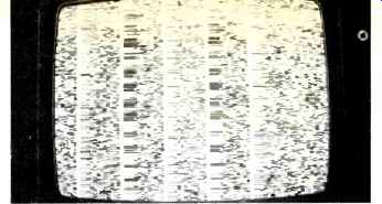
Fig. 12-This is what one frame of digitally recorded audio signal looks
like when played back on a TV monitor screen.
Then, too, the PCM-1 circuitry is arranged in such a manner that no LED meter indications are perceived until you activate the associated VCR to which it is connected. That means that to "cue up" record levels, you have to place the VCR in the pause mode-a mode that is not recommended for more than a few minutes if you don't want to damage the tape or the tape head.
For all of these minor disadvantages, it is very clear to me that someday all of us will be recording audio signals in this completely digitalized form. I am grateful to the people at Sony for providing their PCM-1, whose development must have represented an enormous investment with little possibility of immediate return. I am particularly grateful to them too for providing my first practical lesson and experience in digital audio recording. Now that this ground has been broken, it won't be too long before we can purchase digital recording equipment at more down-to-earth prices.
-Leonard Feldman
(Source: Audio magazine, Mar. 1980, Leonard Feldman)
Also see: Sony PCM-F1 Digital Audio Processor (Mar. 1982)
SONY PCM-501 ES Digital Audio Processor (Sept. 1985)
= = = =