by Herman Burstein
THE CURRENT National Association of Broadcasters (NAB) Standard for Magnetic Tape Recording and Reproducing (Reel-to-Reel) appeared in April 1965.
Although more than 10 years have passed, the nature of standard tape equalization tends to remain obscure and imperfectly understood. I gather this both from audiophiles' questions and statements that are made in some of the popular periodicals devoted to audio.
Such misunderstanding is partly due to the complexity of the subject, which entails the velocity characteristic of the playback head; gap loss, electrical losses, resonance effect, and contour effect of the playback head; electrical losses of the record head; magnetic losses of the tape; surface induction of the tape; magnetic flux entering the core of the playback head; maximization of signal-to-noise ratio; minimization of distortion, and achievement of flat record-playback response.
Misunderstanding is also due to the indirect and piecemeal manner in which the equalization standards are presented. The playback curve in the 1965 Standard is visually much different than the playback curve ordinarily shown in the popular audio periodicals, although one is translatable into the other. The 1965 Standard shows a playback curve with apparent treble boost and bass cut, whereas the curve popularly shown has treble cut and bass boost. To put the entire NAB equalization standard together, one has to hunt through various sections of the 1965 Standard, including footnotes. One finds only hints, rather than a straightforward statement, that record-playback response should be flat (within certain tolerances). Presumably an understanding of standard tape equalization is desirable to the audiophile, perhaps as knowledge in itself and perhaps to assist him in the use, modification, and even construction of tape equipment. To provide this understanding, we shall assume operation at a standard speed of 7 1/2 ips. In principle, what is said about 7 1/2 ips applies to other speeds, except for differences in amount of frequency losses and therefore in equalization required. We shall also assume operation at "normal bias" for a given recording tape-the tape recommended by the tape deck manufacturer and/or chosen by the user. Normal bias is approximately that which minimizes distortion in recording.
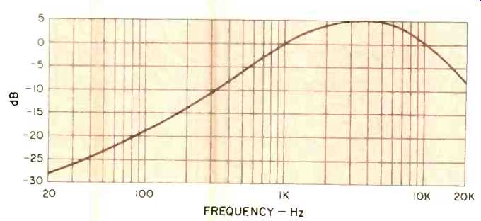
Fig. 1-Typical unequalized record-playback response of a tape deck at 7 1/2 ips.
Unequalized Record-Playback Response
First we require a clear understanding why equalization is needed. Therefore, Fig. 1 shows the typical unequalized record-playback response of a high-quality tape deck at 71 ips, using good tape, with normal bias for this tape. Although input to the deck is flat-constant amplitude for all frequencies in the audio range-output is anything but flat.
Output rises steadily until about 4,000 Hz and soon after drops quite abruptly.
Ideally, record-playback response should be flat (or nearly so), represented by a horizontal line throughout the audio range. Clearly, bass boost and treble boost are needed to restore flat response.
Departure of an unequalized tape system from flat response is largely explained by two factors: (1) rise in output of the playback head as frequency increases; (2) serious treble losses on the tape owing to magnetic phenomena.
These and other factors are examined in the next two sections, which respectively deal with playback "losses" and record "losses." We put the term losses in quotes to draw attention to the fact that, like the NAB Standard, we will use it in both a positive and negative sense: Losses include gains as well as declines in frequency response. In other words, losses designate both upward and downward deviations in response.
Playback Losses
In playback, the chief deviation from flat response is due to the playback head being a velocity device. As such, it produces steadily rising output voltage in response to a flat input signal (constant magnetic flux in the core of the head). This rise, illustrated by the solid line in Fig. 2, amounts to 60 dB over the audio range of 20 to 20,000 Hz.
A velocity device is one whose output voltage is proportional to the number of changes per second in a magnetic field. For a playback head, the changing magnetic field is due to the signal recorded on the tape. In short, head output is proportional to signal frequency (assuming all frequencies are recorded so as to produce equal flux in the core of the head). Thus, if frequency doubles, voltage output of the head doubles. One octave represents a doubling of frequency, while 6 dB represents a doubling of voltage.
Therefore, as in Fig. 2, playback head output tends to steadily rise 6 dB per octave. (More accurately, output rises 6.0206 dB per octave, or exactly 20 dB per decade, on 10-fold rise in frequency such as from 100 to 1,000 Hz.) A steady 6-dB-per-octave rise characterizes an ideal playback head-one with no deviations from Fig. 2. However, a practical head displays some irregularities. For a high-quality head operating at 7 1/2 ips, the irregularities are quite minor and are as follows.
1. Treble Loss Due To Gap Width. Modern playback heads have gaps as narrow as 4 microns (.000160 in.) or less, sometimes approaching 1 micron (.000040 in.). A useful formula for approximating playback head response before gap loss becomes appreciable is f = 0.85S _ 2G, where f is frequency in Hz, S is tape speed in ips, and G is gap width in inches. Substituting 7.5 for S and 0.000160 (4 microns) for G, we find that f is about 20,000 Hz. If the gap is appreciably narrower than .000160 in., significant treble loss owing to the gap does not occur until well above 20,000 Hz. Therefore, in the case of a high-quality playback head operating at 7 ½ ips, gap width accounts for negligible deviation from Fig. 2. (The horizontal dimension of the gap is usually called gap width in the popular literature and gap length in the technical literature, such as the NAB Standard.)
2. Electrical Treble Losses. These are largely due to hysteresis and eddy currents in the core of the playback head, and to winding capacitance of the head. Partially offsetting these is a resonance effect due to the head capacitance in series with load capacitance. For a well-made playback head in a well-designed circuit, the net electrical loss tends to be very little within the audio range, perhaps in the vicinity of 1 to 3 dB at 20,000 Hz.
3. Bass Rise Due To Contour Effect. As frequency declines, wavelength of the signal recorded on the tape grows longer. (Wave length is tape speed divided by signal frequency, or inches of tape per audio cycle.) As recorded wavelength increases, the entire playback head (not only the gap) reacts to the tape's magnetic field, augmenting response. Thus, the output of the playback head tends to rise in the bass region relative to the theoretical, or ideal, response slope of 6 dB per octave. The nature and extent of this relative rise in bass depends in part upon the angle at which the tape approaches and leaves the head. Sometimes the effect of this angle is separately identified as the "wrap effect." However, we can conveniently combine all these phenomena under the single term "contour effect." For a well-designed playback head in a well-designed transport, the contour effect tends to be moderate-resulting in something like 3 dB relative bass boost at 50 Hz.
Altogether, for a flat signal input, the irregularities in output of a high-quality playback head cause it to deviate very little from the ideal response of Fig. 2. In other words, for constant magnetic flux in the core of the head, output would typically be about that of Fig. 3. Here the response rises 6 dB per octave through most of the audio range, but at a slightly slower rate in the low bass and in the high treble owing to the contour effect, gap loss, and electrical losses.
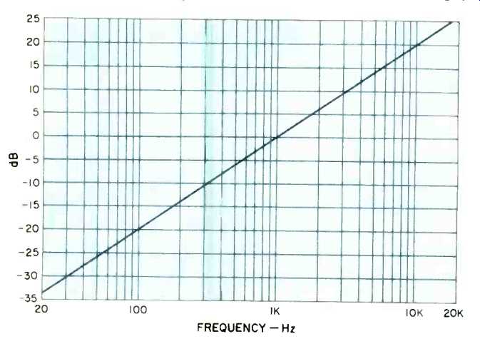
Fig. 2-Response of an ideal magnetic flux in its core.
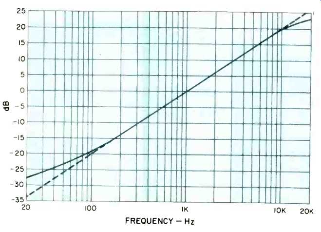
Fig. 3-Typical response of a practical playback constant magnetic flux in its core.
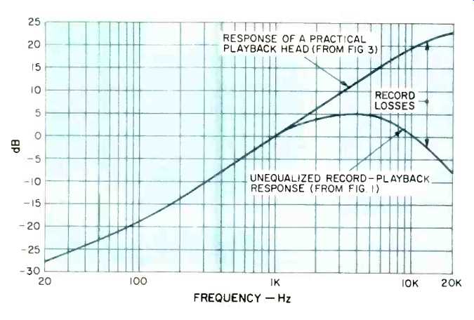
Fig. 4-Typical record losses at 7 1/2 ips.
Record Losses
Figure 4 compares the response of a practical playback head with unequalized record-playback response. The difference between the two curves is due to losses in recording. Playback head response assumes constant magnetic flux in the core of the head owing to a flat signal on the tape.
Unequalized record-playback response reflects the actual signal on the tape-one that embodies vast treble losses.
Depending upon the kind of tape employed and the amount of bias, the treble losses in recording may vary somewhat from those shown in Fig. 4. Typically, however, they total around 30 dB at 20,000 Hz at 7 1/2 ips. (They are appreciably smaller at 15 ips and appreciably larger at speeds below 7 1/2 ips.) In order of importance, following are the factors that cause record losses.
1. Self-Demagnetization. Frequencies recorded on tape are in effect a series of bar magnets oriented lengthwise on the tape; each bar magnet corresponds to a half-cycle. The opposing north and south poles of a bar magnet tend to cancel as the bar becomes shorter. With increasing frequency, the recorded wavelength (tape speed divided by frequency) becomes shorter, thus the bar magnets become [...]
(Audio magazine, Herman Burstein)
Also see:
= = = =