Author: Herman Lia [Senior Engineer, Tandberg Radiofabrikk A/S, Oslo, Norway ]
The enormous sale of cassette tape recorders in the last few years is proof enough that this product meets a demand.

At the same time there is a danger that people will forget the open -reel tape recorder, which in many important respects is a much better basic concept. A cassette machine's advantages are that it is easy to operate, weighs very little, and that a broad range of prerecorded tapes are widely available. On the other hand, as this article will show, cassette machines will always be inferior to open -reel machines when the major performance characteristics, such as signal-to-noise ratio, are compared. At the same time, it must be admitted that for a large number of consumers, cassette machines are usually quite good enough. However, when the very best quality recording is required, an open -reel machine must be used. To be fair and realistic, we must also say that cassette machines have expanded the total market for tape recorders, as well as capturing a portion of the open reel market. However, they will never take over all of the open-reel market because there are fundamental differences in the quality level obtainable with the two systems, differences which result from the internationally recognized standards governing each system.
General Considerations
The two most important characteristics that determine the performance of a tape recorder are signal-to-noise ratio and frequency response. In this context, frequency response means a response relative to a signal level that lies substantially below the saturation curve of the tape and substantially above the level of residual tape noise.
Let us consider a tape recorder as a black box where we connect a signal to the input and take out another signal from the output, as shown in Fig. 1.
Ideally, the only differences between the input and the output signal are time delay and possibly some scale or amplification factor, A. The lowest possible time delay is determined by the distance between the record and playback heads, together with tape speed. Unfortunately, real world tape recorders are not ideal, and we need to make some measurements to discover their characteristics. We can begin by measuring signal capacity. We do this by applying a single tone at a particular frequency to the input and then raising the input level voltage ei(t) until the signal at the output has a particular amount of distortion, e.g. 5 percent harmonic distortion. This can be done for a number of frequencies, and the typical results are shown in Fig. 2 for one particular tape speed. Next we remove the input signal ei(t) and short circuit the input. There should, of course, be no signal at the output, but in practice there is a noise spectrum which is the sum of the residual tape noise and the noise from the record and playback electronics.
In a well-designed tape recorder, the noise from the electronics is so low that the dominant noise component is the tape noise. The noise spectrum can be analyzed by mean of one-third octave filters, and this is shown in Fig. 2 along with a saturation curve.
These measurements tell us quite a lot. They tell us that there are upper and lower limits of the signal a tape can accommodate with acceptable quality. If the input signal is too high, the distortion will be above the acceptable maximum, and if the input signal is too low it will get lost in the noise.
The distance between the two curves in Fig. 2 at an individual frequency is therefore a measure of the signal capacity of the tape recorder at individual frequencies, while the total area between the two curves is a measure of the signal capacity over a chosen frequency range.
Using information theory, the signal capacity can be defined for a general transmission channel by the following integral:
SB = ∫ B (S+N/N) df (1)
where SB is the signal /bandwidth product, S is the signal, N is the noise, and B is the bandwidth. This is Shannon's definition of signal capacity, given in 1948.
Now, since log S+N/N = log (S+N) - log N, equation (1) can therefore be rewritten as:
SB = ∫ B {log (S+N) log N } df (2)
This precisely defines the area between the signal and noise curves in Fig. 2, and therefore equation (2) gives us an opportunity to put forward a quantitative measure of a tape recorder's ability to accommodate signals. More exact theoretical considerations we have developed show that the SB product for a tape recorder is given by:

Bs = Induction in the tape caused by the signal (Gauss)
Br = Maximum remanent induction (Gauss)
He = Coercivity (Orsteds)
v = Tape speed
b = Track width
d = Thickness of oxide coating
fo = Highest frequency considered
N(f) = A characteristic function of tape noise.
The most important conclusion to be drawn from equation (3) is that the SB product is dependent on the physical properties of the system, such the tape speed, track width, tape parameters, and so on, rather than the electronics, as long as we maintain the true dynamic range in the program which is to be recorded with no signal processing.
We will see later that it is possible to process the signal so that the tape hiss becomes less audible to the listener.
Despite this conclusion, we find the frequency -dependent equalization in a tape recorder greatly affects the audible results. We should, therefore, take a closer look at the main requirements influencing the choice of these equalizations. These turn out to be maximum subjective signal-to-noise ratio and flat frequency response at low signal levels.
The measurements for Fig. 2 were made with one particular playback equalization (120 RS). If we choose another equalization, say 50µS, and make additional measurements, we obtain the curves shown in Fig. 3. Note that the distance between the two curves is the same, but the shapes of the curves have changed. When we record a program, we are dealing with a complex signal with a particular power distribution over the frequency spectrum, and it should be obvious that we will obtain the best subjective signal-to-noise ratio if we can "pack the sound" as far as possible up under the tape's saturation curve.
Let us assume that we have a program with relatively little power in the high frequencies. We then set the input sensitivity of the system to fully load the tape at the middle and low frequencies. If we use the 120µS playback equalization, the high frequencies will lie far under the tape's saturation curve and therefore near to the noise level. In this case, we could advantageously alter the equalization to 50 µS, say, and thereby drop the noise level away from the signal. If we change the equalization or time constant in this manner, to improve the signal-to-noise ratio, we must be consistent and change the input level to produce the flat test frequency response at low levels. On the other hand, if we now have a program with a lot of power in the high frequencies, a time constant that is too short will cause the high frequencies to overload the tape before the tape is saturated at the low frequencies, and low frequency noise can then become a problem. From this discussion, we can see that the SB product defined in equation (3) is an objective measure of the best signal-to-noise ratio that can be obtained.
Frequency -dependent equalizations are thus used to match the characteristics of the tape to practical conditions and produce the best signal-to-noise ratio, which means that the SB product is exploited to its maximum. At the same time, we have seen that the optimum playback equalization depends on the type of program the tape recorder must handle. We are therefore led to seek a dynamic equalization that automatically adjusts itself to the power -frequency curve of the program being recorded. This is exactly the concept behind complementary noise -reduction systems, such as Dolby, dbx, Burwen, etc. If we make the same measurements used in Fig. 2 with a Dolby circuit added, we obtain the curves shown in Fig. 4.
At the higher input levels, the signal is not processed and the tape recorder performs as if the Dolby circuit had not been included. When the signal falls, the higher frequencies receive extra amplification and are, therefore, recorded with a larger margin above the tape noise than normal. During playback the opposite process occurs, and the overall frequency response is therefore correct.
Increased amplification of the higher frequencies during recording requires reduced amplification of the same frequencies during playback (complementary system). Therefore, noise and other unwanted signals introduced in the process after encoding and before decoding are reduced.
Tape noise is reduced by the same degree as the processing of the signal. Figure 4 shows typical output of a cassette machine with a time constant of 120 µS. At the higher levels, the signal swamps the noise, and the performance is acceptable. The corresponding noise level is given by curve B. At the lower levels, curve A is of no interest, but the signal processing in the Dolby circuits yields noise curve C which is equivalent to a time constant of 40µS because it has the effect of reducing the noise at higher frequencies by about 10 dB. Accordingly, there is a dynamic change in the time constant from 120 to about 40µS, depending on the amount of high frequency energy in the program.
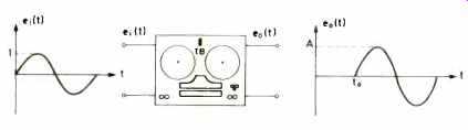
Fig. 1--Ideally the only differences between input and output of a tape
recorder are time delay and possibly amplification of signal.

Fig. 2--Recording system performance, showing maximum output level versus
frequency at a constant 5 percent THD and residual noise level of the system.

Fig. 3--System performance, as in Fig. 2, with two different equalization
time constants, showing how the shapes of the curves change. Note that the
area between the pairs of curves produced by each constant remains the same.
Fig. 4--System performance, as in Fig. 2, but with a Dolby NR circuit added
to reduce system noise.

Fig. 5--Comparison of two systems with the same noise floor, but different
maximum high frequency output curves. While both will have the same signal-to-noise
ratio, when measured via conventional standards, system A will sound better
because of its extended high frequency response.

Fig. 6-Comparison of a Tandberg TB-10X8 open reel recorder with a TCD-330 cassette machine, as in Fig. 2.
Measuring the Signal-to-Noise Ratio
The signal-to-noise ratio is often measured according to the German DIN and IEC standards which defines it as the ratio between the signal at 333 Hz with 3 percent distortion and the tape noise weighted and measured according to the ANSI A weighting curve. One important weakness in these measurement methods is that they only take account of the low frequency signal capacity, and large differences in the high frequency signal capacity can be missed by the measurements.
This point is brought out in Fig. 5; the two curves A and B will show the same signal-to-noise ratio, but without a doubt you will hear the difference on a recording. From the foregoing argument, we can see that the signal bandwidth product is a better measure of the dynamic range.
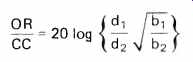
Let us now make a comparison between cassette machines and open-reel machines in the light of equation (3). Experience shows that maximum remanent induction and tape noise characteristics are exactly the same for cassette and open-reel tapes because the magnetic particles, size, and density of the particles are the same for the two types of tape. (While there are differences in tape formulations actually available to the consumer, any formulation can be applied to either system.) Assuming the same bandwidth for open-reel and cassette machines, we can use equation (3) to find an expression that shows the difference in the signal-to-noise ratio for the two systems:

Where, for OR (open reel), d, = 13µm, b, = 1.0 mm, v, = 178, 3 3/4, 7 1, 15 ips, and for CC (compact cassette), d2 = 5µm, b2 = 0.6 mm, v2 = 17.8 ips. The numeric results of (4) for the four speeds are given in the accompanying table where Wo = 23r20 kHz. The results show that tape speed is the dominating factor in the SB product. For cassette machines, tape speed has been prescribed at 1;e ips in the standard, but for open reel the tape speed can go up to 15 ips. In addition, there is an opportunity to choose the most suitable track width with open reel. The table shows that there is 8 dB difference between cassette and open reel at 3 3/4 ips, or that an open reel machines at 3 3/4 ips without Dolby is about as good as a cassette machine with Dolby. It can be argued that it is an advantage not to use any complementary noise reduction system since all forms bring with them undesirable turn-on transients caused by the positive time constants in the control circuits. Furthermore, the Dolby system does not provide any noise reduction at frequencies below 500 Hz, and this is frequently a region where we require an improvement. A poor signal-to-noise ratio at low frequencies causes reproduction to sound impure and damages the quality substantially.

Table I
Let us examine equation (4) for frequencies lower than 500 Hz. This is the case where d <1 and equation (4) becomes:
A new comparison of cassette with open reel at 33/4 ips gives a difference of 10.5 dB, below 500 Hz.
Practical User Qualities
In addition to the considerations concerning recording qualities, it is important to note the differences in user qualities between the two tape recorder systems. Here is a list of points where we feel the open reel machine is superior to the cassette machine:
1) Better signal-to-noise ratio.
2) Acceptable signal-to-noise ratio without noise reduction system.
3) Longer playing time.
4) Greater tape reliability.
5) Better editing facilities.
6) Sound-on-sound recording facility.
7) Better copying facilities.
8) A-B test without adjusting the azimuth when the tape is changed.
9) Less wow and flutter.
10) Better channel separation (track-to-track). The most important advantages of the cassette system are:
1) Easy to operate.
2) Large choice of pre-recorded tapes.
3) Also found in the low price category.
We conclude by presenting measurements made on our TCD 330 cassette machine and the TB 10XD open-reel machine (Fig. 6). The curves tell their own story and are a fitting conclusion to this article.
(Audio magazine, Apr. 1977)
Link | Also see:
Cassette Decks: How Do they Stack Up (Sept. 1975)
Fighting Distortion in Tape Recording (April 1977)
= = = =