Manufacturer's Specifications
Preamplifier:
Gain: Phono stage, 61 dB; line stage, 19 dB.
Frequency Response: Phono, RIAA ±0.15 dB from 20 Hz to 20 kHz, 3 dB down at 220 kHz; line, 0.06 Hz to 650 kHz, +0,-3 dB.
THD + N: Phono, less than 0.025% at 1 kHz, for 2.5 V rms output; line, less than 0.010% at 1 kHz for 2.5 V rms output.
Input Impedance: Phono, user-selectable (see text); line, 10 kilohms.
Output Impedance: Unbalanced, 300 ohms; balanced, 600 ohms.
Maximum Output Level: Phono, 10 V rms; line, 9 V rms.
Power Requirements: 100 to 240 V a.c., user-selectable; 50 watts at idle.
Dimensions: Preamplifier and power supply, each 19 in. W x 1 3/4 in. H x 13 in. D (48.3 cm x 4.5 cm x 33 cm).
Weight: 29 lbs. (13 kg). Price: $4,600.
Amplifier
Power Output: 350 watts into 8 ohms, 700 watts into 4 ohms, 1,100 watts into 2 ohms
Power Bandwidth: 1 Hz to 50 kHz, 3 dB down at 0.15 Hz and 160 kHz.
Slew Rate: 50 V/µS into 8 ohms at 100 V peak to peak.
THD + N (at 1 kHz into 8 Ohms): Less than 0.015% at 20 watts, less than 0.045% at 100 watts, less than 0.06% at 200 watts.
Damping Factor (8 Ohms): Greater than 300 from 20 Hz to 20 kHz, greater than 90 at 100 kHz.
Output Current: 50 amps peak, continuous; 150 amps peak at 1 kHz for 20 mS into 0.1 ohm.
Overall Gain: 26.4 dB. Sensitivity: 136 mV for 1 watt out into 8 ohms.
Input Impedance: Selectable, 100 or 20 kilohms or 300 ohms.
Common-Mode Rejection Ratio: Greater than 90 dB, 20 Hz to 20 kHz.
Power Requirements: 100 to 240 V a.c., user-selectable; 300 watts at idle.
Dimensions: 19 in. W x 8 3/4 in. H x 24 in. D (48.3 cm x 22.2 cm x 61 cm).
Weight: 141 lbs. (64 kg).
Price: $9,800 per pair.
Company Address: P.O. Box 7231, Colorado Springs, Colo. 80933. USA
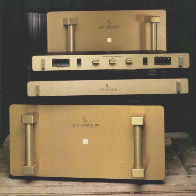
The Model 7 mono power amplifiers are the largest and oldest of the current Jeff Rowland Design Group power amplifier product line. A smaller mono unit, the Model 3, and Model 5 and Model 1 stereo units complete the lineup. The Coherence One Series II is the updated version of the company's only preamp, but a less expensive unit is underway and may be out by the time this review is published. A number of other components are on the drawing board, and no doubt we will be seeing some of these soon.
The Jeff Rowland Design Group believes that electronic design of audio components, when applied with appropriate sensitivity and creativity, can channel life rather than merely reproduce sound. Right on! I believe that, too! Their designs are based on five fundamental principles: Musicality, quality, simplicity, reliability, compatibility with a diversity of equipment and cables, and beauty.
The pieces reviewed here, the Model 7 power amplifiers and the Coherence One Series II preamplifier, are certainly impressive. They are even packed impressively in wooden crates that really protect the equipment during transit. The power amplifiers are heavy, at 141 pounds each. I had to get a friend to help me lift and move these babies around.
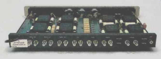
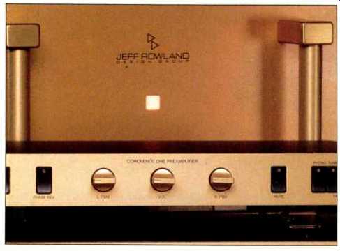
The Coherence One has a separate power supply the same size as the preamp itself; in fact, the power supply is designed to be placed right under the preamp. The power supply is so well shielded that stacking the units does not cause hum pickup. The control layout is symmetrical. The central volume control is flanked by identical knobs for left and right-channel gain trim. At the far left are a group of four _ touch switches for input selection ("Phono," "Tuner," "Tape," and "CD") and a similar switch that inverts the polarity of all main outputs. The controls on the far right are a mirror image of these switches, with a single muting switch and a group of four selecting the signal to be fed to the tape deck ("Phono," "Tuner," "CD," or "Off"). Each touch switch has a built-in LED indicator, and they all control relays that perform the actual switching of the various signals. Found on the rear panel are pairs of gold-plated Tiffany female phono jacks for the inputs, a pair for tape out, and a pair for the positive and negative (inverted and non-inverted) sides of each main output The Model 7 is large, heavy, beefy, and gorgeous! Centered in its massive (1/4-inch-thick), gold-anodized front panel is an alternate-action pushbutton with two levels of illumination to indicate the two states it controls, standby and active. In standby, the switch is softly illuminated and appeared as a light pink. When active, it was a bright amber.
Two large handles grace the front panel and are kind on the hands when horsing the amp around.
On the rear panel are a number of things not found on the usual power amplifier. The output connectors are two 50 ampere barrier strips with #10 screws. The strips are connected in parallel by copper buses to permit both single and bi-wire cable configurations. This connection scheme is said to be sonically superior to five-way binding posts and is compatible with a wide variety of speaker cable terminations. On either side of the output barrier strips are the main power-supply fuses for the output stage. Just below the panel's center are the input connectors, two female Tiffany phono connectors ("Inverting-" and "Non Inverting +") with an XLR differential-input connector between them.
Nearby is a four-pole, single-throw DIP switch that selects input impedance (low, medium, or high). A few inches to the right of the input connectors and impedance switch is a multi-pin DIN connector for remote control of the standby/ operate switch. (This remote switch is available on special order.) At the bottom of the rear panel are the a.c. line cord socket, main power on/off switch, and line fuse. Located in the middle of the rear panel is a brass plate providing such information as input and output connector polarity, XLR pinout, input impedance as a function of switch setting, power-supply fuse size, etc. A pair of regular rack handles is mounted on the rear panel to assist in moving the amp.
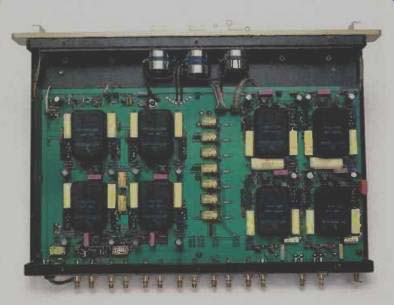
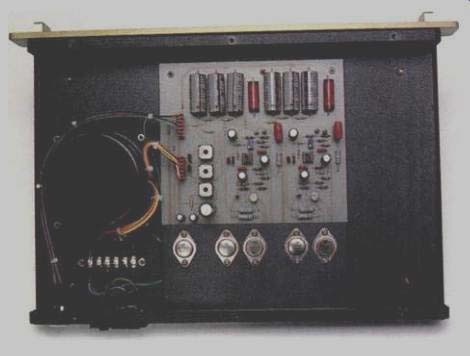
Taking a closer look at the Coherence One preamp first, it can be seen in the photo that most of the interior space of the unit is taken up by a p.c. board which carries the majority of the parts. The signal in/out connectors are soldered directly to this board. Evident in the photo is the presence of three Penny & Giles rotary controls for left and right balance trim and for main volume. Each channel has four active circuit blocks, two in the phono section and two in the line output section. Related discrete parts surround each module.
An L-shaped bracket bent up to form a front subpanel is mounted to the bottom of the unit and serves as a mount for the three rotary controls on the front panel. This bracket also supports, via standoffs, the p.c. boards on which the touch switches are mounted. The chassis metalwork is straightforward, consisting of a single piece bent up to form the rear panel, bottom, and front subpanel. The top of the front subpanel and rear panel and all side ends are folded over to make half-inch ledges that serve as mounting surfaces for the top cover. A separate piece, bent in the form of a U, forms the top cover. The main chassis pieces appear to be made of aluminum, and the top cover is made of steel for some magnetic shielding. A quarter-inch-thick front dress panel completes the enclosure. Parts quality and general aesthetic beauty of this unit are absolutely first-rate.
The power supply contains a potted toroidal power transformer and a large p.c. board with the main regulator circuitry on it. Five TO-3 power transistors on this board are mounted to a metal heat-sink that is also mounted to the rear panel to channel heat out of the unit. Located on the rear panel is a combination a.c. line plug socket, power switch, and fuse-holder and a seven-pin XLR connector for power connection to the preamp itself. As in the preamp, the top cover is made of steel, whereas the rest of the chassis is aluminum.
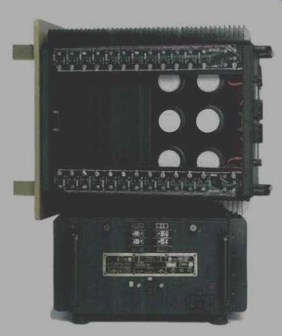
Looking inside the Model 7 is an experience in seeing how far the combination of functionality and beauty can be taken. The enclosure for the power transformer takes up about half of the interior area (as viewed from the top) and measures an awesome 6 x 9 x 9 inches. The remainder of the interior is taken up by a subchassis which supports the six main 22,000-uF, 100-V filter capacitors.
The main signal circuitry is located on a vertical motherboard inside the rear panel, which carries the plug-in frontend module. The location of this board allows short, direct connections to the input jacks and the output stages while keeping the front-end as far as possible from the power transformers. The large, epoxy-encapsulated front-end module also carries the power-supply regulation and driver circuits.
The Model 7's output stage consists of 12 pairs of output devices and one pair of drivers, all metal-cased TO-3 devices. Physically, the output stage is split into two sections that correspond to the positive and negative half-waves.
Each half has its own heat-sink on one side of the amplifier. A nickel-plated copper piece for each side of the amplifier is bent to form a horizontal ledge measuring 2 3/4 x 18 inches; the output devices and driver for each half of the output stage are mounted to these ledges. The main vertically oriented area of each copper piece is bolted to the inside of the heat-sink. This construction really helps transfer the device heat to the entire area of the heat-sinks. Printed circuit boards on top of these pieces interconnect the driver and output devices. Supply traces on the p.c. boards are reinforced with heavy bus wire, and output transistors are bused together via a 10-gauge wire which directly feeds the output connectors.
A fourth p.c. board, mounted to the inside surface of the left heat-sink, carries a potted toroidal power transformer, rectifiers, filter capacitors, regulator circuitry for the two bipolar power supplies that feed the front-end module, and a fifth supply for relay circuitry. Other functions on this board include detection circuitry for the amplifier's protective circuits, soft turn-on and turn-off circuitry (including the associated power resistors and relays, and the main rectifier bridge for the output stage supply; this bridge has its metal surface bolted to the heat-sink). A barrier strip for setting main power-transformer primary strapping for different voltages is mounted on the side of the transformer. A nice touch on this board is a set of five LEDs that show when the five auxiliary power supplies are operating properly.
Parts quality of the Coherence One and Model 7 appears to be of the highest order, and construction and build quality are first-rate, as beautiful as I've ever seen.
Circuit Description
The block diagram of the Coherence One Series II preamplifier, Fig. 1, shows the four encapsulated, plug-in gain blocks per channel. Adjacent to each module are local power-supply regulators and other passive components. In the phono preamp section, the first block has a gain of about 46 dB at 1 kHz. In contrast to all the other gain modules in the preamp and power amp, this block has a non-differential, or single-device, first-stage topology which always yields the lowest possible referred input noise. A number of high-transconductance N-channel FETs are paralleled here, with the entire stage drawing about 30 mA of quiescent current-definitely the way to get low noise with low source impedances. The output of the second stage of this gain block has a very high dynamic output impedance, which means that the circuit's gain can be determined by the value of a shunt resistor across the output. Further, the correct value of shunt capacitance across this resistor will cause a high-frequency roll-off at 2,120 Hz, as required for the final part of the RIAA equalization curve. This network is lightly loaded by the following gain of one buffer, which in turn drives another passive RC network that generates the bass boost for the RIAA curve. The second gain block in the phono circuit is a flat post amplifier having 35 dB of gain.
With an insertion loss at 1 kHz of about-20 dB in the passive bass-boost network and the combined active gain of 81 dB, we end up with a net phono preamp gain of 61 dB, which is appropriate for moving-coil pickups of low to medium gain. Moving-magnet cartridges are accommodated by exchanging the first gain blocks in each channel with optional low-gain nodules.
The cartridge loading system for the phono input is unusual and interesting. By moving one end of a red jumper in each channel of the preamp, you can select variable load, a user-set fixed load, or a 47-kilohm load. In its variable-load position, the load-select jumper bridges the phono input with a variable resistor which can be adjusted for any value from 0 to 200 ohms; this resistor is adjusted through a hole in the rear panel by using a special adjustment tool supplied with the preamp. To use the fixed-load position, you must not only set the jumper but solder in a resistor of whatever value is desired. In the last jumper position, the input is bridged by an internal 47-kilohm load resistor.
The manufacturer suggests that you use the variable load only to determine the loading which sounds best with your cartridge, after which the fixed-load position should be used, with an appropriate resistor (preferably a high-quality metal-film type) soldered to the internal terminals.
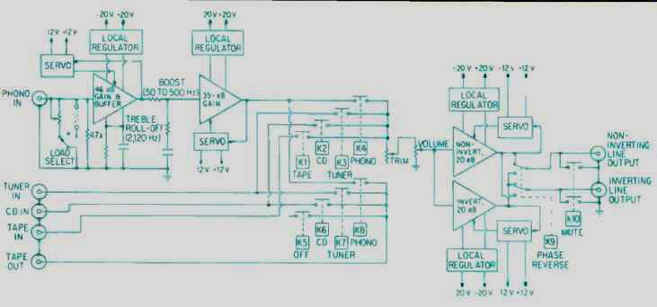
Fig. 1--Block diagram of the Coherence One Series II preamplifier signal circuitry.
As Fig. 1 shows, the 47-kilohm resistor remains in the circuit for all positions of the load-select jumper. It is therefore possible to add capacitance to the load for a moving magnet cartridge (with the appropriate low-gain blocks in place) by soldering a high-quality capacitor to the internal terminals and setting the jumper to the fixed-load position.
Each gain block in the Coherence One has a pair of local voltage regulators that, according to the manufacturer, do not use negative feedback. Technically it is not possible to have a regulator with no negative feedback. A regulator, as such, usually senses the output and compares it to a reference, and the difference drives a series-pass element in order to maintain output at the desired value. Another common type of regulator, however, is an emitter-follower with a regulated source (such as a zener diode) for its base input.
This type of regulator has no obvious feedback, as it doesn't sample the output and compare it to the input, but the topology has its own inherent feedback-100% current feedback, to be precise. In the Jeff Rowland regulators, the follower is made up of a compound-connected pair of transistors of opposite sex, a different topology than the usual emitter-follower configuration. We will see this compound connection in a number of other places as we go through the circuitry.
Signal selection in the Coherence One is accomplished by relay switching. Front-panel switches feed into the pushbutton logic, which ultimately applies power to the appropriate relay coils to make the appropriate signal connections.
There are two selector systems, one for what is listened to and the other for what is sent to tape out for recording or other signal processing. The problem of how to prevent input-to-output feedback in connected tape recorders or external processors is neatly solved here by not connecting the tape-in signal to the tape-out circuitry at all.
Whatever signal is selected passes into the balance-trim potentiometers for each channel, each of which is hooked up as a rheostat in series with the volume control. With this arrangement, the high-level instant impedance changes as the balance trims are changed. The highest input impedance (about 20 kilohms) is obtained with the balance trims almost fully counterclockwise; rotating either trim control fully counterclockwise will completely disconnect the respective channel's signal through a switch.
Output from the volume control feeds two separate output amplifier modules, one noninverting and one inverting. Input impedance for both modules is high, since no feedback returns to the input circuitry-there is no audio signal feedback at all. The circuit transfer characteristics are the same for these modules' positive and negative inputs, so any even harmonics the modules generate should largely cancel in the differential output. A double-pole, double-throw relay connection at the output of these modules permits both output phases to be inverted by the "Phase Rev" switch on the front panel.
Signal circuitry inside the modules (with the exception of the phono input circuit) is, in principle, like that of the power amplifier's front-end, which can be seen in Fig. 2A and will be further explained later. Servo circuitry around each module block keeps d.c. offset low at each output/input coupling point.
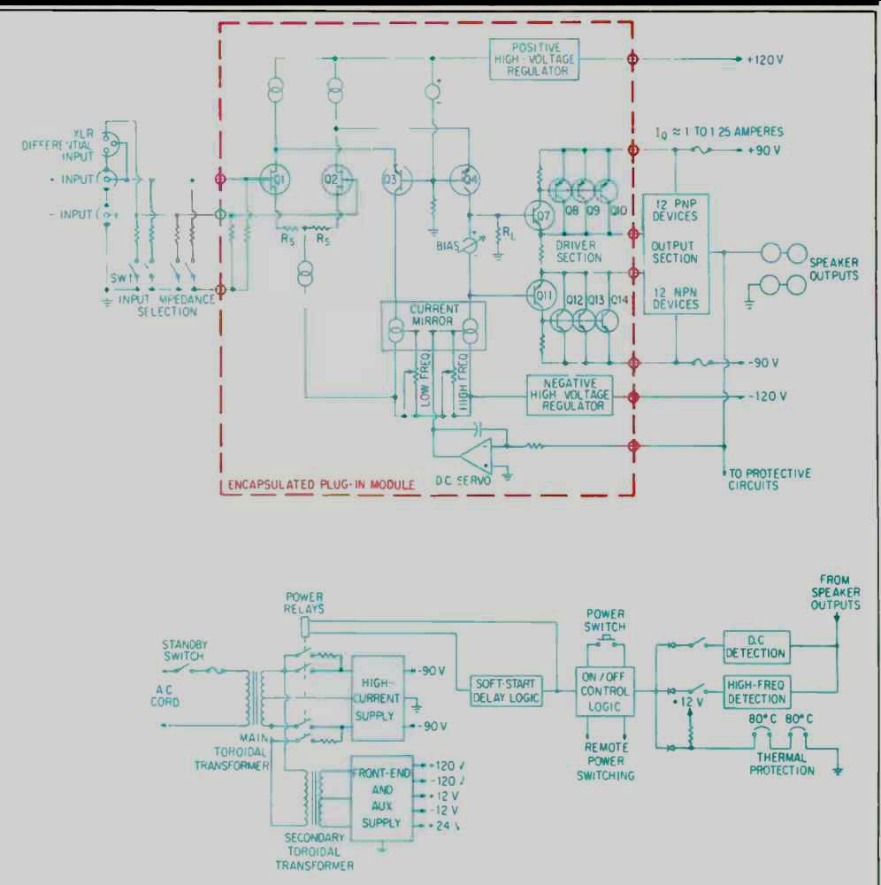
Fig. 2A--Block diagram of the Model 7 amplifier signal circuitry. The pots
marked "Low Freq." and "High Freq." adjust common-mode
rejection; la is quiescent current.
Fig. 2B--Block diagram of the Model 7 power supply.
The external power supply produces one bipolar supply of +20 V and-20 V for the main signal circuitry and a + 12 V supply to power the servo op-amps and switching relays.
For the servo op-amps,-12 V is derived from the incoming-20 V on the preamp board by a three-terminal -12 V regulator. The technique used for the 20-V supplies is interesting in that the two circuits are the same, using same-sex devices in the same circuit positions. Separate transformer secondary windings feed full-wave capacitor-input filters and then feed the regulator circuits. The two circuits are stacked up on each other or connected in series at the outputs, with the midpoint between them being the common point for the load circuitry. This is good, in that the two supplies have a much better chance of sounding the same when they are the same, as opposed to the usual practice of using complementary devices in two complementary mirror image circuits which are then fed from one transformer secondary winding.
A brief comment or two on how the Series II version of the preamp differs from the original is probably appropriate at this point. The servo op-amps have been removed from their sockets and placed inside new modules. Main regulated power-supply voltages have been reduced from ±50 V to ±20 V; consequently, the Series II version runs considerably cooler. The a.c. line draw is down to about 0.32 ampere as compared to 0.52 ampere. With a considerably higher supply voltage for the module, the original version of the preamp could put out more voltage at the onset of clipping, both at the main output and the phono output. However, the Series II can drive 600-ohm loads to a higher level than the original. I'm not aware of what specific changes have been made in the line-amp modules, other than the inclusion of the d.c. offset servos. The earlier phono circuit had three different user-selectable gain settings to allow the use of moving-coil and moving-magnet pickups. As mentioned, the Series II phono circuitry's gain is set by exchanging front-end modules; the unit I tested was optimized for moving-coil pickups of low to medium gain. The gain distribution between the three circuit blocks constituting the phono circuitry, and the method of high-frequency roll-off, were different in the Series I.
Turning our attention to the circuitry of the Model 7 power amp, Fig. 2A offers a simplified schematic/block diagram of the beast. As can be seen, the input circuit is a junction-FET differential amplifier in which both inputs are brought out to the input connectors. The input impedance selector operates on both input polarities, and it shunts the normally high input impedance of 100 kilohms down to two selected lower values. The reason for offering this lower input impedance, by the way, is the manufacturer's belief that lower load impedance makes interconnect cables sound better by virtue of their being terminated with a resistance closer to their characteristic impedance.
Output of the first stage is direct-coupled to the emitters of a PNP bipolar differential second stage. This set of devices is connected in the common-base mode, providing low input and high output impedances. This is an interesting topology-a sort of inverse cascode arrangement. Usually a cascode first stage couples into the cathode, emitter, or source of the upper device of the cascode, and that device is the same sex as the lower device. At any rate, the collectors of this second stage are coupled down into a current-mirror circuit which sums both differential phases into the collector circuit of 04, producing a signal that drives the output buffer circuit. This current-mirror circuit comprises five transistors and has provision for trimming the circuit's common-mode rejection over and beyond the audio frequency range. In this circuit, RL loads down the output of the last voltage amplifier circuit and, in conjunction with Rs, sets the voltage gain of the entire amplifier. These critical resistors, Rs and RL, are Vishay "bulk-metal" precision types for ensuring maximum signal integrity (and are said to cost about $5 apiece). A bias-spreading regulator performs the usual functions of biasing the buffer amplifier and the following output stage to the desired quiescent currents, and of providing temperature compensation to keep these currents stable.
Another unusual and innovative feature of this circuit is the way the d.c. output offset servo operates by controlling the current mirror rather than the more common method of affecting the input differential amplifier. This puts the output offset-correction servo more truly out of the signal circuit than is usual.
Another example of using compound-connected devices in a unity-gain follower can be found in the driver circuit.
This circuit provides low driving impedance for the output stage, which itself is also topologically just like the driver circuit shown, a compound circuit with unity voltage gain. Of course, the number of output devices is a bit greater-like, 12 pairs-and the outputs and driver are all TO-3 heat-sink mounted types.
Apparent in Fig. 2A is the absence of any overall loop feedback in the Model 7. As can be seen, the front-end circuit is powered by local "feedbackless" regulators, as described in the preamp circuitry. Also, as previously mentioned, the circuit topology of the preamp gain blocks is very much like this power amplifier's front-end module.
The main power-supply circuit in the Model 7 (Fig. 2B) is somewhat different than that of your usual power amplifier.
For example, the main power transformer is always on when the unit is plugged in and the rear-panel power switch is turned on-the normal mode of operation in the Model 7.
Connected off the main secondary winding in the main power transformer is the primary of another, auxiliary transformer. Its purpose is to continuously power the front-end module, whether the amplifier is powered up for use or not.
Control of the amplifier's operating state is by the front-panel pushbutton. When normal amplifier operation is desired, this pushbutton is pressed, initiating the soft start-up sequence.
The energizing of this relay coil closes a pair of relay contacts, which connect the main power transformer's secondary to the rectifier bridge and filter capacitors through two series power resistors. These resistors reduce a.c. inrush current and preserve power switch contacts while bringing the output stage supply up to some large fraction of its normal voltage. After an appropriate interval of a few seconds, another relay coil is energized which, in effect, shorts out these series resistors and applies full energy to the main power supply. Since the front-end is always powered up, there is no turn-on/turn-off surge, and the amp's sonic warm-up time is greatly reduced. Good trick! This on/off control logic is also influenced by the dictates of the amplifier output d.c. and excess high-frequency detector circuits and by the state of the thermal sensors on the output stage's heat-sinks. If any of these circuits and sensors detect conditions that are considered unsafe, the on/off logic circuitry shuts off the power supply by opening the control relays. I might mention that this scheme of controlling and turning on the amp could have been done in the primary circuit of the main transformer, with the auxiliary transformer always powered from the incoming a.c. line.
Because this approach would not pass some of the world's tougher safety standards, the way described is the more intelligent way to go.
All in all, the circuitry in the two Jeff Rowland Design Group components looked at here is very original and innovative. Let's see how these units performed.
Measurements

Fig. 3-RIAA equalization error of Coherence One Series II.
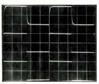
Fig. 4-Response to square waves, with instrument load, through the phono section
of the Coherence One Series II for, top to bottom, 10 kHz, 1 kHz, and 40
Hz. (Scales: Vertical, 0.5 V/div.; horizontal, top to bottom, 20 µS, 200
µS, and 5 mS per div.)
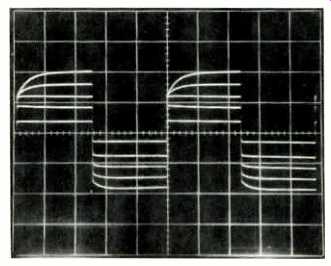
Fig. 5-Overload test of phono circuit, using pre equalized 1-kHz square waves
at increasing output levels; see text. (Vertical scale: 2 V/div.)
Table I--Gain and sensitivity for Jeff Rowland Coherence One Series II preamp. Volume, balance, and trim pots were all set to their full clockwise positions.
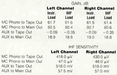
Table II--Noise of MC phono section, referred to input, and IHF S/N ratio in MC mode, vs. source impedance.
Table III--MC phono overload vs. frequency. Results were about the same for instrument or IHF loading; clipping occurred in the positive half-wave first.
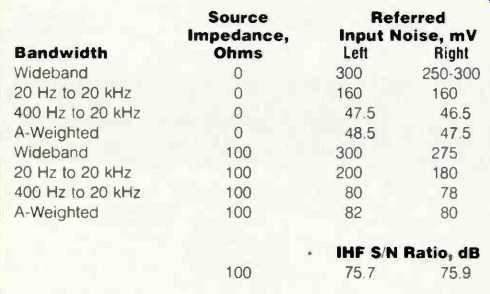
Preamp gains and sensitivities are enumerated in Table I. Phono equalization error is shown in Fig. 3. (The phono input in the preamp I tested was, you'll recall, MC only.) The equalization is, in general, very accurate, with a very slight emphasis in the upper midrange. Related to this frequency response are 'scope photos of pre-equalized square waves going through the phono preamp (Fig. 4). Table II shows both noise, referred to input, and IHF signal-to-noise ratios for the phono section. Noise levels are quite good with the 0-ohm source when measured with A weighting or with a bandwidth of 400 Hz to 20 kHz. Since most good MC pickups are closer to 0 than to 100 ohms in impedance, actual system S/N with this preamp should be excellent.
Crosstalk between channels for the phono circuit was outstanding--down by more than 80 dB at frequencies up to 400 Hz, increasing to about -78 dB at 20 kHz, and quite symmetrical in both directions. Since the amount was so far down at high frequencies, it was difficult to determine the phase of the interchannel crosstalk, so I'll have to call it indeterminate.
Phono overload versus frequency is listed in Table III for both channels. As can be seen, the left channel's performance was slightly inferior to the right channel's, in that the output attainable in the last octave of the audio range was lower for the left channel. The results shown are for instrument loading, as IHF loading (10 kilohms in parallel with 1,000 pF) only changed the input levels for output overload by 1% to 2%. This circuit behaved in a near ideal fashion, as its output clipping level was constant with frequency. The output overload point for this circuit was at the onset of clipping on the positive half-cycle of the output waveform.
However, some d.c. level shifting took place as I varied the input signal amplitude in the last octave of the audio range.
Pushing the phono circuit to higher output levels with a pre equalized 1-kHz square wave resulted in some high-frequency compression and asymmetrical behavior (Fig. 5). As phono circuits go, this one behaved pretty well on this test. The input acceptance, 9 mV at 1 kHz, was more than 20 dB higher than most good MC pickups will put out at standard cutting level (3.54 cm/S per channel, 5 cm/S lateral velocity). Furthermore, this margin of more than 20 dB extended over the whole frequency range. My criteria for input acceptance are certainly met in this design.
Phono circuit THD + N is shown as a function of output voltage for two test frequencies, 1 and 20 kHz, in Fig. 6. Distortion at lower frequencies was lower than shown for 1 kHz, but hum pickup in my setup prevented accurate measurement of this.
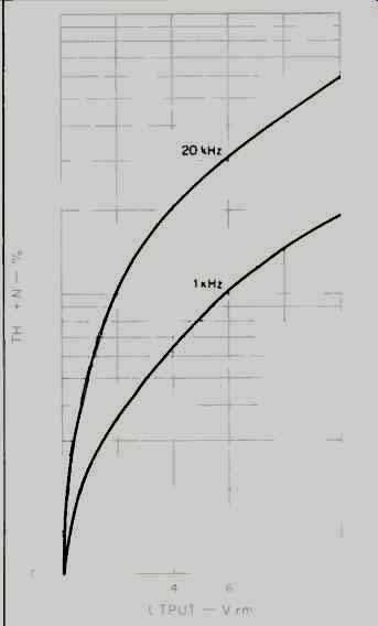
Fig. 6--THD + N of phono section as a function of output voltage, for two
frequencies.
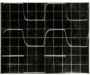
Fig. 7--Response to square waves through line inputs for, top to bottom,
200 kHz with instrument load, 200 kHz with IHF load, and 20 Hz with instrument
or IHF load. (Scales: Vertical, 5 V/div.; horizontal, 1 µS/div. for 200
kHz, 10 mS/div. for 20 Hz).
In the line amplifier, rise- and fall-times at ±5 V output were tested as a function of balance and volume control settings, for both instrument and IHF loading. With volume and balance both at maximum, rise- and fall-times were 240 and 480 nS for instrument and IHF loading, respectively.
With volume at maximum and the channel trim turned down for a 6-dB reduction in gain, rise- and fall-times lengthened to 680 and 800 nS for instrument and IHF loads. With the channel trim at maximum and volume turned down 6 dB, rise- and fall-times were 300 and 480 nS with the respective loads. Both positive and negative output phases gave essentially identical results.
Oscilloscope photos of the line amp's square-wave performance are shown in Fig. 7. The top trace is for a blistering 200 kHz, with instrument loading at ±5 V output. In the middle trace, the effect of the 1,000-pF capacitance of the IHF load shows in the lengthening of the rise- and fall-times. (No slouch for speed, the Coherence One's output amp!) The excellent low-frequency response is clearly seen in the 20-Hz trace (bottom); tilt is virtually absent here.
In setting up to measure volume control tracking, I wondered why the gains of the output amp were different when both gain trim pots were turned counterclockwise. I think the intention is for the two trim controls to be fully clockwise in normal operation and, if balancing needs to be done, for the lower channel's trim pot to be turned down.
I had reason to use the preamp with its trim controls in the counterclockwise position. This made the preamp's line level input impedance about twice as high as it would otherwise be, which reduced bass attenuation and loaded my tube CD player or other tube sources less.
With both the trim controls clockwise, the gains of the two channels were virtually identical. With them both counterclockwise, left- and right-channel gains were down 6.7 and 5.4 dB, respectively. This is too much channel imbalance for equal control position, in my opinion. I measured the resistance value of the balance pots and both gangs of the dual volume control and discovered what I consider to be an excessive resistance variation for controls which are otherwise fabulous in quality. For the trim controls, I measured 10.38 kilohms for the left-channel pot and 8.8 kilohms for the right. For the volume controls, I measured 8.73 kilohms for the left channel and 9.96 kilohms for the right. This distribution of resistances completely accounts for the difference in channel attenuation with the balance controls turned down.
With the trim controls fully clockwise, tracking between the left- and right-channel halves of the volume control was within 1 dB at gain settings from full clockwise down to 60 dB of attenuation. Below-60 dB, the attenuations diverged, reaching a difference of 3.6 dB when the control was turned down to-75 dB. Harmonic distortion plus noise was measured for both output phases at output voltages of 1, 3, and 5 V rms. IHF loading didn't materially affect the results. In general, distortion was low and simple in nature, and was 0.01% or less for output voltages of less than 3 V. Distortion rose with frequency above about 5 kHz. At 5 V out, distortion was in the range of 0.01% to 0.03%.
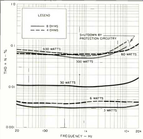
Fig. 8--THD + N of Model 7 amplifier as a function of frequency and power
output for 8and 4-ohm loads.
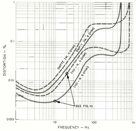
Fig. 9--SMPTE IM and THD + N vs. power for 8- and 4-ohm loads.
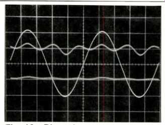
Fig. 10--Distortion residues and 1-kHz signal. For 10 watts into 8 ohms
(bottom trace), THD measured 0.003%; for 20 watts into 4 ohms (top trace),
distortion was 0.015%.
THD + N is for 1-kHz signal. Distortion residues at circled points are shown in Fig. 10.
Onset of clipping was about 10 V for instrument or IHF loading. With a 600-ohm load, clipping started at about 8 V. The Coherence One could put out 3.8 V into 100-ohm loads before clipping set in. The aforementioned clipping levels are per output phase; each figure cited would be doubled when the preamp is connected for balanced output, with the same load impedance between each half of the output and ground. To see how well even-order distortion cancelled out in the differential, or balanced, output, I first measured the performance of both the positive and negative unbalanced outputs at 1 kHz and 20 kHz. Then I hooked up both output jacks in a balanced configuration and measured the distortion at the same two frequencies. The results in Table IV show that a good part of the individual-phase distortion cancels out in the balanced connection.
Interchannel separation was better than 90 dB from 20 to 400 Hz, decreasing to 88.6 dB at 1 kHz, 75 dB at 5 kHz, and 63 dB at 20 kHz. Results were virtually identical in the two directions. This is very good behavior.
Lastly, referred input noise was measured for both phase outputs and for both channels (Table V). Noise did not vary much as the volume and balance controls were rotated away from maximum by perhaps 0.5 to 1 dB. A final comment on the preamp. Its main power-supply regulators held their output voltage, down to about 100 V a.c. line input.
Voltage gain of the Model 7 amplifier was 20.8 x , or 26.4 dB, with the positive or negative input fed. If fed a balanced signal, the differential gain would be the same, provided that the signal between input phases were the same as the input signal level when fed an unbalanced signal.
Total harmonic distortion plus noise as a function of frequency, power, and load is shown in Fig. 8. Figure 9 shows 1-kHz THD + N and SMPTE-IM distortion as functions of power and load. The Model 7's output stage dissipates a lot of power at idle-the a.c. line draw is about 4 amperes. With 8-ohm loads, the line draw stays constant up to 50 to 60 watts out. Beyond this general power range, the output stage reverts to Class AB, with the output devices starting to cut off for an increasing part of the signal cycle. Distortion generally starts to rise in any amplifier when the output stage goes from Class-A to Class-AB operation. This is because the gain in each half-cycle decreases when the opposite device cuts off and no longer contributes to the output movement. Of note with the Model 7 is the fact that this transition occurs at a high power level, so that the amplifier is in Class-A mode during most music listening and just the peaks reach through the transition. Distortion products for this design are mostly odd-order, as can be seen in Fig. 10, which shows 1-kHz THD residue for 10 watts into 8 ohms and 20 watts into 4 ohms. The predominance of odd-order distortion products shows that the circuit's symmetry in handling the positive and negative half-cycles of the signal is good, as the even harmonics are mostly balanced out. The Model 7's distortion stays reasonably constant across the audio range; it does not rise much at high frequencies, as it does in most other power amplifiers. This constancy is a desirable characteristic.
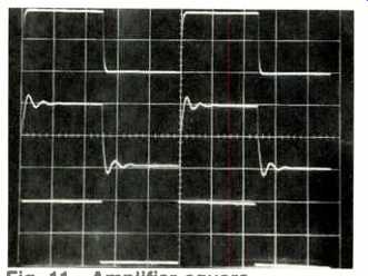
Fig. 11--Amplifier square wave response. Top trace is 10 kHz with 8-ohm
load, middle trace is 10 kHz with 2-1.i.F capacitance across the 8-ohm load,
and bottom trace is 40 Hz into 8 ohms. (Scales: Vertical, 5 V/div.; horizontal,
20 µS/div for 10 kHz, 5 mS/div. for 40 Hz.)
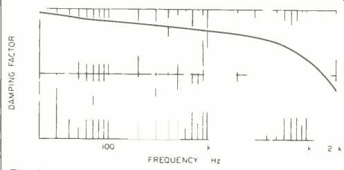
Fig. 12--Damping factor vs. frequency for 8-ohm load.
Table IV--Distortion comparison of Coherence One line amp outputs in unbalanced and balanced modes; see text.

Table V--Line-amp section noise of Coherence One, and IHF S/N ratio, for
unbalanced operation. Volume and balance trims were set to maximum clockwise
positions.
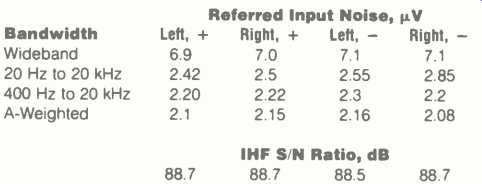
Table VI--Output noise of Jeff Rowland Model 7 mono amplifier with a source
impedance of 1 kilohm. The IHF S/N ratio, with the same source impedance,
was 91.6 dB.

The frequency response at 2.83 V out (corresponding to 1 watt into 8 ohms) was very independent of load, from open circuit down to 4 ohms. This is due to the lack of an output buffering RL network and to the low impedance of the output stage at 100 kHz. Response at the high-frequency end was down about 0.7 dB at 100 kHz. Low-frequency response was still at reference level at 10 Hz. Related to frequency response is square-wave performance (Fig. 11). In the top trace, the frequency is 10 kHz with an 8-ohm load.
A 2-uF capacitor has been shunted across the 8-ohm load in the middle trace. Excellent low-frequency extension is seen in the bottom trace, which is at 40 Hz.
Damping factor versus frequency, referred to an 8-ohm load, is plotted in Fig. 12. As can be seen, damping factor is relatively high and doesn't fall off very much with increasing frequency, as it does in most other power amps. What is interesting is having so high a damping factor in an output stage without overall loop feedback. I don't understand why this curve slopes gently over much of the audio range without being flat at any point, but this is a designer's puzzle rather than a performance problem.
The Model 7's output noise and IHF S/N ratio are listed in Table VI. In the wideband mode and with the bandwidth of 20 Hz to 20 kHz, noise is dominated by 120-Hz ripple of the capacitor-input type. The amount of this ripple-type hum is satisfactorily low, however, and is not audible.
To measure common-mode rejection, I used a test signal whose amplitude produced 10 V output when fed to either input, then measured how far down the output was when both inputs were fed with the same signal. From 20 Hz to 1 kHz, the output was down in the noise, at 86 dB; it increased to -85 dB at 7 kHz and to -81 dB at 20 kHz. These are good numbers for this test, especially at 20 kHz.
Tests of dynamic and clipping headroom yield some pretty impressive numbers for the Model 7. Rated power is 350 watts into 8 ohms and 700 watts into 4 ohms. For dynamic power, I obtained 484 and 925 watts into the respective loads, for dynamic headroom figures of 1.4 and 1.2 dB, respectively. Clipping occurred at 470 and 840 watts, for clipping headroom values of 1.3 and 0.8 dB. The amp was able to deliver ± 78 amperes into a 1-ohm load at the clipping point. All these tests were for a constant 120 V a.c. line. These Model 7s are very powerful beasties indeed! Use and
Listening Tests
Equipment used to evaluate the Model 7s and the Coherence One Series II included as signal sources an Oracle turntable fitted with a Well Tempered arm and a Spectral Audio MCR-1 Select cartridge, a Nakamichi 250 cassette deck, a Technics 1500 reel-to-reel recorder, a California Audio Labs Tempest CD player, and a Nakamichi ST-7 tuner. Other preamps on hand during the testing were a Vendetta Research SCP 2A, the Mark Levinson No. 25 with the No. 26 phono section, and my reference preamp, which combines a tube phono stage with a selector switch and a passive, switched attenuator (think of it as a preamp without an active line stage). Other power amps used were a pair of EAR 519s and a Counterpoint SA-20. All of the listening was done through Siefert Research Magnum III speakers and Stax SR-X/Mk3 'phones using a Stax SRD-7 Pro adaptor.
As I usually do when reviewing equipment, I tried different combinations of gear at different times and got various results. I tried the Jeff Rowland preamp with different amps and the Model 7 amps with several preamps. I also had the opportunity to listen to two Coherence Ones, the original version and the Series II. If I had never heard the amp and preamp hooked up together, I might have had the following comments on the separate pieces: The amplifier has an ease of presentation that is probably a partial result of its being so powerful but is also due to the amp's circuitry and to the way the unit is built. Soundstaging is very good; tonal balance is a bit on the soft side for upper mid and high frequencies, which appeals to my listening biases. The preamp, however especially the original version-is not that exciting in my setup. It is musical and smooth sounding but doesn't quite sound as convincingly real as my own reference tube preamp or the Vendetta SCP 2A. In these regards, I think the Series II preamp is substantially better than the original.
When the Jeff Rowland units are hooked up as a pair, things get much better. Playing CDs through the combination produces a magnificent bass that sounds easy and extended-definitely very nice! The rest of the range sounds very good too, with good space, dimensionality, depth, and tonality. Records sound good and musically involving with the combination.
The preceding comments are based on using my usual 20-foot interconnect cables. I then tried a pair of 6-meter AudioQuest Live Wire Lapis cables that were provided by Audio for use with balanced equipment; these cables have a pair of RCA male phono plugs on one end and an XLR connector on the other. I heard a subtle improvement in the sound with these cables, and all subsequent listening was done with them.
Jeff Rowland has a notion that loading down interconnect cables with lower impedances than normal power amplifiers present helps the sound. I gather he suspects that by driving greater current through the wire (due to the low load impedance), possible nonlinearities such as magnetostriction and dielectric absorption in the cable materials might become a lower percentage of the total signal. At any rate, the Coherence One Series II that I reviewed has "build-out" resistors in series with its output stage, so its output resistance per phase was on the order of 150 ohms. Mr. Rowland suggested that I load down the receiving end of the cable with 150 ohms per phase and see if I could hear a difference in the sound after raising the volume control's setting to overcome the approximate 6-dB loss in level caused by this loading. Since the Model 7s have RCA jacks for each input phase as well as a balanced XLR connector, this was easy to do. I soldered 150-ohm, 1/4-watt, metal-film resistors into four high-quality male RCA plugs and inserted them into the positive and negative RCA jacks, while feeding the signal in through the XLR connector. I'll swear that the load resistors made the system sound better. Resolution seemed to improve, and the irritation I had felt on one particular recording seemed to decrease very noticeably! One might wonder what had changed: The characteristics of the interconnect cable or the sound of the preamp output amplifiers with the lower impedance loading? Further research would be needed to find out. Suffice it to say, I liked what happened better with the low-impedance loading. Loading preamps down with hundreds of ohms is not generally recommended, as most preamps can't begin to drive such low impedances. The Jeff Rowland Coherence One, however, had no trouble driving many volts into this load at low distortion.
Summing up, I found the sound of the Jeff Rowland equipment to be very good. I certainly enjoyed listening to the Coherence One Series II and the Model 7 and having their beauty grace my environs. For those with the wherewithal to consider equipment in this class, I certainly recommend giving the Jeff Rowland Design Group's components a serious audition.
-Bascom H. King
(Audio magazine, Apr. 1990)
Also see:
Sansui Model CA-F1 Preamplifier (Jun. 1980)
= = = =