by Martin Clifford
RADIO WAVES are far from genteel, for they cannot be so and survive. But the strongest signal isn't always the most preferable, and so we now have tuners capable of reaching out and succoring those emaciated signals that, a technical decade ago, would have perished.
That ability of a tuner to respond to the weakened remnant of a signal is called sensitivity, a good word, a pleasant word, but a most unfortunate one since it implies a certain sensibility and kindness on our part. Nothing of the sort, of course. We want tuners having high sensitivities to be able to pick up weak signals for the sole practical reason that those signals may be the ones we want. The desideratum of a signal isn't its strength or ability to survive, but simply a relationship to our own personal wants.
The FM band covers a range of 88 to 107.9 megahertz, a total of almost 20 megahertz. You can realize how wide this band is by comparing it to the AM broadcast band which extends from 535 to 1635 kilohertz, a total of 1100 kilohertz or 1.1 megahertz. And so the FM band is approximately 20 times as wide as the AM band. Into this FM band playroom are crammed all the broadcast FM stations with each occupying individually much more band space than comparable AM stations.
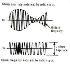
Fig. 1--In AM, the carrier strength, or amplitude, changes during modulation.
With FM, the carrier strength remains unchanged.
AM vs. FM
Per se, audio waves have a very short travel span. If you want to know how far audio waves can travel unassisted, and are willing to experiment in the name of science, try shouting out of your bedroom window in the quiet early morning hours. If you can avoid capture and confinement, you will have learned that the distance covered by your voice is a few hundred yards, if that. To overcome this limitation, at the broadcast station the audio signal is electronically loaded on another, much higher frequency wave, called a carrier for very obvious reasons. (The carrier is the assigned frequency in the FM band.) The loading process is called modulation, whether for AM or FM (Fig. 1). The reverse process in the tuner, that of discarding the carrier and recovering the original audio signal, is demodulation. Amplitude modulation, or AM, changes the strength or amplitude of the carrier wave; frequency modulation changes its frequency.
At the Antenna
Just as eating and breathing are our two fundamental survival processes, so too are sensitivity and selectivity the basic functions of all tuners. While these are inherent to the tuner, we can consider the antenna as an extension, a sort of probe stuck into the murky ocean of radio signals. The first steps toward selectivity are taken by the antenna, for it is broadly resonant to the FM band, and, hopefully, rejects all other signals. But, inducing voltages across the antenna are not only FM signals, but all other radio signals as well-tv signals, communications signals, and electrical noise. Some of these signals, outside the FM band, are more or less successfully rejected by the antenna, depending on the antenna itself, its number of directors and reflectors, and the strength of a particular signal. The whole polyglot assortment of those that remain are given the opportunity of entering the FM tuner via the transmission line, either twin lead or coaxial cable, acting as the connecting link between antenna and tuner input.
The sensitivity of a tuner is a measure of its ability to be activated by the signals proffered by the antenna. It can also be described as the minimum signal to which the tuner will respond and still produce a satisfactory output.
Sensitivity is measured in terms of microvolts, or millionths of a volt, per meter. A meter is 3.28 feet, and so an antenna of this length, producing 6 microvolts of signal, supplies 6 microvolts per meter. Whether the receiver twill respond to such a small signal is another matter, for it depends on the receiver's sensitivity. A receiver with a sensitivity of 6 microvolts conceivably could; one with a sensitivity of only 10 microvolts will not. Receiver sensitivity is indicated on manufacturers' spec sheets in microvolts; the smaller the figure, the better. However, these numbers refer to the minimum antenna signal which the tuner can convert into a satisfactory sound signal. By itself, the sensitivity figure is meaningless, for if the signal is weak, it may be overwhelmed by electrical noise. The ratio of signal to noise, written as S/N, is the ratio in dB between a 400 Hz fully modulated signal and the noise component. 60 dB means that the signal is 1,000 times stronger than the noise. The higher the value, the better. 50 dB is about the minimum requirement for hi-fi.
It is also possible, of course, for two signals to be close to or to occupy the same frequency, particularly if the originating stations are widely separated geographically. The ability of the tuner to suppress the weaker of the two while receiving only the stronger, is called the capture ratio.
Capture ratio is also related to the tuner's suppression of random noise.
On spec sheets, capture ratio is given in dB, and the smaller the value, the better. 4 to 5 dB is usually adequate.
The tuner must not only be able to respond to signals, but having done so, must separate the one desired signal from all the others fighting for attention. This ability is called the tuner's selectivity (Fig. 2). Expressed in dB, higher values are better. 50 dB is generally regarded as sufficient.
The Front End
The FM antenna not only responds to a tremendous number of signals simultaneously, but delivers them all to the input of the tuner, via the transmission line. The tuner input, then, is a scene of chaos, for one, and only one signal must be permitted through. This is an impossible task and since it is impossible, just isn't done. However, the process of selectivity, initially started in a rather general way by the antenna, is continued here.
The first processing department reached by the signals is the radio-frequency amplifier (Fig. 3) consisting of one or more tuned circuits. Better grade FM tuners may have between three and five tuned circuits; the more, the better and the more, the more it costs.
The selectivity process is accompanied by amplification, with the signal successively strengthened by a series of solid-state amplifiers, often special types of transistors called FETS, or field-effect transistors, especially selected for their ability to behave well at the high FM frequencies, supplying sensitivity and amplification with minimum fuss and noise.
The various RF amplifier stages are part of a larger circuit carrying the general name of front end. Included in the front end is an AC generator, a circuit which produces a high-frequency signal. Known as a local oscillator, its output is made to mix or beat or heterodyne (from which we derive the name-superheterodyne) with the incoming signal. The purpose is to produce a signal having a constant center frequency. For FM tuners and receivers this frequency is 10.7 megahertz. Known as the intermediate frequency, and variously abbreviated as I.F., IF, or if, it enables the tuner to have the tremendous selectivity for which the superheterodyne is noted.
No matter what the frequency of the incoming signal, adjustment of the tuning control on the front of the tuner also adjusts the frequency of the local oscillator. The result is a constant intermediate frequency. Since the intermediate frequency is 10.7 megahertz, it is much lower in frequency than either the incoming signal or that generated by the local oscillator.
The intermediate frequency is a sort of low-frequency carrier, for it now becomes the delivery medium for the sound signal, previously carried by the radio-frequency carrier broadcast by the FM station. Thus, all that has happened to the audio signal is that it has been transferred from one carrier to another, sort of transshipped as it were. However, the intermediate frequency amplifiers all behave as tuned circuits, and so the selectivity process continues here. This is done by a series of filters of very precise electrical dimensions.
The IF section does more than select--although a properly designed IF will do that remarkably well-but it also fulfills a most important function--the elimination of electrical noise.
Specially designed IF circuits, called limiters (Fig. 4), begin to work only when a signal of sufficient strength is present. Electrical noise behaves like an AM signal, a signal characterized by amplitude variations. The IF limiter, as its name implies, promptly guillotines these amplitude excursions, while the FM signal, whose amplitude is constant anyway, emerges unscathed from this electronic decapitation technique.
The muting circuit, usually switch able with a control on the tuner's front panel, has a similar intent. It cancels the noise encountered on unused FM channels, a sort of irritating hiss that can be heard between stations. Since the muting control cancels weak stations along with the noise, it should be turned off or adjusted to a more minimum muting position, if a weak signal is to be received.

Fig. 2--Selectivity characteristic curve.

Fig. 3--Block diagram of FM stereo tuner.

Fig. 4--The limiter cuts off the noise pulses.
Back to Audio
Once a truck has made a delivery, it moves on to become part of a general traffic pattern. Not so with the carrier wave that has successfully transported the audio signal to the antenna, down the transmission line, through the front end, then suffering the indignity of having its original frequency changed to the much lower intermediate frequency. At the output of the I.F. circuits, the audio signal. still cuddled by the carrier (now called the intermediate frequency) is delivered to the demodulator. Here the carrier is summarily dismissed, its efforts from the broadcast station, through space, and through half the circuits of the tuner counting for naught. No gold watch, no encomiums, no pension.
Simply kaput, made so by grounding.
The audio signal, standing alone, deprived of its carrier, is by now a million or more times stronger than when it first met the antenna, and is in the order of about I volt, or more. It is still too weak to drive a speaker system, but it can be heard with a headset.
However, this is the terminal point of the sound, for what we have here is a tuner, a kind of emasculated receiver.
With a receiver, the signal would proceed through a pre-amp, then a, main or power amplifier, finally reaching the speakers. Tuners aren't equipped with pre- or main amps, and so they require these as separate, additional components.
Mono vs Stereo
What has been described so far is the traditional path followed by a monophonic signal. The modern tuner, though, is capable of responding stereophonically. When a station broadcasts in stereo-also called multiplex or MPX-it transmits a subcarrier wave (Fig. 5) alongside the main carrier and separated from it by 38 kilohertz, plus a pilot frequency of half the subcarrier, that is, 19 kilohertz (Fig. 6). In the tuner, a pilot detector recognizes the presence of the 19 khz signal and activates an FM MPX decoder circuit.
In a stereo transmission, the sound is distributed to two channels, a left or L and a right or R channel. In the stereophonic FM broadcast, the main carrier contains the sum of both signals. Sum means addition, and so the sum of both signals is L + R. A mono tuner or receiver will get the L and R channels, treat them as though they were combined, and the speakers will deliver the doubtful pleasure of single channel or mono sound.
If we can have an L + R signal, we can also have the difference between these two. Difference means subtraction, and so L R means the right channel subtracted from the left channel. The subcarrier transports this L R difference signal. In the FM tuner's MPX decoder these two L + R and L R signals are added and subtracted to regain the signal for each channel. (L + R) + (L R)--2L or left channel sound. (L + R) (L R) = 2R or right channel sound.
It appears complicated only if you haven't studied high school elementary algebra for a long time, or if you were never wildly enthusiastic about it to begin with. The point is that a signal can be divided into portions which represent the positioning of an orchestra on stage, hypothetically divided at some approximate center, with the sound from center to left ultimately and hopefully issuing from your left speaker and the sound from center to right, equally hopefully, coming out of your right speaker.
It's a bitter note, but a true one, that everything has its price, and stereo isn't about to establish an exception.
An FM stereo broadcast has only about half the reach of a monophonic program transmitted with the same power. A way to overcome this deficiency is to move to a strong signal area but it is possibly more practical to have a good outside FM antenna and to give the stereo signal a chance for survival by carefully selecting your tuner from among all those that are offered.

Fig. 5--Carrier of FM MPX stereo.

Fig. 6--Spectrum of FM stereo.

Fig. 7--Controls of a quality FM tuner.
Tuner Construction
At one time, FM tuners were made by the `point to point' method. The various parts, resistors, coils, capacitors, and tube sockets were individually mounted and then hand wired. Testing was done after assembly, and so chassis sections sometimes had to be repaired prior to shipping. The more modern and superior technique consists of building tuners in modular form, with each module representing one or more complete circuits. The modular sections are tested prior to main assembly, and again afterward. Modules may contain integrated circuits, called IC's, consisting of elements that are practically invisible. An IC about the size of a postage stamp (or smaller!) may contain several dozen transistors, some forty or fifty capacitors and resistors.
One of the main improvements in the front end was the introduction of the field-effect transistor, characterized by excellent linearity, a high input impedance, good gain and low noise.
Other tuner innovations are the elimination of the variable tuning capacitor and its replacement by semiconductor diodes known as varactors or varactor diodes. These units can be made to behave as capacitors by controlling the voltage that is put across them.
They lend themselves well to automatic scanning of the FM band, so it becomes possible to cover the entire band just by pushing a button, with each station being tuned in precisely, in turn. Some tuners are also available with indicator tubes instead of a tuning scale. These tubes show the frequency in digital form. Other tuners are really posh, containing a miniature oscilloscope tube that lets you adjust your FM antenna for least multipath distortion. Multipath distortion is the unhappy ability of FM waves to bounce from building to building, or other reflecting surfaces, arriving at your antenna by a somewhat devious route.
The various reflections do not all reach your antenna at the same time, producing the somewhat anomalous condition of the same signal fighting with itself. It results-what else-in distortion.
In the IF section, early FM tuners used transformers which required individual adjustment. Vibration would inevitably detune the transformers, causing loss of selectivity and gain.
Modern IF stages use multistage filters, either ceramic or crystal types. Not only do these avoid the detuning problem presented by transformers, but electronically they are much more well-behaved, by allowing a correct band of frequencies to pass through.
Tuner Controls
If the front panel of a tuner looks like the answer to a knob manufacturer's prayer, let it not fret you, for all of the controls are designed to let you have precisely what the name implies-control (Fig. 7). The trend is toward more controls, not less, and that is as it should be. Controls add to the expense of a tuner, but they do let you adjust for all sorts of conditions, all usually bad, inside your home and external to it.
The operation mode is determined by a function selector which can have three or more positions: AM, FM mono; FM auto, and MPX noise filter.
When this control is in the AM position, that is what you will get--AM stations. The FM mono position is for mono reproduction only. This doesn't mean you won't pick up stereo stations, just that the MPX decoder will be deactivated. In the FM auto mode, the tuner automatically switches to FM stereo reception when tuned to an FM MPX broadcast. Finally, when the mode selector is set to MPX noise filter, this adjustment eliminates noise (during FM stereo reception) having a fairly high frequency.

Fig. 8--Signal strength and tuning meters.
Better quality FM tuners have a pair of illuminated meters (Fig. 8) as tuning aids. One is a signal strength while the other is a tuning meter.
The signal strength meter deflects to the right when the station is tuned in and the stronger the received signal, the greater the deflection. You can also use it for making comparison tests of FM antennas and for the best orientation of the antenna. The tuning meter is a center position type and helps in tuning in stations accurately.
Accuracy means the pointer is at its center position when the station is tuned in properly. Some tuners also have a light which glows with the word ‘stereo', possibly to condition you mentally for this kind of listening.
Mental attitude and frame of mind are essential ingredients for the proper enjoyment of music, and for its improper enjoyment as well.

Fig. 9--Linear scales.
Some FM tuners have nonlinear scales with the numbers toward the right getting more and more crowded.
This sometimes requires a Raffles-like dexterity but since not all of us have safe opening or tuning ability, it is better to look for tuners having linear scales (Fig. 9). In addition to the muting switch, upper grade tuners are often equipped with a switch or control called MPX noise filter or hi blend. Its function is to eliminate or at least reduce hissing noise often present in FM stereo programs of insufficient signal strength. As this circuit operates by blending a certain amount of the high sound frequencies of both channels, its use results in a certain loss of stereo channel separation.
Other controls on tuners include output level controls. On better quality tuners these are separate for AM and FM, letting you adjust the tuner's output voltage to match its sound volume with that of other source equipment, such as your turntable or tape deck. It also lets you 'drive' the following pre-amplifier properly--that is, the tuner can deliver the correct amount of signal to let the pre-amp function as it should. Some tuners have an extra pair of tape rec outputs permitting direct tuner-to-tape recording without going through the amplifier.
The tuner may also have an AFC switch, but you should not gauge its presence or absence as an indicator of the quality of the tuner. AFC, an abbreviation for automatic frequency control, helps lock the selected station to the tuning circuits, thus preventing station drift and fluctuation.
Finally, there should be a muting level control to be adjusted for background hiss in the absence of a received signal, so that hiss cannot be heard during the tuning process.
Correct setting of this control does take some little bit of practice since, if the control is advanced too far to the right, station signals may be muted also. With the muting control in its maximum clockwise position you will have absolutely quiet operation of the tuner, something that can more easily be achieved by turning the power switch to its off position, and non-linear FM dial.
Tuner Specs
There isn't that much difference in the front panel appearance of high grade tuners. Actually, you can put some of the bargain-basement types right alongside some of the really superb, more costly tuners, and find it difficult to reconcile the difference in price with the lack of difference in appearance. But in hi fi, quality is more than panel deep. It's what's behind the panel that counts, and so you must rely on the manufacturer's spec sheet and on the manufacturer's reputation.
Some of the important specs, sensitivity. selectivity, signal-to-noise ratio and capture ratio, were described a few paragraphs ago. Other specs include image rejection, spurious response or rejection, AM suppression, FM stereo separation, and output level. Signal images refer to the unhappy predilection of low-grade FM tuners for having the same signal appearing at two or more points on the tuning scale. Only one of these, of course, is the true signal, while the others are images. This situation arises out of the fact that the local oscillator signal, heterodyning with the original source signal, produces not one, but a number of signals.
For instance, suppose we have an incoming signal at 100 MHz. When the tuner is tuned to this signal the local oscillator will be at 110.7 MHz and the required 10.7 will be derived as the difference. But another signal at 10.7 MHz higher than the local oscillator (110.7 plus 10.7 mHz or 121.4 MHz) might also bear with the local oscillator and make itself heard.
True, this particular frequency is outside the FM band but it is used by aircraft and you don't want to hear airline pilots' conversations as a background to your Beethoven or Brubeck! So image rejection is the tuner's ability to suppress these unwanted signals and it is ordinarily expressed in dB, generally somewhere in the middle of the FM band. The higher the value of image rejection, the better.
An image rejection of 90 dB or more is excellent.
There may be other kinds of interference--breakthrough at the 10.7 MHz IF frequency or spurious signals caused by harmonics of the oscillator. Spurious rejection is often specified at a particular frequency, somewhere near the center of the FM band. Spurious rejection of more than 95 dB, at 98 mHz, is a very respectable figure.
AM suppression is still another spec sheet listing, but while its name implies some connection with AM broadcasting, there is no link between the two. In this context, AM (amplitude modulation) means the noise signals radiated by fluorescent fixtures, motors, neon lights, auto ignition systems, etc.
These devices, which would perform much better minding their own business, all act as miniature AM broadcasting stations, not licensed, of course.
Unless suppressed, they can produce an annoying crackle during FM reception. They are sometimes tunable, meaning you can escape them by running away toward the other end of the dial, thus making you an innocent fugitive and the victim of a gross injustice. It doesn't contribute to peace of mind, either. Well-manufactured tuners (Fig. 10) have AM suppression. Expressed in dB, higher values are better. 40 dB is about minimum. Look for 50 dB or more.
FM stereo separation is the FM MPX decoder's ability to separate the left and right channels of FM stereo broadcasts. For stereo effect, channel separation in the medium audio frequency range of 400 Hz to 1,000 Hz is most important. A good tuner should have 40 dB separation in this range, or 30 dB between 40 Hz and 8 kHz or 25 dB over the total 20 Hz to 15 kHz range. Beware of specs that don't mention the frequency range at all.
Good channel separation means there should be no leakage between the two channels--that is, the sound from one channel shouldn't dribble into the other. At the transmitting station, the separation between two channels isn't less than 30 dB--that is, it isn't if the station meets FCC requirements. While specs may indicate separation at a specific frequency, this doesn't mean that the same amount of separation extends all the way across the audio range. Separation may be less at the very low frequency and the very high frequency audio spectrum.
You should know something about the output level of the tuner. This is sometimes in the 0.5- to 2-volt range, and is adjustable on high quality FM tuners. The control range in a good tuner, for example, would be adjustable from about 60 millivolts (60 thousandths of a volt) to almost 2 volts.
Still other specs would include harmonic distortion for both mono and stereo. Figures of 0.5% or less are good.

Fig. 10--Pioneer Model TX-9100

Fig. 11--Basic stereo system using a tuner.
Fig. 12--More elaborate stereo system. There are now three sound sources: tuner, tape deck and turntable.
The Tuner and Your System
To get a bird's eye view of where a tuner belongs with respect to the remainder of the hi fi system, take a look at the basic setup shown in Fig. 11. The tuner is followed by a pre-amp, which, in turn is followed by a power amp. The two speakers are then connected to the output of the power amp. The pre-amp and the main or power amp can be combined into a single unit, an integrated amplifier.
Fig. 12 is a more elaborate system, involving two other sound sources, a tape deck and a turntable, plus another listening device, a set of stereo headphones.
(To Be Continued)
( Audio magazine, May 1974)
Also see:
The Language of High Fidelity--Part VIII (Feb. 1973)
= = = =