Authors: * Roger Anderson, L.R. Happ, B.W. Jakobs, F.J. Karlov, James H. Kogen, and S.A. Mastricola.
[* Anderson, Assistant Chief Engineer; Happ, Project Engineer; Jakobs, Director of Development and Application Engineering; Karlov, Manager of Electromechanical Development; Kogen, Vice President of Development and Design Engineering, and Mastricola, Senior Development Engineer, Shure Brothers, Inc., Evanston, Ill.]


If records were perfect and playing conditions ideal, we would have little reason to write this article. As of 1978, such a state of perfection has not yet arrived. One hundred years after the invention of the phonograph the problem of playing a record continues to be a challenging one.
This challenge is created by continual improvements in the entire high-fidelity system. Noise, distortion, and other irritants, which were masked in yesterday's systems, today emerge as serious problems. For example, distortion of 1 percent in one component is hardly of significance when another component has 5 percent distortion.
But if the distortion in the second component is reduced to 0.1 percent, the distortion of the first component, although small, may become very important. As each part of the hi-fi system is improved a new challenge is created for other parts of the system.
This continual improvement in high-fidelity reproduction has emphasized a problem unique for the cartridge-tonearm system. Conditions under which the cartridge operates are almost always less than ideal. Warped records, static electricity, dust, and structure-borne noise are major factors that negatively influence the quality of phonograph reproduction. As the high-fidelity system improves these negative factors become more noticeable.
Recognition of the need to consider non-ideal playing conditions as a major factor in phonograph reproduction has led to a series of research projects at Shure. The objective was to determine the precise nature of these problems. For many years we have studied the requirements for phonograph reproduction assuming near ideal conditions. In this present research program, we supplemented that work by actually measuring the effect of non-ideal conditions on the playback process.
In this article we will review the development of phonograph reproduction as it relates to the two areas just indicated. First, we will recount some of the history and discuss more recent research into the major aspects of playing under assumed ideal conditions. We will then review the research findings of a number of phenomena which create non-ideal playing conditions. Most of the effects which will be discussed have been known for many years, but little, if anything, has been written to clearly identify or quantify them. Specifically, we will provide measured data so that the reader can develop some concept of the relative magnitude and importance of these phenomena.
We should point out that this article has been written by a group of engineers all of whom are serious listeners. Our objective is to improve sound quality: The ability to detect imperfections in the reproduced sound, however, is relatively useless unless the causes can be identified and measured. Thus, our primary objective has been to find and measure the cause of the imperfection and then to create a solution.
Playback Under Ideal Conditions
We will review here briefly the major criteria in phonograph reproduction which are always specified under assumed ideal playing conditions. Performance will invariably be deteriorated when non-ideal conditions (warp, static electricity, dirt, etc.) exist.
Frequency Response: The need for a flat frequency response is recognized as the principal requirement to assure neutral sound reproduction. Earlier cartridges had a response peak somewhere in the audible range. Improvement in cartridge design required moving the primary stylus resonance to a higher frequency, ideally beyond the range of the human hearing. This has been accomplished in some of the better quality modern cartridges, by providing smaller, lighter styli and by other more sophisticated means which will be discussed later in the article.
Separation: This characteristic relates to the ability of the stereo phonograph cartridge to provide two completely independent signals. As separation decreases, the two channels become less independent. Separation is reduced by imperfections in the cartridge design and construction, and by the variability in the way records are cut. If records were cut to the ideal 45° modulation angle and the cartridge designed and constructed to match that angle, then separation in lower frequency ranges would be large (Fig. 1). Separation at higher frequencies is a much more complex phenomenon which is related to the dynamic characteristics of the stylus and the interaction between the stylus and record. Although we will not discuss that subject here, it should be noted that a decrease in high-frequency separation generally occurs near the resonance of the stylus. If that resonance is beyond 20 kHz, separation should not be a problem within the audible spectrum.

Fig. 1--The ideal 45° modulation angle for cutting records.
Trackability: We have emphasized the importance of trackability and have written many articles on the subject during the last 12 years (1, 2, and 3). The ability of the stylus to maintain contact with both walls of the record groove is a basic and obvious requirement for any phonograph cartridge. Inability to track properly has been shown to be the cause of serious and premature record wear, high noise levels, and often intolerable distortion.
The means by which superior track ability can be achieved will be discussed later in detail.
Tracing Distortion: This form of distortion was first analyzed by Pierce and Hunt in 1938 (4). Tracing distortion results from the fact that the playback stylus has a radius which is larger than the sharp edge of the cutting stylus.
This distortion can be reduced by decreasing the playback radius of the tip or by applying compensation in cutting the record. Reducing the tip radius has a limit because, if the radius is too small, the diamond will cut or otherwise damage the record. The desire to reduce the radius of the playback stylus has led to a variety of tip shapes such as elliptical, parabolic, hyperbolic, and so forth. None of the tip shapes offers a panacea because none can provide a playback radius the size of a cutting stylus radius without causing damage to the disc.
Tracking Angle: Distortion can result from two types of tracking angle errors, horizontal and vertical. Horizontal tracking angle is a function of the tonearm design and has not been considered a major source of distortion since the proper design criterion was established by Bauer in the 1940s (5). The importance of the distortion caused by vertical tracking errors was emphasized by Bauer and by Woodward in the early 1960s (6 and 7). This type of distortion is produced when the vertical tracking angle (VTA) of the playback stylus differs from that of the cutting stylus (Fig. 2). The simplistic solution would seem to be to design the phonograph cartridge to match the cutting system. The problem turns out to be much more complex since the VTA of a record cannot at present be independently measured with precision. Inventing a method of measuring the vertical tracking angle cut into a record has proved to be rather elusive.
Work is now being done to provide a better method of measurement and, after that is accomplished, we hope to standardize on a cutting angle for records. Then it is expected that the desired matching of VTA by the phonograph cartridge can be made. Present practice calls for a 15° angle in the United States and 20° in Europe.
However, there is little or no control over the cutting of records, and it is impossible to ascertain what angles are actually being cut in the majority of commercial discs.
Skating Force: This force results from the use of an offset tonearm and shows itself as an increase in force against the side of the groove towards the center of the record (the left channel). Skating force was recognized and explained by Percy Wilson in England in the mid-twenties (8) and expanded on by Ben Bauer in the United States in the middle-forties (5). When this force is uncompensated, uneven wear on the stylus tip as well as unbalanced tracking capability will result. All top-quality tonearms today are provided with a means of counterbalancing the skating force, with the exception of linear tracking arms for which skating force does not exist.


Fig. 2b Stylized phono playback operation.
Recognition of Playback Problems: Qualitative and Quantitative
The sound quality produced by a hi-fi system is the all-important end product. But sound quality in itself is not totally measurable. We must identify specific problems that affect the sound and most importantly, we must be able to measure those problems. In the following sections, we will discuss five factors which seriously affect the performance of a phonograph playback system.
1) Very high amplitude record modulation.
2) Mechanical noise, including that created by warped records, acoustical feedback, turntable rumble, and structure-borne noise from other sources.
3) The effects of low-frequency cartridge-tonearm resonance.
4) The effects of electrostatic charges.
5) The problems created by dirt and dust accumulation on the record.
The Level of Record Modulation:
The ultimate objective in creating a phonograph record is to incorporate all of the information which was contained in the original sound source.
This means that all of the frequencies and their respective levels must be included. After a record is produced with whatever degree of perfection was achievable, it is necessary for the phonograph cartridge to recreate everything on that record. If recording equipment, in particular the cutter, is improved to allow more of the dynamic range of the original program material to be present, then the cartridge must be improved to reproduce that "hotter" information.
The article, "Trackability," Audio, Nov. and Dec., 1966, first showed the distribution of modulation levels vs. frequency on a large selection of commercial discs. That data has been reviewed (Fig. 3), and measurements indicate that the distribution of high amplitude modulation remains similar to that which was originally described.
If anything, there is a greater tendency to produce high-level modulation in the middle and higher frequencies; thus, the problem of tracking this high-level modulation has most certainly not disappeared and, if anything, has become more severe. In addition, the listener has become more discriminating, and the resolution of tracking problems has taken on more significance.

Fig. 3--Signals on records.
While nobody questions the importance of proper tracking, there are two major aspects where disagreement exists. The first is how to achieve suitable tracking and the second is what constitutes adequate or acceptable tracking.
Methods of Achieving Acceptable Trackability: There are two ways to attack the tracking problem. One is to increase tracking force ... we term that the brute-force method. The second is to improve the dynamic characteristics of the stylus to achieve the optimum response at a minimum tracking force.
The brute-force method works reasonably well, if one is not concerned about record and tip wear. Improving the dynamic characteristics generally involves lighter and more sophisticated stylus arrangements.
We assume that most users recognize the importance of reducing stylus tip and record wear. Extending the life of the record and stylus must, therefore, be a major objective, and a pure brute-force approach cannot be acceptable for most applications.
One solution offered has been that of using a stylus tip with a long contact area, a solution which does not change the playing radius, but does increase the area of contact. The theory (and we emphasize the word theory) is that by increasing contact area, one can increase record life. For lack of better information, we have tentatively, but with considerable reservation, accepted this hypothesis. We are very concerned that to date no one has provided measured data to prove the theory.
Our tests indicate that the wear phenomenon is an exceedingly complicated one. We have made and are continuing extensive studies on this subject, and have found it extremely difficult to produce repeatable test data. Nevertheless, since increasing the area of contact would seem to have merit, we have accepted this concept with one major provision. The major provision is that use of the larger tip contact area should in no way create other problems such as increased distortion.
The stylus tip with a larger contact area may be employed in one of two ways. One way is to design a cartridge to play at a higher tracking force and claim record life equivalent to that of a stylus with a smaller tip area playing at a lower tracking force. A second possibility is to design the cartridge to play at a lower tracking force and offer an extended record and tip life. It seems to us that the second of the two alternatives is by far the preferable, although much more difficult, of the objectives.

Fig. 4--Maximum warp envelope.
The small size of the playback stylus often misleads people to assume that the problems associated with the device are also small. The reverse is actually true in that the problems associated with the design and construction of the stylus increase as its size becomes smaller. Optimizing the phonograph stylus design requires a detailed analysis of the mechanical system. Determining the ideal combination includes many parameters such as the stylus length, the shank's outer diameter, its wall thickness, the material, and the shape of the stylus shank. The selection of transducer, design of bearings, and many other factors make this a very complicated and challenging design task. If successful, however, a design which provides high trackability with low tracking force can be achieved. This combination, along with the possibility of increased record and tip life through a larger contact area, provides the best solution that can be achieved at this time.
What Constitutes Acceptable Trackability? The question of what constitutes "good" trackability cannot be answered in precise .terms. At present, trackability sufficient to track the signals shown in Fig. 3 is needed to guarantee proper playback on all records. One must consider the fact that while Fig. 3 shows the maximum velocity of a signal at any given frequency, program material generally includes many frequencies simultaneously. Thus, the stylus must be able to track combinations of frequencies which may add to a tracking requirement greater than any individual frequency one might expect from the figure. The cartridge should offer a sufficient safety factor to handle the worst possible set of conditions.
Another consideration, which would lead toward maximizing trackability, is the deterioration of sound quality under conditions where the trackability is marginal. Sufficient safety factor in tracking capability should be provided to overcome this possibility.
Irrespective of how one approaches the solution, it is clear that trackability is a serious problem which must be properly resolved by the phonograph cartridge. Resolution of the problem should not be gained through an unnecessary compromise in the design and a resulting loss of possible advantages. Specifically, trackability should be achieved without increasing either record wear or tip wear. This can be accomplished only by optimizing the dynamic design of the stylus to play at low tracking force, certainly no greater than 1.5 grams.
Mechanical Noise and Effects of Record Warp: We have discussed the record groove modulation that constitutes the normally anticipated mechanical input that moves the stylus. The stylus must respond to and exactly follow that mechanical input.
We will now discuss a variety of mechanical inputs which are not intended as part of the phonograph reproduction process and which constitute a hindrance to providing perfect reproduction. These mechanical inputs include record warp, and several types of what we will term "mechanical noise" that may enter the system. The mechanical noise is in the form of structure-borne vibrations which may enter either the turntable or the tonearm, or both. Three major forms of mechanical noise are turntable rumble, acoustic feedback, and structure-borne noise.
A detailed study of record warp was described by Happ and Karlov (9). Figure 4 taken from that article shows the distribution of warp amplitude vs. frequency for a large, random selection of records. (Note that Fig. 4 plots amplitude vs. frequency as compared to Fig. 3 which shows velocity vs. frequency.) Since that study was made in 1972, we have reviewed records regularly and have not found a reduction in the incidence of warps. Should the quality of records in terms of warp improve, we would still be confronted with providing phonograph reproduction systems for the millions of records that have already been produced.
Warp continues to constitute a serious problem in phonograph playback.
Rumble from the turntable can be detected by the phonograph cartridge because the turntable motion moves the stylus while the tonearm remains stationary. This problem has been reduced significantly in recent years and even average turntables are very good. While the problem under normal conditions is not serious, the noise from this source could be magnified if the rumble frequency were the same as the cartridge-tonearm resonance frequency.
Acoustic feedback occurs when sound from the loudspeaker excites the cabinet, turntable, or tonearm. The situation is similar to that which we have all heard when the gain in a sound reinforcement system is set too high. The problem can usually be solved by properly isolating the turntable by putting it in a suitable enclosure or by providing vibration mounts. The tendency to oscillate can, however, be aggravated by an under damped cartridge-tonearm system.
Structure-borne noise is any vibration that passes through the physical parts of the system to the tonearm or turntable. Typical causes of such noise are people dancing on wooden floors, passing trucks, nearby machines, or loudspeakers mounted on a wooden floor not properly isolated from the turntable system. The latter example may also constitute part of a feedback system which can result in excessive ringing of various notes, usually in the lower-frequency range. The solution to the structure-borne noise problem (as with the acoustic feedback problem) is to properly isolate turntables, cabinets, and loudspeakers. Again, as with the other forms of mechanical noise, the effects can be seriously aggravated by an improperly damped cartridge-tonearm resonance.
Cartridge-Tonearm Resonance: Users of phonograph equipment have long recognized that the conventional arrangement of a phono cartridge at the end of a pivoted arm has a built-in, low-frequency stability problem. Prior efforts to improve the situation have involved such devices as turntable shock suspensions, damped counterweights, viscous tonearm damping, and low-mass pickups and arms. The low-frequency stability problem is a consequence of the resonance which is inherent in the conventional cartridge-tonearm arrangement. This resonance exists because the arm and pickup assembly behaves like an effective mass that is coupled to the record groove by means of a stylus assembly with its own mass, compliance, and mechanical resistance. For low frequencies, the mass of the stylus assembly can be ignored; however, that leaves its compliance and resistance as important coupling parameters. Just as a weight hanging from a spring has a natural resonance frequency, so do the compliance of the stylus assembly and the effective mass of the cartridge-tonearm assembly.
Ideally, frequencies well below the resonance, such as those produced by warps, eccentric grooves, and the spiral grooving itself will move the cartridge and arm with no relative motion of the stylus assembly. Frequencies well above the resonance will vibrate the stylus assembly but not the tone arm which remains centered above the groove. In other words, the system "floats" the cartridge over the groove, "reads" the program material on the sidewalls of the groove, and produces corresponding electrical signals. Frequencies well below the resonance cause the whole stylus and arm assembly to move as a unit, and consequently produce no electrical output.
Thus, the system plays the useful program material and ignores the rest-all well and good-but what happens at the resonance frequency? One important characteristic of resonance is that motions are magnified considerably; in this case, typically from two to 10 times. In Fig. 5, we have diagrammed the situation for vertical motion and in Fig. 6, the lateral case.


Fig. 5--Exaggerated view of the stylus motion during resonance.

Fig. 6--Exaggerated view of the stylus motion during resonance.

Fig. 7--Apparatus for record charging and measurement.
In both situations, the output from resonance frequency signals in the groove will be increased from 6 to 20 dB. These numbers are just the dB equivalent of the magnification numbers previously mentioned. By itself, this might not be all bad, since this resonance peak determines the low-frequency response "limit" of the cartridge-tonearm system, and a bit of boost here may not be unpleasant. This was certainly true 15 years ago, when arm resonance frequencies of 30 to 50 Hz were common. However, with modern pickups and arms, these resonance frequencies are usually subsonic (below 20 Hz), so that reproduction by the loudspeakers may cause distortion.
Additionally, preamp overload is most likely to occur at boosted low frequencies since the clipping level of most preamps is lowest here. Consequently, the arm resonance has lost whatever usefulness it once may have had and must now be regarded as a liability.
A most pernicious effect of the resonance is shown in Figs. 5 and 6 by the "scrubbing" motion developed by the stylus in the groove. This causes program material to warble in pitch, just as if the turntable speed was fluctuating. In fact, the groove speed is changing (relative to the tip) because a fraction of the velocity of arm vibration is added to the groove velocity.
The effect is that about 1/3 of the arm vibration velocity is alternately added to and subtracted from the groove speed. For example, at arm resonance, total amplitudes of 1/32 in. are easily observed by eye. If the resonance frequency is 8 Hz (not atypical for high compliance pickups and average arms), the resonance velocity will be about 2 cm/sec. This velocity will produce a "scrubbing" velocity of 0.6 cm/sec along the groove axis. The groove speed at a 4.5 inch radius is about 40 cm/sec; so the frequency modulation will be about 0.6/40 or 1.5 percent and easily audible.
Another less obvious but highly detrimental consequence of the arm resonance is that the stylus force is "used up" when the arm is vibrating. In the previous example, if the compliance of the pickup is assumed to be 20 x 10^-6 cm/dyne, 2.0 grams of stylus force will be required to accommodate the arm vibration alone. This is larger than the usual stylus force, so mis tracking is quite certain at the extremes of the vibration.
Sources of Excitation: Having seen some of the consequences of the low frequency resonance, let us next examine the various sources that might excite it. The most obvious possibility seems to be signals in the groove; however, these are generally limited to frequencies above 20 Hz. Since the resonance frequency is always below 20 Hz, the audio signals should not be a source of excitation.
A sure source of excitation is floor vibrations, which are predominantly vertical. An impact will have an extended low-frequency spectrum, which will be further modified in passing through the turntable mount. An ideal suspension will be tuned to below a few Hz, well below the usual arm resonance frequency, but some suspensions are tuned in the same range as the arm resonance and will cause serious trouble. Some of the impact energy may be translated into lateral motion in passing through the suspension. All vertical motion will tend to excite the vertical resonance, but only the component of lateral motion generally perpendicular to the arm will tend to excite the resonances laterally.
The most common source of excitation, however, is that of record warps.
Figure 3 shows that warps occur in a broad low-frequency spectrum extending from 0.5 to 10 Hz, with maximum velocity around 3 or 4 Hz. This excitation is the major culprit, and it operates principally in the vertical direction. The combination of the super compliant pickup and many arms yields a resonance right at the peak frequency of the warp excitation, and is a prescription for trouble. Figure 3 also shows that warp occurrence is minimal in the frequency range from 10 to 15 Hz, between the warp frequencies and the program material. A resonance located in this region has the least chance of excitation from the warp or program material. Analysis (9) showed that there is a general disparity between the highest compliance pickups on the market and the arms available to use them.
Record eccentricities where the hole is not perfectly centered form a source of lateral excitation, but these occur at a frequency close to:
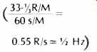
This frequency is low enough to be innocuous.
A previously unrecognized minor source of arm excitation is the change of stylus drag force with modulation.
Signals which have a substantial angle at the axis crossing; i.e., a high recorded velocity, will increase the drag force considerably, and the arm offset angle or the vertical tracking angle geometry will cause a component of the drag force to move the pickup.
This can be seen in Figs. 5 and 6. If the drag force varies, the pickup will move, and the "scrubbing motion" occurs.
It should be clear at this point that an under-damped cartridge tonearm resonance can create a serious problem when that resonance is excited.
Obviously many potential sources of excitation exist, the most predominant being record warp. Thus, reducing the effect of resonance should be the primary objective in improving playback under practical conditions.
Static Electricity on Phonograph Records: To the audiophile who deals with high performance record playing equipment, static electricity charges are a perverse and irregular nuisance, usually producing annoyance, but occasionally causing calamities. The problems are usually worse in winter, when the humidity is low, but some effects can still appear in the middle of summer.
These effects show up in many forms, principally (a) crackling, popping, or frying noises during record playback; (b) brief popping sounds during arm setdown; (c) excess stylus force due to electrostatic attraction of the cartridge to the record being played; (d) in changers, attraction of the arm to the unplayed stack, interfering with setdown and reducing tracking force to induce mistracking, and (e) dust and dirt attracted to the playing surface, producing wear and playback noise.
This is a formidable list, and some of these effects have not been fully recognized previously.
Static electricity was the first form of electrical effect to be noticed many hundreds of years ago, but the nature of the mechanisms producing charges are almost as obscure now as then.
Any form of friction, motion, or contact is likely to produce charges, and vinyl is one of the most easily charged materials available. Hence, such common actions as removing a record from its jacket or wiping it with a cloth or brush, is certain to produce a charge that will be hard to remove. Unlike the "ordinary" electricity which produces useful effects in a closed circuit, static electricity lives in open circuits. If the air is dry and the surface resistance high, a charge may take days or even weeks to disappear. In the meantime, it is just waiting for a chance to cause trouble.
The classical method of measuring charges is the electroscope, a simple instrument in which the mutual repulsion of two gold leaves causes them to stand apart, the angle being related to the voltage which is being measured.
This device endears itself to users for its habit of self-destruction when exposed to strong charges. Fortunately, special instruments have now been developed to measure static charges, since ordinary voltmeters are not suitable.
A few minutes of experimentation with such an instrument will show how tenacious and easily produced the charges are. Even wiping the record with a damp cloth may produce charges rather than neutralizing them.
Incidentally, measurements with these instruments have shown that electrification from the direct friction between the diamond and vinyl is, oddly enough, negligible.
The results shown in Table 1 illustrate several interesting points.
First, it verifies the observation that placing a charged record on a grounded turntable ( Col. B & C) reduces the effect of the charge because the electrostatic field is concentrated between the turntable and the underside of the record, which reduces the original field. Another way to regard the situation is to recognize that the capacitance has increased greatly, and, since the charge is constant, the voltage must decrease in accordance with the equation V =Q= C. Note that this does not eliminate the charge, but only reduces the external field. When the record is removed from the turntable, the original voltage reappears.
The closer the record is to the conductive surface, the lower the external field produced, up to the 90 percent reduction shown in the table.
The results also show that the static charges on records are always negative and that some records are less susceptible to charges than others. The 30,000-volt measurement in air was accompanied by a considerable crackling sound and seems to be a threshold voltage determined by the breakdown voltage of the air.
This investigation was started in winter, and there was no difficulty producing charges using cat fur and friction. As the season advanced and the humidity increased, the charging became much more erratic, and it was necessary to lightly rub a finger on the rotating record to produce a charge.
Eventually, as the nature of necessary comparisons became clear, the charges would not cooperate at all! Consequently, to make repeatable measurements independent of humidity and rubbing techniques, a system was devised which uses continuous electrification via a high voltage d.c. supply to achieve a calibrated, reproducible charge. The arrangement is shown in Fig. 7.
The probe is a steel phono stylus of 0.006 radius supported 1 inch above the surface of the record. As the record rotates under the probe, it receives a charge which builds up to a saturation point. A calibration curve (Fig. 8) gives the relation between the probe voltage and the charge on the record. The measured charges are nicely encompassed by the calibration curve.
As might be expected, it shows a knee which is the breakdown voltage of the charging point. Above the knee, the relationship between probe voltage and record voltage is linear. The only caution to be observed is that the curve can only be used in an increasing direction, i.e., one must start with a neutral record and increase the voltage during experiments.
If the record is fully charged and a lower voltage is then applied, the actual voltage on the record will be somewhere between the former and latter value and, hence, indeterminate.
Discharges to the pickup can be detected by the means shown in Fig. 7, where a sensitive amplified microammeter is connected in the ground return circuit from the pickup. Thus, measurements can be made of both charging and discharging.

Table I--Measurement of Electrostatic Charges on Phonograph Records
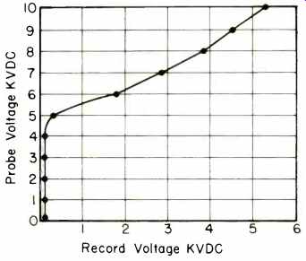
Fig. 8--Voltage Calibration RCA R11624.

Fig. 9--Trackability calibration of the TTR 103 test record, 33 1/3 rpm @ 296
Hz with the V15 Mk III stylus assembly.

Fig. 10--Trackability measurement using electrostatic force on the TTR 103
test record, 33 1/3 rpm @ 296 Hz.

Fig. 11a--No lint on the stylus tip.

Fig. 11b--Lint accumulation around the stylus tip.
Test Results
Typically, no discharge is noted until the charge voltage exceeds a particular value, which we call the threshold voltage, after which the current increases rapidly. Cartridges having a grounded metal shield and grounded stylus shank have threshold voltages in the region of 4000 to 5000 volts. Thus, charges below this voltage will not cause a discharge, but will exert an electrostatic force on the cartridges.
When a record is charged above the threshold ,voltage, a playing will discharge it down to the threshold voltage of the cartridge but not to zero.
The electrostatic attraction force was measured by making a trackability calibration of, a particular cartridge.
This was done by playing the bands of the Shure Test Record TTR103 and noting the corresponding stylus force for marginal tracking (Fig. 9). The arm was then counterbalanced to zero. The record was charged and then played using the electrostatic force as the sole force. Adjusting the charging voltage for the same marginal tracking as before yields the results shown in Fig. 10. The points above 4200 volts (threshold voltage of cartridge) are not significant with a naturally charged record, because the record will discharge to this level. However, 4200 V can add an extra %, gram to the stylus force! This additional force would increase wear and at least change the in tended tracking conditions significantly.
Possibly of most importance is the fact that a natural charge will be nonuniform and cause cyclic wow or frequency modulation with record rotation. The result can be non-repeatable and probably difficult to identify but would have a clearly discernable effect on sound quality.
Experiments with household dust also show that a record voltage of only 1000 or 2000 V is enough to make fine particles adhere to the record and resist brushing or blowing, especially out of the grooves, where ordinary bristles cannot reach.
From this, we conclude that electrostatic charges can create some serious problems in tracking, distortion, noise, and dust accumulation. This most certainly is a phenomenon which at our present level of sophistication in high-fidelity record reproduction cannot be ignored.
Dirt on the Record and Tip
The effects of dust and other contaminants on the playback process have been the source of study for many years. It has not been possible, as yet, to quantify the exact amount of dirt that would be acceptable, or even to completely spell out the process of dirt accumulation. Suffice it to say that records must be kept clean and that the more care one takes in maintaining cleanliness, the fewer problems will result. Proper brushing of the record before it is played, we feel, is essential for top-quality performance.
While it is not the purpose of this paper to discuss methods of cleaning records, it should be noted that there are a large variety of methods, some of which are considerably better than others.
We have found that even the best of the record cleaning methods still leaves some dust and contamination on the record. The length of time one can play the record before a serious problem results is related to the initial cleanliness of the record, the amount of dirt accumulation on the record during the playing time, and on the stylus tip. Accumulation of dust and lint on the record results in the condition as shown in Fig. 11. As the dirt builds up, it finally reaches a condition such as that shown in Fig. 11b at which time proper tracking cannot be achieved.
The length of time required to develop an accumulation which will create the condition of 11b will depend on the length of the stylus tip. Shure, for example, maintains a minimum distance of 0.014 inch from the bottom of the stylus shank to the end of the diamond. A shorter tip could be used, which would slightly reduce tip mass and offer some very minor advantages in trackability; however, our experience indicates that this would be an improper compromise. Even though excellent care is taken of the record, it is felt that some accommodation to the probability of dirt accumulation must be made.
Since some dirt will accumulate on the stylus, the objective is to provide a design which will avoid the necessity of cleaning the tip for as long as possible. The absolute minimum time would be the playing time for one side of a disc. This would not seem to be a reasonable or practical minimum since one should allow for the playing of a stack of records on a changer. A practical objective, therefore, would be to play at least six records; i.e., roughly two hours, assuming that the records have previously been cleaned properly and that a cover is used over the changer during the playing of the records.
Summary
We have discussed several factors that affect the performance of a phonograph pickup. These factors have been divided into two groups: namely, those which must be considered under ideal playing conditions and the conditions that create practical problems of playback. In the first group, we include frequency response, separation, trackability, tracing and tracking distortion, and skating force.
In the second group are the level of modulation, mechanical noise, arm resonance, static electricity, and contamination.
In the next portion of this article, we will describe means whereby the effects of non-ideal playing conditions can be countered and, in some cases, totally eliminated. Concurrently, significant improvements in playing under ideal conditions can also be achieved.
References
1. J.H. Kogen, "Trackability," Audio, Vol. 50, pp. 19-22, 26-27 (Nov., Dec. 1966).
2. J. Kogen, B. Jakobs, and F. Karlov, "Trackability--1973," Audio, Vol. 57, pp. 16-22 (Aug. 1973).
3. J.H. Kogen, "Tracking Ability Specifications for Phonograph Cartridges," J. Audio Eng. Soc., Vol. 16, pp. 186-190 (April 1968).
4. J.A. Pierce and F.V. Hunt, "On Distortion in Sound Reproduction from Phonograph Records," J. Acoust. Soc. Am., Vol.1, pp. 14-28 (July 1938).
5. B.B. Bauer, "Tracking Angle in Phonograph Pickups," Electronics, Vol. 18, pp. 110-115 (March 1945).
6. J.G. Woodward and E.C. Fox, "A Study of Tracking-Angle Errors in Stereodisk Recording," IEEE Trans. on Audio, Vol. 11, pp. 56-62 (March-April, 1963).
7. B.B. Bauer, "Vertical Tracking Improvements in Stereo Recording," Audio, Vol. 47, pp. 19-20, 46, 68-69 (Feb. 1963).
8. P. Wilson, "Needle-Track Alignment," The Gramophone, Vol. 2, pp. 129-132,167-170 (Sept., Oct. 1924).
9. L. Happ and F. Karlov, "Record Warps and System Playback Performance." J. Audio Eng. Soc., Vol. 24, pp. 630-638 (Oct. 1976).
(Source: Audio magazine, May 1978)
Continued: Phonograph Reproduction --1978: part 2 (Jun. 1978)
= = = =