MANUFACTURER'S SPECIFICATIONS
FM Tuner Section
Usable Sensitivity: 1.8 µV (10.3 dBf).
50-dB Quieting Sensitivity: Mono, 3.2 µV (15.3 dBf); Stereo, 40 µV (37.2 dBf).
Image Rejection: 85 dB.
I.F. Rejection: 90 dB.
Spurious Response Rejection: 100 dB.
AM Suppression: 65 dB.
Capture Ratio: 1.0 dB.
Selectivity: 80 dB. S/N: Mono, 77 dB; Stereo, 73 dB.
THD: Mono, 0.08 percent @ 1 kHz; 0.08 percent @ 100 Hz; 0.15 percent @ 6 kHz; Stereo, 0.1 percent @ 1 kHz; 0.15 percent @ 100 Hz; 0.2 percent @ 6 kHz.
Stereo FM Separation: 50 dB @ 1 kHz, 35 dB at 50 Hz, 45dB Ed 10kHz.
Sub-Carrier Suppression: 60 dB.
Frequency Response: 30 Hz to 15 kHz, ±0.5 dB.
Muting Levels 30 µV (34.8 dBf) and 3.0 µV (14.8 dBf).
AM Tuner Section
Sensitivity: (Internal antenna), 300 µV/m.
Selectivity: 30 dB. S/N: 50 dB.
Image Rejection: 40 dB. THD: 0.4 percent.
Amplifier & Preamplifier Section
Power Output: 100 watts min. continuous per channel, 8 ohm loads, 20 Hz to 20 kHz; 120 watts into 4 ohms.
THD: 0.05 percent.
Damping Factor: 40 @ 8 ohms.
Input Sensitivities: Phono 1&2, moving magnet, 2.0 mV; moving coil, phono 1, 50 µV; AUX & tape 1 & 2, 120 mV.
Phono Overload: MM, 230 mV; MC, 5 mV.
Frequency Response: Phono RIAA ±0.2 dB; high level inputs, 10 Hz to 100 kHz, ±2.5 dB.
S/N Ratios: IHF "A" weighting, MM phonos, 95 dB; MC phono, 85 dB; high level inputs, 100 dB.
Residual Noise: Min. vol., 0.045 mV. NDCR for 0.1 percent THD, 8 ohm @ 1 kHz (See text for explanation): 100 mW to 100 W.
Bass Control Range: ±15 dB @ 20 Hz.
Treble Control Range: ±12 dB @ 20 kHz.
Presence Control Range: ±6 dB @ 3 kHz.
Low Filter Cutoff: 15 Hz & 70 Hz (12 d B/octave).
High Filter Cutoff: 8 kHz & 12 kHz (12 dB/octave).
Tone Control Turnover Frequencies: Bass, 125 & 500 Hz; treble, 2.5 & 8 kHz.
General Specifications
Power Requirements: 120 V, 60 Hz, 480 watts.
Dimensions: 21 1/3, in. (54 cm) W x 6 9/16 in. (16.67 cm) H x 16 15/16 in. (43 cm) D.
Weight: 42 lb. 7 oz. (19.25 kg).
Price: $700.00 (mid 1977)
------------------
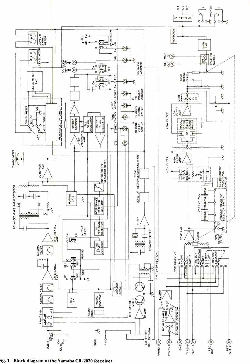
Fig. 1--Block diagram of the Yamaha CR -2020 Receiver.
If you scanned Yamaha's published specifications for their newest top -of -the -line receiver, Model CR -2020, too quickly, you may have missed a new term which they have decided to use for all their new receiver products. It is called NDCR (which stands for "Noise - Distortion Clearance Range"-and it tells us much about the design philosophy of this magnificent receiver and about Yamaha's avowed approach to audio product design. The NCDR spec is intended to convey the maximum and minimum powers (and therefore, the useful dynamic range) of the product for a quoted percentage of noise and distortion. Thus, in addition to quoting the power and distortion at maximum output (and, usually, with the volume control turned all the way up, a condition seldom used in practice), the NDCR number tells you the power range (usually for a more typical volume control setting) that you can achieve for a given figure of noise plus distortion. Furthermore, the value is quoted as measured from the phono input and right on out to the speaker terminals (instead of for the main amp section only, or from preamp to record out, as is often the case with many "spec sheets"). A highly meaningful spec, we think, and one that other manufacturers would do well to emulate.
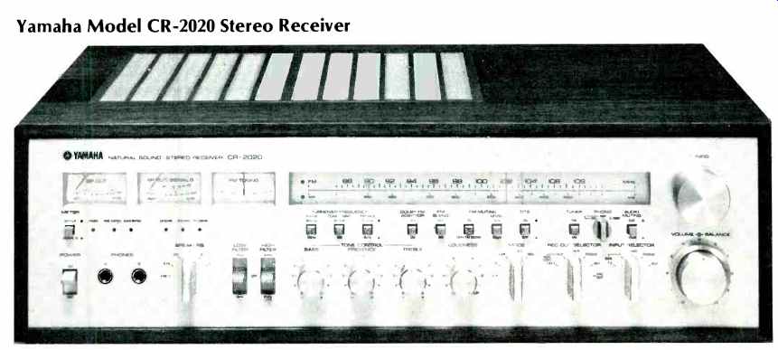
Examining the front panel of the new CR-2020, one cannot help but wonder how Yamaha's engineers were able to cram so many features and controls onto a single component. At the upper left are three meters, set behind uniform cutouts in the panel. The central meter of this trio serves a dual purpose, either combining with its left companion to display power output levels (from around 0.05 watt to 200 watts) on serving as a signal strength and "quality" indicator. When used in the latter mode, the meter needle will fluctuate as well as indicate signal strength when there is multipath interference. The third meter is the usual center-of-channel indicator for FM tuning.
A smoothly gliding "slide-rule" type pointer moves along the well-calibrated linear FM and conventional AM frequency scales, with the scale in use denoted by an illuminated LED at the left and a large flywheel-coupled tuning knob is located at the upper right of the panel. Below the meters are a selector switch which chooses the function of that central meter and six LEDs which give visible indication of power -on, tone control activation, audio muting, FM blend, FM stereo reception, and whether Yamaha's special AFC circuit (which they call OTS, for Optimum Tuning System) is activated. This mild AFC circuit, incidentally, is automatically disabled the moment your fingers touch the tuning knob. Tiny square pushbuttons just below the dial cutout select bass and treble turnover frequencies, defeat the tone circuits altogether, introduce a Dolby adaptor connection circuit (a separate adaptor must be connected at the rear panel for reception of Dolby FM programs), FM blend, FM muting, selection of muting threshold levels (3 or 30 µV), the aforementioned OTS (or AFC) feature, AM/FM selection, and fixed audio muting of 20 dB. A three-position rotary switch located between the last buttons named selects either of the two pairs of phono inputs and determines whether moving magnet or moving coil circuitry will be employed in the Phono 1 circuitry.
The lower bank of controls and features along the panel include a toggle On/Off power switch, two pairs of stereo phone jacks, a speaker selector switch (up to three pairs of speakers can be connected to the CR-2020, but simultaneous listening is restricted to any two pairs), three position low- and high -cut filter switches, bass, presence (midrange) and treble tone controls, rotary loudness control (about which more in a moment), mode switch (with settings for stereo, reverse, L, R, and L+R), a novel six -position "record out" selector (which works completely independently of the program selector and permits tape dubbing as well as recording of all other program sources, regardless of what program source you happen to choose using the adjacent input selector switch), and a dual-concentric volume & balance rotary control pair.
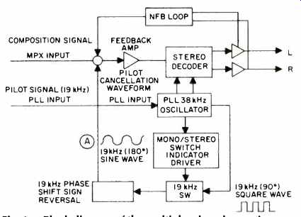
Fig. 1a--Block diagram of the multiplex decoder section.
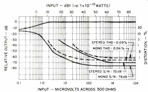
Fig. 2--FM quieting and distortion characteristics.
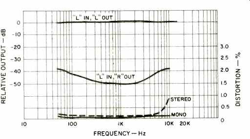
Fig. 3--Separation and distortion vs. frequency.
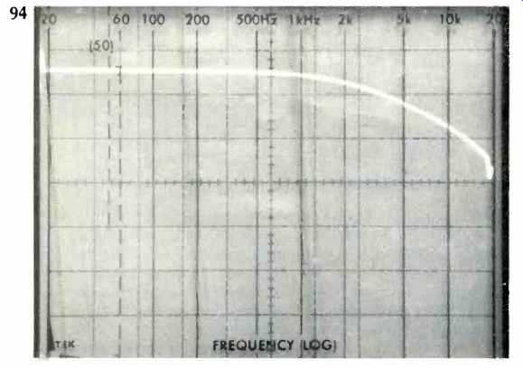
Fig. 4--FM response including the Dolby 75 µs de-emphasis.
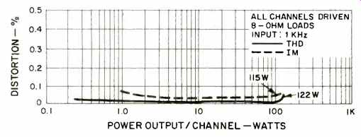
Fig. 5--Harmonic and intermodulation distortion characteristics.
The usual pivotable AM ferrite bar antenna on the rear panel is positioned above a pair of chassis ground terminals and the phono, AUX, tape in, tape out, and Dolby adaptor jacks. Centered on the rear panel are 75-ohm, 300 -ohm, AM, and ground terminals for antenna connections, just below which are preamp-out and main -amp in jacks which are internally switched together or apart by means of a "coupler" switch which comes retained in the "coupled" position to prevent accidental separation of the two sections of the receiver and resulting loss of sound. Three quartets of spring -loaded "piano -key" type speaker terminals, flanked by two unswitched and one switched convenience a.c. receptacle, complete the rear panel layout.
A look within the chassis of the Yamaha CR-2020 discloses a layout which is as well thought out as the front and rear panels. A block diagram of the entire receiver circuit is shown in Fig. 1, and examination of the complete schematic of the unit (which is supplied in the owner's manual) discloses so many new circuit innovations that space does not permit discussion of more than a few of the more important ones.
Of particular interest to us was the unusual FM multiplex decoder circuit, a block diagram of which is shown in Fig. 1a. The input enters the 38 kHz sub-carrier generator in the phase-lock-loop IC, passed through the circuit which generates a 10 kHz square wave and then feeds sine-wave cancellation of the 10 kHz pilot signal into a negative feedback amplifier located before the demodulator. This system obviates the need for low-pass filters which restrict FM frequency response in attempting to reduce sub -carrier output. Yamaha claims an FM frequency response which extends to 18 kHz.
Also of interest to us was Yamaha's use of dual volume control sections for each channel, one section inserted before the tone control amplifier, the other following the filter amplifier. This arrangement provides improved signal-to-noise ratios at all volume settings and, when volume control settings are at minimum, noise is effectively reduced to that of the power amplifier section only.
The Yamaha CR -2020 is the first receiver we have tested which is equipped with a "head amp" or pre -amplifier, making it possible to connect moving-coil phono cartridges directly to the unit without transformers or load requiring step-up other separate "black box" add-ons. The circuit of the equalizer -amplifier features a PNP input, feeding a constant current and single-ended, push-pull output. The output circuit operates in class A at all frequencies up to 20 kHz.
A novel aspect of the tone control circuitry (besides the inclusion of a presence control) is the use of a semiconductor circuit to duplicate the action of inductors in the bass section.
The power amplifier section of the receiver consists of a differential-amplifier first stage with constant-current bias and current mirror circuitry, a constant-current load pre drive section, and Darlington-connected fully complementary single-ended, push-pull direct-coupled driver/output stages, with power consumption-limiter-type transistor protection circuitry. The limiter protection circuitry detects the resistance at the speaker terminals, and if that drops to an abnormally low value (or, if a short circuit occurs), signals reaching the output transistors are limited.
FM Tuner Section Measurements
Mono usable sensitivity measured 1.7 µV (9.8 dBf) in the tuner section of the CR-2020. The 50-dB quieting point in mono required a signal strength of only 2.6 µV (13.5 dBf), while maximum quieting reached a very high 76 dB in the mono mode. Stereo sensitivity was limited by the stereo switching threshold, which was set at 20 µV (31.2 dBf), by which time stereo signals were received with more than 43 dB of quieting, reaching the 50 dB quieting point with an input signal strength of exactly 40 µV (37.2 dBf), as specified.
Distortion as well as quieting characteristics for a 1-kHz test signal in mono and stereo are plotted in Fig. 2. THD in mono and stereo were among the lowest we have recorded for any receiver, let alone higher priced separate tuners. Consistently lower than specified, mono THD measured a mere 0.06 percent, while in stereo, the figure obtained for a 1 kHz signal was a low 0.09 percent.
Stereo FM separation measured 50 dB at mid frequencies, and even at 10 kHz the separation was still a very impressive 38 dB, though not equal to the 45 dB claimed. Separation and distortion versus frequency are shown in Fig. 3. Other specifications confirmed in our lab tests included a 1.0 dB capture ratio, selectivity at 83 dB, AM suppression at exactly 65 dB as claimed, image and i.f. rejection at 90 dB, and sub carrier rejection in excess of the 60 dB claimed. To verify the action of the 19 -kHz "feedback" rejection system and the effectiveness of the filter which follows, we applied a sweep-frequency to the external modulation terminals of our FM generator and plotted the response by means of a spectrum analyzer from 20 Hz to 20 kHz. A 'scope photo of the resultant response is shown in Fig. 4, and the smooth, 6 dB/octave de -emphasis characteristic extends way out to 18 kHz (beyond the required 15 kHz limit) before taking its steep dip at the 19 kHz rejection point.
Though employing only a two-section variable capacitor for the AM section, that circuit does include an untuned r.f. stage as well as a differential mixer and a peak detector circuit. Sensitivity (via the external antenna connection) measured 25 µV, while selectivity was 32 dB, S/N reached the 50 dB claimed, and THD (for 30 percent modulation) measured a very low 0.38 percent.
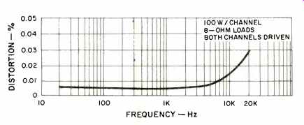
Fig. 6--Distortion vs. frequency (note expanded vertical scale).
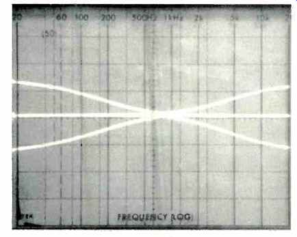
Fig. 7--Bass (500 Hz) and treble (2.5 kHz) turnover range.
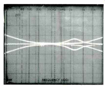
Fig. 8--Bass (125 Hz turnover), treble (8 kHz turnover), and presence control
range.
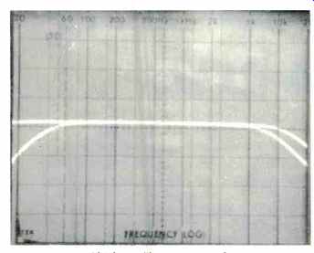
Fig. 9--Low-and high -cut filter response (the 15 Hz sub-sonic filter is
not within the range of this sweep).
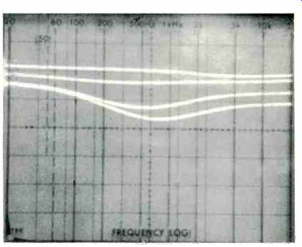
Fig. 10--The variable loudness compensation for the fixed master control
volume setting of the Yamaha CR-2020.
Power Amplifier Section Measurements
The power amplifier section of the Yamaha CR -2020 delivered 122 watts per channel at mid -frequencies into an 8 -ohm load with both channels driven. At 4 ohms, 145 watts per channel was obtained for the rated THD level of 0.05 percent. At the conservatively rated power output level of 100 watts (8 ohms), THD at mid frequencies measured only 0.005 percent and, even at the frequency extremes of 20 Hz and 20 kHz, THD measured only 0.006 percent and 0.03 percent--well below the already extremely low rated THD of 0.05 percent. On the basis of our measurements, the sample unit we tested could have been rated at 113 watts per channel from 20 Hz to 20 kHz with no more than 0.05 percent THD, using 8 -ohm loads. At the 120 watt per channel continuous rating for 4 -ohm loads, THD measured 0.006 percent. IM and THD measurements with respect to power output are plotted in Fig. 5, and while we normally measure "down" to 0.25 watts, the trend of the THD curve is such that we can confirm Yamaha's new NDCR claims down to 0.1 watts. No filters or spectrum analysis were necessary to obtain these readings even at the low levels, where noise normally takes over in many receivers and amplifiers. Thus, the curves shown really represent the sum of noise plus distortion, rather than THD alone.
Distortion versus frequency (for a 100-watt-per-channel output level) is graphed in Fig. 6, and readers are cautioned to observe the expanded scale which had to be used to get a meaningful curve.
Preamplifier Section Measurements
Phono input sensitivities measured exactly 2.0 mV (for the "moving" magnet setting) and 50 microvolts for the moving coil setting which interposes the pre -preamplifier in the circuit. Phono overload was 290 mV for the higher sensitivity reference and 8.0 mV for the moving -coil configuration.
Unweighted signal-to-noise measurements, referred to the above input sensitivities, measured 82 dB and 68 dB respectively. The former reading is actually better than Yamaha's claimed "A" weighted figure. Using a weighting network, we obtained readings of 86 dB for the MM input. Frequency response in phono was accurate with respect to the RIAA curve within 0.1 dB from 30 Hz to 20 kHz, while in high level program inputs it extended from 8 Hz to 100 kHz, ±2.5 dB. Figure 7 illustrates the range of the bass and treble controls when turnover points are set at their positions closest to mid -band, while in Fig. 8 we have plotted the action of these controls when the alternate turnover points are selected. Also superimposed in the 'scope traces of Fig. 8 is the action of Yamaha's presence control, whose center frequency is set somewhat higher than that of other mid -range tone controls which have been appearing recently on better amplifiers and receivers. Our subsequent listening tests revealed that this higher setting actually does deliver more of "presence" effect than does the mid-range control whose center frequency is set closer to the 1-kHz mid-frequency.
The response characteristics of Yamaha's two step low and high-cut filters are shown in the 'scope photo of Fig. 9. Although we activated the 15-Hz filter cut in the upper trace of these two sweeps, the cut action obviously occurred below the low frequency extreme of our sweep -frequency generator (20 Hz) and therefore does not show up on the scope presentation. The 12 -dB per -octave slopes of the other filter positions, as well as the cut-off points chosen by Yamaha, show clearly how much music is retained while filtering out high and low frequency noise and rumble.
Figure 10 shows the action of Yamaha's unique loudness control arrangement and requires a bit of explaining. Yamaha is one of the very few manufacturers of receivers and amplifiers who incorporate a loudness/volume control arrangement that is truly effective and meaningful. Rather than supply a switch, which introduces arbitrary degrees of Fletcher-Munson loudness compensation, regardless of program source levels, speaker efficiencies, etc., Yamaha provides a continuously variable loudness control. Proper setup of this control requires that the listener first set a given program source to naturally loud or life-like levels by means of the regular master volume control. Then, if more moderate listening levels are desired or required, the user simply lowers the setting of the separate rotary "loudness" control and, as this is done, the exact required amount of loudness compensation is introduced. In this way, correct compensation is achieved for any program source, and the setting of the master volume control has no bearing on this compensation amount. In Fig. 10, then, the different curves were plotted for a fixed setting of the master volume control simply by varying the setting of the completely separate loudness control knob. As can be seen, the attenuation range of this separate control is something of the order of 20 dB (each vertical division on the 'scope face of this and other 'scope presentations in this report equals 10 dB of amplitude variation). In our opinion, if you're going to use any loudness control at all, this is the way it should be configured (unless separate input level controls are provided for every single program source, including the built-in AM and FM audio outputs of a receiver).
Listening and Use Tests
Despite the seeming complexity of the Yamaha CR-2020's front panel, familiarization with its features and controls takes only a few minutes. Once one realizes the degree of control at hand, the Yamaha CR-2020 becomes a joy to use and, more importantly, a joy to hear. Residual noise (both in phono and high level) is audibly lower than on just about any receiver we have tested. Like so many readers of Audio Magazine, we have been turning our attention of late to some of the better moving -coil cartridges which are becoming popular once more. Being able to "plug in" such cartridges directly to the receiver (without matching transformers, separate pre-preamps, or worrying about location for least hum pickup and you name it) is a delight, and the signal-to-noise ratio obtained even with such low-level outputs is incredible. There is no longer any need to "accept" higher hum levels in order to enjoy the transparent uncolored output which some of these newer cartridges are able to deliver.
We have always maintained that power output is only one (and not a terribly important one) of the criteria by which a high quality stereo receiver should be judged. In terms of musical definition and clarity, the Yamaha CR-2020 surpasses many of the higher powered receivers we have recently tested. It offers enough power to even drive some of the more inefficient speaker systems around (remember, 180 watts is a mere 2.55 dB more than 100 watts), is manageable in terms of its size and weight (after, all, that is supposed to be the argument in favor of an all-in-one audio electronic component), and, unless someone can come up with a control or switching feature which Yamaha (or we) haven't thought of, provides all the sophistication asked for by the seasoned audiophile without intimidating the neophyte.
This is one receiver that just should not be judged on a "dollar per watt" basis. However, if that measure is applied, you may well conclude that the Yamaha CR-2020 is underpriced!
--Leonard Feldman
(Source: Audio magazine, June 1977)
Also see:
Yamaha CX-10000 Preamplifier (Jan. 1989)
Yamaha Model B1 Power Amplifier (Aug. 1975)
Yamaha M-70 Power Amplifier (Jan. 1984)
Yamaha Concert System 70 (One-Brand Systems) (Aug. 1982)
= = = =