1. Fosgate Electronics Model PR-7000 "Power Punch" Audio Amplifier
The quest for higher audio power and better fidelity on the road (in cars, vans, trailers, boats and even trucks) has prompted a good many manufacturers to come up with separate audio amplifiers that can be added to any vehicular sound system operating from a standard 12-volt car battery.
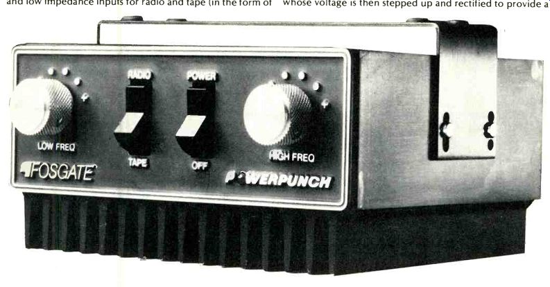
Fosgate Electronics, Inc., of Phoenix, Arizona offers a line of such amplifiers, the more powerful of which is their Model PR-7000 Power Punch, shown here. More than just a two channel power amplifier, the unit provides five degrees of bass boost and five degrees of treble boost in addition to a flat response setting.
The front panel of the PR-7000 contains two rocker switches, one for power on-off switching, the other for selecting radio or tape inputs. Six-position rotary switches to either side of these switches take care of the aforementioned equalization or boost positions.
The rear panel of the PR-7000 is equipped with a slide switch which varies input sensitivity of the amplifier, high and low impedance inputs for radio and tape (in the form of standard phono tip jacks for the high impedance inputs, and screw terminals for the low impedance inputs) and speaker output terminals. The two types of inputs are provided so that a user who does not wish to "tap into" the earlier stages of an existing car radio or tape machine can connect directly from the "speaker" output terminals of those program sources to the low-impedance inputs provided on the PR 7000. Of course, doing so (as Fosgate mentions in their manual) will result in poorer fidelity, since the higher-distortion signals appearing at the output of your present equipment will be fed as an input voltage to the new amplifier.
===========
Fosgate Electronics Model PR-7000 "Power Punch" Audio Amplifier
Maximum Continuous Power Output @ 1 kHz: 20 watts, 8 ohm load; 35 watts, 4 ohm load.
Distortion: 0.3 per cent, 20 Hz to 20 kHz at half-power; 0.75 per cent, 20 Hz to 20 kHz at full power, 8 ohms.
Frequency Response: Within 0.5 dB, 20 Hz to 20 kHz at half-power into 8 ohms.
Load Impedance: 4 to 16 ohms.
S/N Ratio: 65 dB below full output.
Input Sensitivity: High impedance, 0.25 V; low impedance, 3.0 V.
Maximum Equalizer Boost +18 dB @ 55 Hz, +12 dB @ 20 kHz.
Power Requirements: 12 to 14.5 V d.c., negative ground.
Current Drain: 3 amperes "average listening level," 11 amperes, full output, both channels @ 4 ohms.
Input Impedance: Low, 47 ohms; High, 10 kilohms.
Dimensions: 5 3/4 in. (14.6 cm) x 5 (12.7 cm) x 2t4 in. (7.3 cm) H.
Price: $199.95.
J.I.L. Model 615CB/AM/FM/MPX Radio/Stereo Cassette Player
Cassette & Amplifier Section
Power Output: 6 watts rms per channel, 4 ohms, 10 per cent THD.
Frequency Response: 50 Hz to 10 kHz.
Cassette Playback THD: Less than 3.0 per cent.
S/N Ratio: 50 dB.
Separation: Cassette, 35 dB.
Wow & Flutter: Less than 0.35 per cent.
AM/FM/MPX Tuner Section Usable Sensitivity: Less than 10 dB.
Stereo Separation: 25 dB. AFC Holding Range: ±350 kHz.
CB Receiver Section Frequency Range: 29.965 to 27.405 MHz (40 channels).
Sensitivity: 1.0 µV for 10 dB S/N. Selectivity:-6 dB @ 4 kHz.
Adjacent Channel Rejection: 65 dB. Audio Output: 5 watts @ 10 per cent THD. Audio Fidelity: 400 Hz to 2 kHz.
Squelch Sensitivity: 1.0 gV. Spurious Response: 65 dB. CB Transmitter Section Frequency Range: 26.965 to 27.405 MHz (40 Channels). R.F. Output: 4 W maximum.
Modulation Capability: 90 per cent.
Spurious Suppression: 60 dB. Frequency Accuracy: ±0.005 per cent.
General Specifications Current Drain: 3 amperes.
Power Requirements: 11.0 to 16.0 V d.c.
Loudspeaker Impedance: 4 to 8 ohms.
Dimensions: 7 1 in. (19 cm) W x 2 in.
(5 cm) H x 7 in. (17.8 cm) D.
Price: $369.95 Clarion Model PE-666A Cassette/ AM/FM Car Stereo
Radio Section
Maximum Sensitivity: AM, better than 20 dB; FM, better than 12 dB. Selectivity: AM, 20 dB. Image Rejection: AM & FM, more than 40 dB.
I.F. Rejection: AM, 45 dB; FM, 65 d6.
Stereo Separation: More than 20 dB, "Electrical Fidelity": AM,-12 dB @ 4 kHz; FM,-15 dB @ 7 kHz.
Tape Section S/N Ratio: Better than 40 dB. Wow & Flutter: Less than 0.44 per cent.
Crosstalk: Less than 30 dB. Playback Frequency Range: 50 Hz to 10 kHz.
Amplifier Section Maximum Output: 5.0 watts per channel.
"Effective Maximum Output": 3.5 W/channel @ 10 per cent THD.
Load Impedance: 8 ohms x 4.
General Specifications
Dimensions: 7.09 in. (18 cm) W x 1.97 (5 cm) H x 5.51 in. (14 cm) D.
Weight: 3.97 lbs (1.8 kg). Power Requirements: 10.8 to 15.6 V d.c. (14.0 V nominal), less than 1.5 amperes at maximum output (less than 5 amperes during program switching). Price: $229.95.
===========
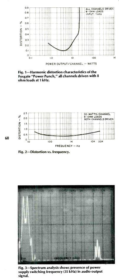
Fig. 1--Harmonic distortion characteristics of the Fosgate "Power Punch," all channels driven with 8 ohm loads at 1 kHz.
Fig. 2--Distortion vs. frequency.
Fig. 3--Spectrum analysis shows presence of power supply switching frequency (35 kHz) in audio output signal.
The entire underside of the Fosgate PR-7000 is one giant heat sink to dissipate the heat produced by the high-level outputs this unit is able to deliver. The mathematically inclined reader, having noted the power output specifications of this product, may be wondering how it is possible to obtain 20 watts of output across an 8-ohm load, using a 12-volt car battery supply. After all, the rms voltage corresponding to that power level equals 12.65 volts which means the peak to-peak voltage must be able to reach a value of approximately 30.4 volts! The answer is that Fosgate uses a d.c.-to-d.c. converter type of power supply which includes a super audible frequency power oscillator (operating at 35 kHz), whose voltage is then stepped up and rectified to provide a dual-polarity 21 volt powering source for the output stages of this compact unit.
Laboratory Measurements
The use of this high-frequency power supply, as well as certain grounding considerations of the PR-7000 (which would pose no problem when used with actual loudspeaker loads, each of which is separately wired) made it impossible for us to use our distortion analyzer in the usual manner.
Fortunately, we were able to measure outputs and distortion by substituting our spectrum analyzer and interpreting distortion components indirectly. As shown in the graph of Fig.
1, at 20 watts output, into 8 ohm loads, the amplifier exhibited a distortion level of 0.4 per cent. The 1.0 per cent THD level was reached with an output of 22.0 watts, both channels driven. At 4 ohms, output was 37 watts for the same 1.0 per cent THD level. All of these measurements were, of course, made with the equalizer switches set to their "0" or flat response positions.
Figure 2 is a plot of distortion versus frequency for 20 watts output into 8 ohm loads. While Fosgate chose not to specify their rated power output in FTC-approved terms (evidently, the FTC power rule does not apply to amplifiers not intended for "home use"), it is obvious from this graph that they might well have done so, for the distortion at any frequency within the audio spectrum did not exceed 0.75 per cent at this 20-watt power output level.
We referred earlier to the influence of the high-frequency power supply on our test measurements. In carefully examining the sine-wave output waveforms monitored by our 'scope, we noted that there was a small amount of 35 kHz switching voltage present in the waveform. Since this high frequency signal is not audible, it in no way affects the quality of sound reproduced using the PR-7000, but its presence did set a bottom "floor" or limit on distortion readings using a conventional meter-type distortion analyzer. To determine the amount of residual 35 kHz present in the output, we altered the sweep mode of our spectrum analyzer so that it sweeps linearly from 0 to 50 kHz. In Fig. 3, the tall spike at the left represents a full-output audio signal, while at the right of the 'scope face we see the switching-frequency content, some 48 dB lower in amplitude (each vertical division on the scope face equals 10 dB and upper frequency notations should be ignored, as they apply to log-sweep mode). For the Fig. 4 'scope photo, we returned to our usual log sweep mode, applying frequencies from 20 Hz to 20 kHz to the input of the PR-7000. Successive sweeps were made using the six available equalization settings (including the "flat response" setting) of the bass and treble switches on the front panel of the PR-7000. Note, that unlike ordinary bass and treble tone controls found on most home hi-fi equipment, the turnover points of these bass and treble equalizer controls are set far away from the mid-range area and are designed to compensate for the roll-off at the frequency extremes encountered with most car speaker systems. The 36 possible combinations of settings permits you to tailor overall response of your car system so that lows, middles, and highs will be heard in their proper perspective at a variety of listening levels.
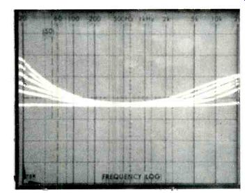
Fig. 4-Composite plot of possible response curves available with the Fosgate PR-7000 auto amplifier.
Summary
The PR-7000 is extremely simple to install under the dashboard and is suspended by means of a single supplied bracket. While it naturally draws a considerable amount of current from your car battery when operated at high levels, under no-signal conditions, current drain was about 1/3 of an ampere. By itself, the unit had a signal-to-noise ratio of 65 dB as claimed, far better than most program sources that would be connected to it. This noise (disregarding the 35 kHz switching component) is primarily of a random nature and, as might be expected from a d.c. operated device, totally free of hum components.
While the orders of distortion produced by the PR-7000 are not nearly as low as those produced by home high fidelity amplifiers, they were far better than those observed on most mini-powered all-in-one car stereo units. If you crave good, big sound in your car or van or boat, this high powered amplifier can deliver it. Fosgate claims that in the close environment of a car, SPL levels of 115 dB have been obtained using the PR-7000. Much, of course, will depend upon the quality of associated speakers used with the amp and with their ability to handle such levels of power. Given a good set of speakers and reasonably good program sources, even with the equalization controls set for full boost (in most cases you won't need that much compensation), midrange average sound levels of 100 dB should be obtainable without taxing the power output capability of the PR7000-and that's really quite a lot of sound when you're on the road.
Leonard Feldman
==============
2. J.I.L. Model 615 CB/AM/FM/MPX. Radio/Stereo Cassette Player
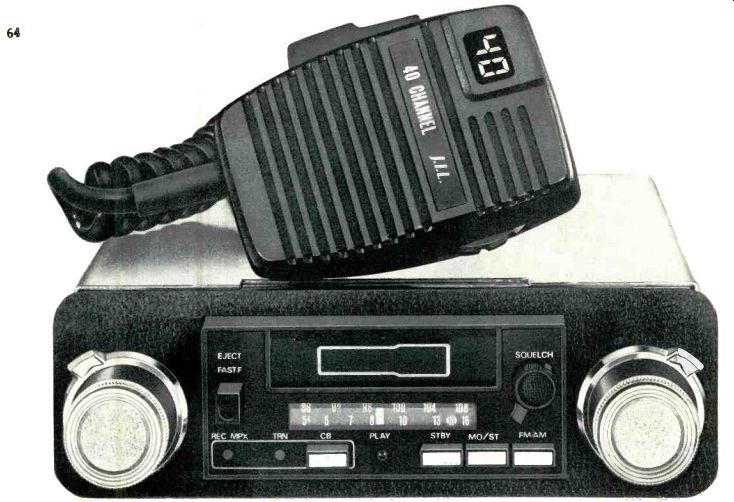
Sooner or later, someone was bound to combine a AM/FM stereo radio-cassette car unit with a 40-channel C transceiver in a single, compact, behind-the-dash unit fo car use, and the distinction of having accomplished that feat belongs to J.I.L. Corporation of America, whose broad line of auto electronic products is probably well known to read ers of this magazine. Even more amazing is the fact that all o these electronic goodies are contained in a cubic volume n greater than that occupied by ordinary AM-FM cassette ca units. Like so many other late-model CB units which including all of the newly approved CB frequencies (now totaling 40 the hand-held microphone serves many important functions other than just being a transducer. A thumbwheel at the right of the microphone assembly changes channel, whose numbers are displayed on the front face of the mike by means of illuminated LED digital readouts. A push-to-talk switch is located on the left of the microphone case, and above it is an r.f. gain control. Needless to say, there's a pretty thick cable running down from this microphone assembly to the chassis proper but that cable terminates in a multi-pin plug so that it can be easily disconnected and stored when not in use, or removed from the car to prevent possible theft. The chassis proper, intended for behind-the-dash permanent mounting, features dual concentric controls at either end of the front panel. The pair of controls at the left turn on the unit and control volume, and serve as a tone control. Those at the right take care of station tuning and left-right speaker balance. A cassette cartridge door flap is centered above the stationary dial scale area and permits insertion of a cassette tape only when it is properly oriented.
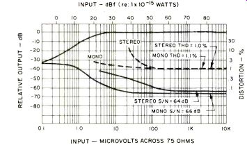
Fig. 1--FM quieting and distortion characteristics of the J.I.L. 615CB.
At the left is a fast-forward tape transport button which also serves as an eject button for the inserted cassette. To the right of the cassette/dial scale area is a continuously variable squelch control used to eliminate noise when no CB channel is being received. Below the dial area, to the right, are the AM/FM selector button, a mono-stereo selector button, and a special standby switch which activates an unusual circuit developed by the people at J.I.L. and patented by them.
With this button depressed, if you are listening to music via any of the available program sources and a CB signal is received on the channel you have selected, the circuit automatically switches over to CB reception, returning to your previous program source once the received signal goes off the air! Additional features at the lower left of the panel's center area are a CB button (depressed for continuous CB operation), a "transmit" light, and a dual-purpose indicator light that illuminates when CB signals are received (so long as squelch is overcome) or, in the case of FM reception, when a stereo FM signal is tuned to. Another indicator light centered below the dial area tells you that you are listening to a tape cassette program. All of this on a panel surface that measures only 2 in. by 7 1/2 in. wide!
Circuit Highlights
A complete schematic diagram is supplied in the owner's manual accompanying the J.I.L. 615CB and, while it does not detail construction of the FM front end of the unit, we did note that the i.f. section uses an IC amplifier, plus a second IC limiter-quadrature detector circuit followed by an IC phase-lock-loop multiplex decoder section. The AM circuitry uses three bi-polar transistor stages in a fairly conventional circuit arrangement. Tape head signal pre amplification is accomplished by means of a single dual channel IC, while the main amplifier module contains a pair of IC power circuits, one for each speaker channel plus two additional voltage amplifier bi-polar transistor stages. The novel tone control arrangement used in this amplifier circuit combines the action of a conventional treble control with that of bass-boost loudness compensation, so that rotation of the control clockwise (when the volume control is at less than maximum settings) results in simultaneous bass boost and treble attenuation. A separate module board is used for the CB transmit circuitry with another p.c. assembly used for the CB-receive section. CB frequencies are determined by the now-popular phase-lock-loop method which requires only a pair of quartz crystals, one cut to a frequency of 9.785 MHz, the other tuned to 10.240 MHz. Total solid state complement of the 615CB includes 10 IC's, 33 transistors and 31 diodes.
FM Section Measurement
Figure 1 details mono and stereo FM quieting and distortion characteristics of the FM tuner section of the 615CB. At strong signal levels, THD in both mono and stereo were virtually identical, at around 1.0 per cent. Mono usable sensitivity measured 2.5µV (15.2 dBf) while in stereo (largely because of increased levels of distortion), usable sensitivity was 40 µV (43.3 dBf). The 50 dB quieting point in mono occurred with an input of 3.0 µV (4.7 dBf) and in stereo the corresponding signal strength measured 50 µV (45.2 dBf). Distortion in mono was governed by the inability of the detector circuit to handle full, 100 per cent modulation in a linear fashion. For our separation and distortion versus frequency measurements we therefore "backed off" the signal generator to 75 per cent modulation and results are plotted in Fig. 2. Note, that with this slight reduction in deviation of the audio modulating signal, mono THD decreased to 0.6 per cent at 1 kHz, a not unreasonable figure in a unit of this type. Frequency response (upper curve of Fig. 2) conformed nicely to the required 75 microsecond de-emphasis curve from around 100 Hz to 8 kHz, but rolled off a bit too quickly beyond those limits. Stereo switching threshold takes place with a signal input of 3.0 µV (20.76 dBf) but considerably stronger signals are needed before stereo listening becomes completely acceptable.
Overall frequency response (including FM de-emphasis)
in FM, at extreme settings of the front panel tone control, are plotted by means of a spectrum analyzer in the 'scope photo of Fig. 3.
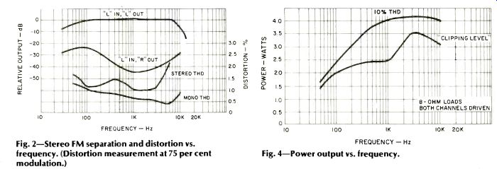
Fig. 2--Stereo FM separation and distortion vs. frequency. (Distortion measurement at 75 per cent modulation.) Fig. 4--Power output vs. frequency.
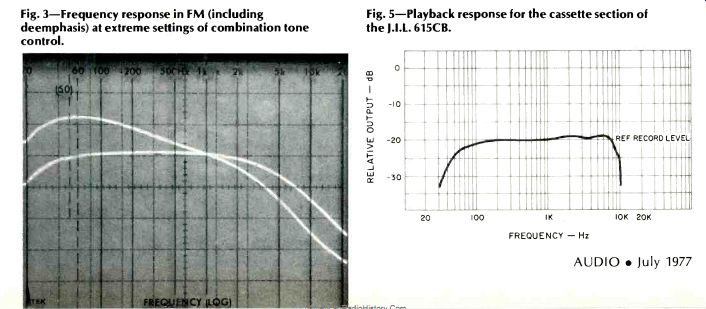
Fig. 3--Frequency response in FM (including de-emphasis) at extreme settings of combination tone control. Fig. 5--Playback response for the cassette section of the J.I.L. 615CB.
Amplifier Measurements
In view of the low power output claimed for the amplifier section of the 615CB, instead of plotting a curve of distortion versus power output, we measured power output capability for 10 per cent THD and for clipping level at a variety of audio frequencies and plotted results in Fig. 4. At mid-frequencies, the unit delivered 4.0 watts per channel, both channels driven, into 8 ohm loads before the 10 per cent THD level was reached. Evidence of clipping was seen at considerably lower power levels, as plotted in the lower curve of Fig. 4.
Cassette Section Measurements
Using our test tape prepared on a reference Nakamichi 1000 cassette deck, at-20 dB recording level, we plotted playback response of the cassette section of the 615CB. Results are shown in Fig. 5, and response was off by 3 dB at 60 Hz and 9 kHz. Wow-and-flutter measured an acceptable 0.18 percent W rms. If J.I.L. had had a bit more room in this compact model, a fast-reverse tape transport mode would have been a welcome addition to the features incorporated for the cassette playback section of the product.
CB Tests
Since our laboratory is not equipped to perform definitive measurements on CB equipment (and such tests are available in publications devoted to CB equipment), all we could do regarding the CB section was put it through its paces and listen to signals picked up on the various channels. There were plenty of these, even with only a rudimentary whip antenna hooked up to the CB-antenna connector, including music re-broadcast from a radio (illegal), a fair amount of profanity (illegal) and even one or two serious conversations which were obviously intended primarily for communication between citizens in our immediate area (legal). Since we are totally against illegal use of CB, our attempts to transmit were limited to a quick call, using our self-assigned call letters (KLF-11023) as instructed on the "temporary license form" provided with the unit. After establishing contact with a youngster down the block, we were satisfied that the CB portion of the 615CB was, indeed, operative in both modes. Fearful of possible wrath from the FCC, that concluded our base-station operation for the evening.
Summary
J.I.L.'s 615CB offers a great deal of entertainment-on wheels for its not unreasonable price. Since its FM tuner section is a cut above the average units found in "car radios" and its cassette deck section is certainly no poorer than those offered by most of the competition, the incorporation of CB in this all-around unit makes it an extremely attractive package for those who want to communicate while driving and still want to enjoy a bit of music without having to usurp all available under-the-dash leg room by the addition of separate add-on boxes.
Leonard Feldman
=================
3. Clarion Model PE-666A Cassette/AM/FM Car Stereo
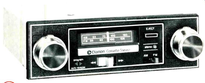
Here is another of those multi-function, add-on, behind the dash-board, AM-FM cassette units, this one by Clarion.
The published specifications shown above are reproduced here exactly as shown on that company's single-sheet "owner's guide," and if you don't understand all of them, well, you're not alone. We will, however, check the unit out in accordance with our accepted procedures, so you can judge against our usual "standards." The front panel of Clarion's PE-666A features dual concentric knobs at each end, one pair for volume/power and tone control, the other for station tuning and speaker fading (front to rear pair) A push of the volume control reverses tape direction, and the unit also features automatic reversal of cassettes at end of play (as indicated by a pair of illuminated arrows near the volume control). A fast forward/rewind lever is located below the dial area, but its lever must be manually held to engage the fast transport modes. The dial area and pointer swing away to permit insertion of the cassette which then drops into correct positioning, and can only be ejected by means of an eject button located at the upper right, near the dial area. A stereo indicator light and an FM/AM band switch complete the front panel layout.
The connection diagram of Fig. 1 illustrates how front and rear stereo speaker pairs may be wired to the PE-666A, and necessary leads and hardware are supplied with the unit.
Circuit Features
The FM front end of the PE-666A is inductance tuned and utilizes bi-polar r.f., mixer and oscillator stages. Four bipolar transistors are used in the FM i.f. section, followed by an IC multiplex decoder. The AM tuner section utilizes a total of four transistors and is also inductively tuned. ICs are used to amplify low-level tape signals as well as for the power amplifier sections of the unit, which connect, via the fader control, to the pairs of speaker terminals. A power board containing four transistors is used to drive the d.c. tape transport motor. A separate illumination lead can be connected to the car's dash illumination system so that the PE-666Á's dial can be dimmed with the rest of the dash illumination. Powering a motorized car antenna is also made possible by connecting it to yet another lead emanating from the PE-666A.
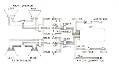
Fig. 1--Speaker wiring diagram for the Clarion-666A car stereo unit.
(Source: Audio magazine.)
Also see:
= = = =