by M.J. Salvati
Often an audiophile buys a quality speaker system together with a quality receiver or amplifier and runs into trouble. He finds that the sound cuts in and out or stops entirely, even at moderate sound levels, due to the operation of the amplifier's protective circuitry. When asked, the speaker manufacturer claims the amplifier is defective and the amplifier manufacturer claims the speakers are defective.
In truth, both components may be performing up to spec, but the cause of the trouble is that the two are incompatible. A number of modern amplifiers have elaborate protection circuitry which mutes the amplifier if the load impedance drops below two or three ohms. Unfortunately, speaker impedance ratings are merely nominal values, and the actual impedances vary greatly with frequency. At some frequencies, impedances drop far below the nominal rating. The result is that speakers nominally rated at four ohms will cause such an amplifier to mute when the program material has significant power at a frequency where the speaker impedance dips, even though the total sound power is at a moderate level.
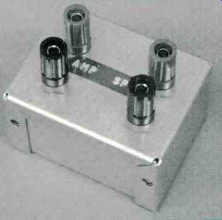
The simple device shown allows you to quickly check a speaker's impedance vs. frequency characteristics, using just your power amplifier, an audio oscillator, and an a.c. voltmeter.
Figure 1 shows how. The device is just a box fitted with connectors and containing a 150-ohm, 4-watt resistor. This high-value resistor converts your transistor power amplifier into an a.c. constant-current source. The a.c. voltage appearing across the speaker terminal is therefore proportional to speaker impedance. By setting the oscillator and amplifier level controls for 15.8 V a.c. output from the power amplifier, the resulting output current results in speaker voltage at the rate of 0.1 volt per ohm. This relationship is most accurate when the speaker impedance is around 8 ohms, and it is accurate enough (±5 percent error) over an impedance range of 0-16 ohms for this check.
Construction
The 150-ohm resistor must be non inductive and rated at least 3 watts.
This rules out readily available wirewound power resistors and any single carbon-composition resistor.
Instead, buy two 300-ohm, 2-watt, 5 percent tolerance carbon-composition resistors. These are more readily available than the more exotic types suitable for this application. If even these are hard to find, you can purchase five 750-ohm, 1-watt or ten 1500-ohm, 'watt resistors, also of 5 percent tolerance. Either way, connect the resistors in parallel to produce a 150-ohm, 5 percent tolerance non-inductive resistor rated at least 4 watts.
If you are the "informal" type, the test setup of Fig. 1 can be assembled with clip leads. If you like things "neat," mount the resistor in a box fitted with 5-way binding posts, as I did.
Use
Oscillators most suitable for this procedure have a constant sinewave output-level vs. frequency characteristic and continuously variable frequency control. A lab-grade sinewave oscillator, like the Krohn-Hite 4200 or any decent function generator, is ideal.
However, a service-grade audio oscillator equipped with an output voltmeter, such as the Heath SG-5218 or Eico 378, will also work well at the cost of some speed and convenience.
The audio amplifier's power rating must be at least 30 watts rms into an 8-ohm load. For maximum convenience, the amplifier must be capable of being set for a flat frequency response from 200 Hz-20 kHz. This is possible with quality amplifiers by simply setting the tone controls to "neutral" or "off" and setting the loudness and high-and low-filter switches to "off." To measure speaker impedance, proceed as follows:
1. Connect the checker between the amplifier and the speaker being checked.
2. Connect an a.c. voltmeter across the AMPL terminals, and adjust the oscillator and amplifier level controls for 15.8 V a.c. at 200 Hz.
3. Transfer the a.c. voltmeter to the SPKR terminals. Record the voltage measured here.
4. Slowly vary the oscillator frequency in suitable increments from 200 Hz to 20 kHz, recording the voltmeter reading (at the SPKR terminals) at each frequency. If your oscillator and power amplifier are not perfectly flat, you must check and reset the input voltage at each frequency.
5. Plot the results of your impedance vs. frequency measurements on semilog graph paper, as I did in Fig. 2. Wherever you find a dip in the curve, make additional measurements at frequencies in that range to pinpoint the frequency of lowest impedance and severity of the dip.
Analyzing The Results
The effect of a big dip below the nominal impedance value depends on several things: Speaker efficiency, the power output characteristics of your power amplifier, and the amplifier's method of connecting multiple speakers. If you have high-efficiency speakers or like soft music, you are unlikely to run into trouble. If the speakers involved are low efficiency and you really try to "use" all those watts you paid for, you should pay particular attention to the following general precautions regarding amplifier/speaker combinations. Note, however, that modern equipment is so diverse that many exceptions do exist.
1. If the amplifier has an 8-ohm power rating, but no 4-ohm rating, it usually means its 4-ohm power capability is less than the 8-ohm rating.
This means that 4-ohm speakers should not be used, not even a single pair. Parallel simultaneous (A & B) operation of two pairs of 8-ohm speakers (main and remote) is similarly not recommended; doing this with 4-ohm speakers is out of the question. However, simultaneous operation of two identical pairs of 4or 8-ohm speakers is perfectly OK if the amplifier uses a series connection to do this.
2. If the amplifier has a respectable 4-ohm power rating, simultaneous parallel operation of two pairs of 4 ohm speakers might be a problem. If the impedance curves dip greatly (3 ohms or so) at some frequencies, this means the amplifier is burdened with a 1 1/2-ohm load impedance at those frequencies! As above, simultaneous operation of series-connected 4-ohm speakers is fine.
3. If two (or more) sets of 4-ohm speakers are to be simultaneously driven, use an amplifier specifically designed for driving very low impedance loads. These are usually separate component power amplifiers whose output stage consists of banks of parallel connected output transistors.
4. An amplifier having electronic overcurrent sensing and/or load impedance sensing is generally less suitable for driving low-impedance loads than is a similarly rated amplifier without this type of protection circuitry.
The exceptions are sophisticated circuits, like the one in the Crown M600, which allow higher current levels for low-impedance loads.
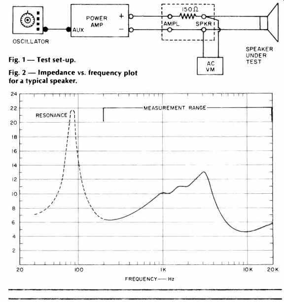
Fig. 1 Test set-up. Fig. 2 Impedance vs. frequency plot for a typical speaker.
( Audio magazine, Aug. 1979)
Also see:
Influence of Listening Rooms On Loudspeaker Systems by Roy F. Allison (Aug. 1979)
The Importance of Speaker Directivity (Sept 1979)
Tape-to-Deck MATCHING For Best Dolby Tracking (Sept. 1979)
= = = =